Fiberon SEC15 M W 6KD 35.5MB Installation guide

Type
Installation guide
INSTALLATION INSTRUCTIONS
berondecking.com
800.573.8841
Manufactured by
Note: Rail lengths will vary slightly due to manufacturing processes. Make sure rails are cut
properly to correct length, and with hole pattern centered between posts before securing.
Fiberon
®
Horizon
®
Railing 6 and 8 ft. Installation Instructions
Required Tools and Supplies:
Top Rail Prole
Bottom Rail Prole
Power Drill
1/8 in. Drill Bit
#2 Square Head Bit
Protective Eye Wear
Tape Measure
Level
Screw Driver, Phillips #2
Speed Square
Miter Saw
Pencil
Adjustable Square
Post Sleeve
Cap
Top Rail Bracket
Top Rail
Bottom Rail
Square
Balusters
Bottom Rail Bracket
YES
2-1/8 in. minimum from rail end to baluster
NO
Post Sleeve
Post Sleeve
Base Moulding
Prior to installing railing: Please consult local zoning laws in regard to load requirements and bottom space requirements for rails. All
supporting structures must be in accordance with applicable building codes. Neighborhood associations and/or historic districts may regulate
size, placement and type of railing. Apply for permits if required by local authorities and codes. Ensure compliance prior to installation. Local
building code requirements will always supersede any and all suggested procedures and measurements in the following installation. The
following installation instructions are intended as a general guideline based on common building practices used in railing installation.
When top and bottom rail length is greater than the distance between posts, trim both top and bottom rail ends to maintain uniform baluster
spacing. Slide post sleeve base moulding over each post prior to installing bottom rails and press securely into place.
Rail Installation: Trim both ends of rail to maintain uniform baluster spacing. It is critical to ensure the trim mark does not create an open
baluster insert hole at the end of the rail where the bracket is attached. Adjust trim lines to maintain uniform baluster spacing.
Adjustable Crush Block
Railing component list for each section:
Maximum length between post sleeves is 72 inches for a 6 ft. rail or 96 in. for an 8 ft. rail.
1
The most recent installation instructions can be found on our website. Please visit berondecking.com or call Consumer and Technical Support at 800-573-8841.
Fiberon
®
Horizon
®
Railing 6 and 8 ft. Installation Instructions
Cover 4x4 posts or Fiberon surface mount
bracket with post sleeve and verify spacing.
posts should be plumb in both directions.
Place post sleeve base moulding over post
sleeve and slide it down to the deck surface.
Continued on next page
Note: Make sure posts are plumb and
level prior to installing the railing.
Pre-drill holes using a 5/32 in. bit (bracket and
rail shown for clarity).
Note: Using an extended drill bit is
recommended to prevent damage to the rail,
and allow a more perpendicular driving angle.
Note: When using surface mount brackets,
use titanium or cobalt bits only. Pre-drill the
post sleeve and steel bracket with a 1/4 in. bit
until the steel is penetrated. This will allow the
bracket screws to engage the wood 4x4 and
pull the rail snuggly to the post. Do not over
tighten.
Pre-drill holes using a 5/32 in. bit (bracket
shown for clarity).
Secure the bracket with supplied 1 in.
screws. Do not over tighten.
Support the bottom rail level and at the desired
height using the adjustable crush block. Using
a level, center the rail on the posts, then mark
the bracket hole locations.
Flip the bottom rail so that the pre-routed
holes are facing downward. Center the
bracket at each end of the bottom rail. To
help ensure a snug installation, allow 1/32 in.
to 1/16 in. clearance between the bracket
“wing” and end of rail. Mark hole locations.
8
9
Measure the distance between posts.
Center the bottom rail hole pattern within
this dimension and cut to length. Place
between posts checking for snug t. Align
top and bottom rail holes and mark the cut
length on the top rail.
2
1
3
To assemble the adjustable crush block,
push the center up through the base, making
sure that the compression wings align with
the ridges inside the core. Insert until the rst
“click” is heard. If the center is inserted too
far, it can be pushed through completely.
Remove the rail from between the posts.
Find the center point (or 1/3 and 2/3 point
if 2 adjustable crush blocks are provided)
on the bottom underside of the bottom rail.
Pre-drill a hole with a 5/32 in. bit. Secure the
adjustable crush block with the supplied
3/4 in. screws. Do not over tighten.
7
4
5
6
2
The most recent installation instructions can be found on our website. Please visit berondecking.com or call Consumer and Technical Support at 800-573-8841.
Extend the adjustable crush block to the
nal height making sure the rail is level.
Lock the block in place by drilling a 5/32 in.
hole into one face, and securing with the
supplied 3/4 in. screws. Do not over tighten.
Cover the exposed head of the screw with
the supplied screw cap.
17
18
12
11
Flip the top rail so that the pre-routed holes
are facing upward. Center the bracket on
the rail. To ensure a snug installation, allow
1/32 in. to 1/16 in. clearance between the
bracket “wing” and the end of rail. Mark hole
locations.
13
Place two balusters onto the bottom rail, one
baluster on each end.
Lower the top rail onto the two balusters,
making sure to line up the baluster inserts
with the top rail routed holes, until top rail is
fully seated on balusters.
Pre-drill holes using a 5/32 in. bit (bracket
shown for clarity).
Secure the bracket with supplied 1 in.
screws. Do not over tighten.
Trim balusters to desired length and press
the top baluster inserts into one end of all
balusters and bottom baluster inserts into the
other end of all balusters.
Note: Top baluster inserts have collars and
bottom baluster inserts do not.
Ensure the top rail is level and mark the top rail
bracket hole locations.
Remove top rail and balusters. Pre-drill holes
using a 5/32 in. bit (bracket shown for clarity).
19
20
14
15
16
Secure the bottom bracket and rail to the
post using the supplied 2 in. screws. Do not
over tighten.
Tip: The use of a long bit extension, or a
exible extension, will help with accessing
the screw heads.
10
Fiberon
®
Horizon
®
Railing 6 and 8 ft. Installation Instructions
3
The most recent installation instructions can be found on our website. Please visit berondecking.com or call Consumer and Technical Support at 800-573-8841.
45
40
35
30
25
20
45
40
35
30
25
20
ANGLE RAIL CUTTING TEMPLATE
Secure the top bracket and rail to the post
using the supplied 2 in. screws. Do not over
tighten.
Complete the assembly by positioning and
gluing post sleeve caps in place.
Fiberon
®
Horizon
®
Rail Angle Bracket
Installation and Cutting Template:
Working from one side to the other, slowly
lower top rail in place aligning baluster inserts
with the top rail routed holes. Fully engage all
baluster inserts into balusters and rails.
23
24
22
Fit all balusters onto the bottom rail.
Note: Balusters can be inserted straight or
sideways to allow for a diamond pattern.
21
(Angle bracket Kit Available by Special Order)
Rails up to 20˚ may be mounted to the post face by using the In Line “L” bracket. Cut
rails at the appropriate angle to t tight against post. Cutting rails greater than 20˚ will
result in a rail that does not fully t on the post. Angles greater than 20˚ require the
use of the angle bracket.
Note: The Minimum distance from post corner to the rst baluster hole is 2-1/4 in.
1. Determine the angle of your installation by using the supplied template.
2. Cut the template out along the appropriate marked lines. (You may want to
photocopy the template as a backup prior to cutting).
3. Position the template on the non-routed at side of the top rail. Mark the proper
cutting angle.
4. Position the template on the non-routed, underside surface of the bottom rail.
Mark the proper cutting angle. Template will be reversed from top rail.
5. Ensure baluster holes are equidistant from the end of rail to ensure proper vertical
alignment.
6. Make angle cuts in top and bottom rails.
7. Align the angle brackets with the cut in the railing. Inset the bracket 1/16 in. (2
mm) from rails end. Mark the three screw hole locations on both rails. Repeat at
opposite end. Pre-drill 5/32 in. (3 mm) holes at desired locations.
8. After tting angles to posts, follow the line rail instructions (Steps 5 through 23) to
complete the rail section installation.
4
The most recent installation instructions can be found on our website. Please visit berondecking.com or call Consumer and Technical Support at 800-573-8841.
The 6 ft. rail length measures
66-1/4 in. from post to post
Maximum distance between post sleeves is
56-3/16 inches for a 6 ft. rail
Building codes are very specic on allowable
angles and widths. It is very important to
consult with your local building code ofcials
and plan your stair layout accordingly.
Ensure that you leave adequate space for
graspable hand rail if applicable. “Dry tting”
intermediate post placement will result in
easier and better looking installations, and
may avoid placement of post mounting
brackets in areas where screws cannot
attache to the guardrail.
Pre-drill holes with a 5/32 in. drill bit (bracket
shown for clarity).
Secure all brackets with supplied 1 in.
screws. Do not over tighten.
Note: The slope of the stairs can be 27 to
37 degrees.
Center the hole pattern between the posts
allowing a minimum 2-3/4 in. from rail end to
routed baluster insert holes.
Mark the angle on the bottom rail using the
inside of each post. Cut the bottom rail to
required length, and check for a snug t.
Install 4x4 posts in the pre-determined
locations, cover with post sleeve and verify
spacing. Posts should be plumb in both
directions. Place post sleeve base moulding
over post sleeve and slide it down to the
deck surface.
2
1
6
5
4
7
8
Note: Rail lengths will vary slightly due to
manufacturing processes. Make sure rails
are cut properly to correct length.
Place the brackets on the at side of
the bottom rail (no holes), and inside the
channel of the top rail (with holes), making
sure to leave 1/32 in. to 1/16 in. space
from the cut edge of the rail. Using the
bracket as a template, mark the hole
locations.
Transfer the cut angle and cut top rail to
length.
Measure the distance from the cut bottom
rail end to the rst hole. Transfer the
dimension to the top rail, then align both
rails together.
3
Fiberon
®
Horizon
®
Stair Railing 6 ft. Installation Instructions
5
The most recent installation instructions can be found on our website. Please visit berondecking.com or call Consumer and Technical Support at 800-573-8841.
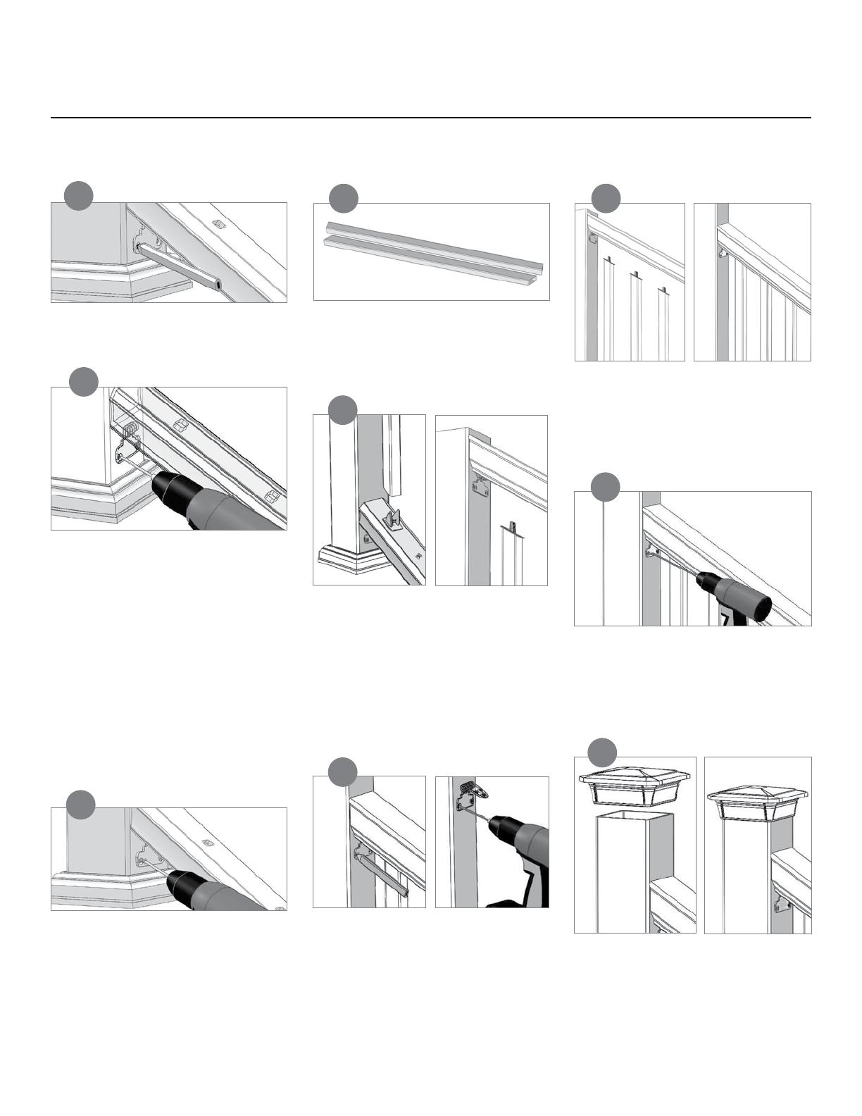
Place the bottom rail between the posts.
Using the bracket as a guide, mark the
location of the holes.
Press the top baluster inserts into the top
end of the balusters and press bottom
baluster inserts into the bottom end of the
balusters. Place two balusters onto the
bottom rail, one baluster on each end. Lower
the top rail onto the two balusters, making
sure to line up the baluster inserts with the
top rail routed holes, until top rail is fully
seated on balusters.
Once fully seated, mark the location of the
bracket holes. Remove the top rail and
pre-drill the holes with a 5/32 in. bit, angling
slightly upward and inward to allow for
clearance from the rail when it is repositioned
for securing (bracket outline shown for clarity).
Secure the top rail to the post at both ends
using the supplied 2 in. screws. Do not over
tighten.
Tip: The use of a long bit extension, or a
exible extension will help access the top
screws.
Mark the stair angle on the ends of each
baluster to be used and cut at an angle
on the top and bottom of each baluster.
Ensure that all of the balusters are of
equal length.
Place all balusters on bottom stair rail.
Working from one side to the other, slowly
lower the top rail in place aligning baluster
inserts with the top rail routed holes. Fully
engage all baluster inserts into balusters
and rails.
Complete the assembly by positioning and
gluing the post sleeve cap in place and a
crush block at the approximate mid-point
of the bottom rail using a quality exterior
adhesive.
Pre-drill the holes with a 5/32 in. bit, angling
slightly upward and inward to allow for
clearance from the rail when it is repositioned
for securing (bracket and rail outline shown for
clarity).
Note: Using an extended drill bit is
recommended to prevent damage to the rail,
and allow a more perpendicular driving angle.
Note: When using surface mount brackets:
use titanium or cobalt bits only. Predrill the
post sleeve and steel bracket with a 1/4 in. bit
until the steel is penetrated. This will allow the
bracket screws to engage the wood 4x4 and
pull the rail snuggly to the post. Do not over
tighten.
Secure the bottom rail to the post at both
ends using the supplied 2 in. screws. Do not
over tighten.
Tip: The use of a long bit extension, or a
exible extension will help with accessing the
screw heads.
9
13
14
16
12
15
11
17
10
Fiberon
®
Horizon
®
Stair Railing 6 ft. Installation Instructions
6
The most recent installation instructions can be found on our website. Please visit berondecking.com or call Consumer and Technical Support at 800-573-8841.
Composite Railing systems are designed to work with a number
of different decking materials and surfaces. Before initiating any
project, obtain a copy of your local building codes and understand
them thoroughly. Local building code requirements will always
supersede any and all suggested procedures and measurements
in the following installation guidelines.
1. Shown is a 5
3
/
4
in. (175 cm) Post Sleeve over a wooden 4 in. x 4
in. (10 cm x 10 cm) using the new wood 4 in. x 4 in. (10 cm x 10
cm) adapters. Begin installation by drilling and securing the lower
4 in. x 4 in. (10 cm x 10 cm) Adapter roughly 1 in.-1
1
/
2
in. (3 cm
- 4 cm) off the deck surface. Make sure to use at least a 1
3
/
4
in.
(53 cm) long athead corrosion-resistant screw (Figure 1).
2. Secure the upper 4x4 Adapter positioned appropriately for the
required nished guardrail height (typically either 36 in. (91 cm)
or 42 in. (107 cm) from deck surface to top of top guardrail).
Placing the top of the 4 in. x 4 in. (10 cm x 10 cm) Adapter at
the desired nal guardrail height should align the center of the
Adapter with the Horizon Rail top bracket (Figure 2).
5. Position the bottom rail against the 5
3
/
4
in. (175 cm) Post with
the bottom bracket pre-assembled. Predrill holes through the
Sleeve, Adapter, and into the wood 4 in. x 4 in. (10 cm x 10
cm) post for the bracket fasteners (Figure 7A).
6. Secure bottom rail with supplied screws (Figure 7B-C).
7. Insert the outermost balusters and baluster daggers at
each end of the bottom rail. Position the top rail with the
preassembled bracket over the balusters and predrill for the
upper bracket fasteners through the Sleeve, Adapter, and into
the wood 4 in. x 4 in. (10 cm x 10 cm) post (Figure 8A).
8. Insert the remaining baluster daggers and balusters and
reposition the top rail. Secure with the supplied top bracket
screws (Figure 8B-C).
1 2
3 4 5
A
B
7
A B C
9 10
A B
8
A B C
C
7
The most recent installation instructions can be found on our website. Please visit berondecking.com or call Consumer and Technical Support at 800-573-8841.
5 3/4 in. (175 cm) Post Sleeve and Angled Rail Installation
3. After cutting to the desired length, slide the 5
3
/
4
in. (175 cm) Post
Sleeve over the wood 4 in. x 4 in. (10 cm x 10 cm) (Figure 3).
4. With the 5
3
/
4
in. (175 cm) Post Sleeve in place, position a 6 in.
(183 cm) Post Skirt followed by the 5-3/4 in. (175 cm) Cap/
Skirt Adapter. Glue the Cap/Skirt adapter in place with an
approved PVC or construction adhesive (Figure 4A). Post, Skirt
and Cap/Skirt Adapter in nal position (Figure 4B).
Note: The 5
3
/
4
in. (175 cm) Post Sleeve allows for a Horizon Rail
to be cut at a 45-degree angle and attached with the standard
brackets (Figure 5).
TIP: use two crush blocks or scrap lumber cut to the required
height to hold the bottom rail at and level.
9. Finish the application by placing a second Cap/Skirt Adapter
over the Post Sleeve (9A-B). Using an approved PVC or
construction adhesive, glue the cap in place and lift the Cap/
Skirt Adapter up to it for nal positioning (Figure 9C-10).
8
FIB-0160-LIT 2/13
9
7 86
Top Channel
Bottom Channel
4
5
3
2
1
Cutting ClearVisionSystem Panels
Note: Leave polyethylene masking in place until after cutting to size (polyethylene masking acts as a lubricant). Sharp saw blade teeth are essential for
achieving good results. Carbide tipped saw blades are recommended for superior cuts. A 10 in. (25 cm) diameter, 80-tooth blade is recommended for all
purpose cutting. (For more detailed cutting information, see www.cyro.com.)
1. Mask off area to be cut using 1in. (3 cm) masking tape.
2. For best results, cut slowly and smoothly.
3. Cut the panel 7in. (18 cm) shorter than the distance between the posts.
Installing ClearVisionSystem (CVS) Panels Inside Horizon Railing
(Code approved for decks no more than 30 in. above grade)
1. Cut top and bottom guardrails to proper length, making sure to center the existing routed hole pattern evenly. Allow 1/32 in.- 1/16
in. (1-2 mm) between vertical at leg of bracket and end of rail to ensure the rail will snug tightly when secured. Use the bracket as a
template and predrill all holes.
2. Secure bracket with three supplied #10 x 1 in. (3 cm) screws.
3. Locate the Crush Block Brackets on the underside of the bottom rail at 1/3 points. Secure using the supplied self-drilling #8 x 1 in. (3
cm) screw. Slide Crush Block over bracket. NOTE: It may be necessary to spread the bracket wider to properly hold the Crush Block.
TIP: Install Post Sleeve Molding at this time. Level bottom rail and pre-drill holes by using the bracket as a template, or mark with pencil.
4. Secure bottom rail to posts using supplied #10 x 2 in. (5 cm) screws.
5. Center aluminum CVS rail on bottom rail across the face and end-to-end. Allow a minimum of 3 in. (8 cm) from end of CVS rail to post,
but not more than 4 in. (10 cm), to allow for air/wind ow-through (Figure 1).
6. Secure aluminum CVS rail using six of the supplied self drilling screws #10 x 1 in. (3 cm) (Figure 2).
7. Allow 1/32 in.-1/16 in. (1-2 mm) from vertical leg of bracket to end of top rail, and predrill hole locations using the bracket as a
template.
8. Secure top bracket to top rail.
9. Center the top aluminum CVS rail, and secure using six of the supplied self drilling screws #10 x 1 in. (3 cm) (Figure 3).
10. Measure 30 in. (76 cm) up from the top of the bottom rail and mark a light line. Align the bottom of the top rail with the line, and pre-drill
the holes.
11. Secure top rail to post using supplied #10 x 2 in. (5 cm) screws.
Top and Bottom Channel (Figure 4)
12. Insert the bottom CVS receiving channel into the bottom aluminum CVS rail. An audible “click” should be heard when properly inserted
(Figure 5).
13. Insert the top CVS receiving channel into the top aluminum CVS rail. An audible “click” should be heard when properly inserted (Figure
6).
14. Install the acrylic panel by starting at one end and fully inserting the panel into the pocket of the top receiving channel. Work towards
the other end inserting the panel fully end-to-end.
15. When properly inserted, the acrylic panel should hover just slightly above the bottom CVS receiving channel.
16. Starting from one end, pull the acrylic panel downward to fully insert into the bottom CVS receiving channel (Figure 7).
17. When properly seated in the bottom rail there should be roughly 3/8 in. (10 mm) space above the top of the acrylic panel (Figure 8).
18. Complete the installation by gluing on the Post Caps (Figure 9).
The most recent installation instructions can be found on our website. Please visit berondecking.com or call Consumer and Technical Support at 800-573-8841.
Clear Vision System Instructions
Figure 4
Fiberon Composite Railing systems are designed to work with a number of
different decking materials and surfaces. Before initiating any project, obtain a
copy of your local building codes and understand them thoroughly. Local building
code requirements will always supersede any and all suggested procedures and
measurements in the following installation guideline.
Kit Includes: (1) Surface Mount Bracket; (1) 4-in x4-in Wood Post;
(4) 1/4-in x 3-in Wedge-Bolt
Anchors; and (4) 5/16-in Fender Washers
For wood composite applications; consumers must purchase:
(4) Galvanized 5/16-in x 5-in Hex bolts; (3-6) #8 x 1-in Flat-head screws and (4)
5/16-in Galvanized Nuts
Note: To ensure proper fastening, it is recommended that the wood thickness be a
minimum of 4-in underneath the mount unless otherwise specied by local building
codes. For more detailed instructions visit us online at www.compositedeck.com.
For Wood Surface Installation:
1. Determine the desired location(s) and finished height of the post sleeve from the
deck surface.
2. The thickness of the wood/composite deck and reinforcement boards underneath
the deck should be a minimum of 4-in. (Two treated and structurally sound 2-in x
8-in lumber under the deck board, Fig 4). Fasten the reinforcement boards with
3-in stainless steel fasteners as shown (Fig 1).
3. Trim the post sleeve to desired length.
4. Trim the length of the 4-in x 4-in wood post insert if required. The wood
post is typically 1-in to 2-in shorter than the post sleeve length.
5. Use the base of the mount as a template and mark the four corner holes on
the deck surface. Mark inside square of bracket on the deck surface.
6. Drill four 3/8-in holes at the marked locations, drilling through the deck board
and the reinforcement boards. Drill a 3/8-in drainage hole in square through
deck board and reinforcement boards for drainage.
7. Locate the mount by aligning the mount corner holes over the drilled holes.
8. Insert the trimmed end of the 4-in x 4-in wood post (included) into the mount. If
necessary, place a shim under the mount to make the post plumb and true (Fig
2). If the wood post is loose within the mounting bracket, secure the wood post
on two opposing sides with at least (3) #8 x 1-in flat-head screws (Not included)
(Fig 3).
9. Insert a 5/16-in x 5-in galvanized hex bolt into the mount holes and the drilled
holes (galvanized bolts & nuts, Not included).
10. Secure the four bolts underneath the reinforcement boards with the 5/16-in
Fender washer (Included In Kit) and 5/16-in galvanized hex nuts (Not included)
(Fig 3).
11. Slide the post sleeve (Not included) over the 4-in x 4-in treated wood post until
it contacts the base of the mount.
Figure 2
4-in x 4-in
Wood Post
3.5-in
3.25-in
3.25-in
8.5-in
3.5-in
Trimmed end is inserted
into the post mount
Figure 1
2-in x 8-in
Reinforcement Boards
3-in Stainless
Steel Fasteners
(Not included)
Figure 3
Post Sleeve
(Not included)
4-in x 4-in
Wood Post
(Included)
Surface Mount Bracket
(Included)
Deck
Board
Inside
Square
5/16-in
Galvanized Nut
(Not included)
#8 x 1-in
at-head screws
(Not included)
5/16-in
Fender Washer
(Included)
VER-0018-LIT 6/14
5-in x 5/16-in
Galvanized Bolts
(Not included)
2-in x 8-in
(5 cm x 20 cm)
9
The most recent installation instructions can be found on our website. Please visit berondecking.com or call Consumer and Technical Support at 800-573-8841.
Post Sleeve SurfaceMount - Wood Surface Installation
10
Fiberon Composite Railing systems are designed to work with a number of
different decking materials and surfaces. Before initiating any project, obtain a
copy of your local building codes and understand them thoroughly. Local building
code requirements will always supersede any and all suggested procedures and
measurements in the following installation guideline.
Kit Includes: (1) Surface Mount Bracket; (1) 4-in x 4-in Wood Post;
(4) 1/4-in x 3-in Wedge-Bolt™ Anchors; and (4) 5/16-in Fender Washers
For concrete composite applications; consumers must purchase:
(3-6) #8 x 1-in Flat-head screws
Note: To ensure proper fastening, it is recommended that the concrete thickness
be a minimum of 4-in unless otherwise specied by local building codes. For more
detailed instructions visit us online at www.compositedeck.com.
For Concrete Surface Installation:
1. Determine the desired location(s) and finished height of the post sleeve from
the deck surface.
2. Trim the post sleeve to the desired length.
3. Trim the length of the 4-in x 4-in wood post insert if required. The wood post length
is typically 1-in to 2-in shorter than the post sleeve length.
4. Use the base of the mount as a template and mark the four corner holes for the
concrete fasteners Wedge-Bolt Anchors (Included in kit).
5. Drill the marked holes per the local building code requirements. Using a 1/4-in
masonry drill bit, drill the holes into the concrete base to a depth of at least 1/2-in
deeper than the length of the 1/4-in x 3-in Wedge-Bolt Anchors. Blow the hole clean
of dust and debris (Fig 3).
6. Locate the mount by aligning the mount corner holes over the drilled holes.
7. Insert the trimmed end of the 4-in x 4-in wood post (included) into the mount. If
necessary, place a shim under the mount to make the post plumb and true. If the
wood post is loose within the mounting bracket, secure the wood post on two
opposing sides with at least (3) #8 x 1-in flat-head screws (Not included).
8. Fasten mount to concrete per local building code requirements (Fig 4). Insert
the four concrete Wedge-Bolt Anchors into the corner holes of the mount. Begin
tightening the Wedge-Bolt Anchor by rotating clock wise and applying pressure in
toward the base. This will engage the first few threads as the Wedge-Bolt Anchor
begins to advance. Continue tightening until the head of the Wedge-Bolt™ Anchor is
firmly seated against the post mount. Repeat for the remaining fasteners.
9. Slide the post sleeve (Not included) over the 4-in x 4-in treated wood post until it
contacts the base of the mount.
Concrete
1/4-in x 3-in
Wedge-Bolt Anchors
(Included)
Figure 3
Post Sleeve Surface
Mount Bracket
(Included)
Figure 4
Figure 2
Figure 1
4x4
Wood Post
3.5-in
3.25-in
3.25-in
8.5-in
3.5-in
Trimmed end is inserted
into the post mount
Post Sleeve
(Not included)
4-in x 4-in
Wood Post
(Included)
#8 x 1-in
at-head screws
(Not included)
VER-0018-LIT 6/14
The most recent installation instructions can be found on our website. Please visit berondecking.com or call Consumer and Technical Support at 800-573-8841.
Post Sleeve Surface Mount - Concrete Surface Installation
Design Grid
FIB-0329-LIT 5/15
berondecking.com
1-800-573-8841
  • Page 1 1
  • Page 2 2
  • Page 3 3
  • Page 4 4
  • Page 5 5
  • Page 6 6
  • Page 7 7
  • Page 8 8
  • Page 9 9
  • Page 10 10
  • Page 11 11
  • Page 12 12

Fiberon SEC15 M W 6KD 35.5MB Installation guide

Type
Installation guide

Ask a question and I''ll find the answer in the document

Finding information in a document is now easier with AI