Page is loading ...

ECOMFORT
PLUS HE -EV
Installation and
servicing instructions
UK
ENSURE THAT THESE INSTRUCTIONS ARE LEFT
FOR THE USER AFTER COMPLETION OF THE
BENCHMARK SECTION
Please read the Important Notice within
this guide regarding your boiler warranty
199838

All descriptions and illustrations provided in this manual have been carefully prepared but we reserve the right to make changes
and improvements in our products that may affect the accuracy of the information contained in this manual.
This boiler may require 2 or more operatives to move it into its installation site, remove it from its packaging and during
movement into its installation location. Manoeuvring the boiler may include the use of a sack truck and involve lifting pushing
and pulling.
Caution should be exercised during these operations.
Operatives should be knowledgeable in handling techniques when performing these tasks and the following precautions
should be considered:
– Grip the boiler at the base
– Be physically capable
– Use personal protective equipment as appropriate e.g. gloves, safety footwear.
During all manoeuvres and handling actions, every attempt should be made to ensure the following unless unavoidable
and/or the weight is light.
– Keep back straight
– Avoid twisting at the waist
– Always grip with the palm of the hand
– Keep load as close to the body as possible
– Always use assistance
WARNING
Caution should be exercised when performing any work on this appliance.
Protective gloves and safety glasses are recommended.
– Avoid direct contact with sharp edges.
– Avoid contact with any hot surfaces.
NOTICE
Please be aware that due to the wet testing of the appliance, there may some residual water in the hydraulic circuit.
– Protect any surfaces, carpets or floorings.
– Use a suitable container to catch any water that escape when removing the protective caps from the connections.
SAFE HANDLING
IMPORTANT NOTICE
For the first year all of our appliances are protected by our manufacturer’s guarantee which covers both parts and
labour.
As you would expect from Sime Ltd, it is our aim to provide our valued customers with the best in after sales and
service.
To take advantage of any extended warranty offered, all you have to do is to adhere to these 3 simple conditions:
• The installation must be carried out to Manufacturers/Benchmark Standards by a Gas Safe Registered
Engineer, and recorded in the installation manual.
• The appliance must be registered with both Sime Ltd and Gas Safe within 30 days of installation.
• The appliance must be serviced annually, by either Sime Ltd or a Gas Safe registered engineer- ensuring that the
Benchmark service record in the installation manual is completed.
Failure to comply with the above will result in only the 12 month warranty being offered.
In the absence of any proof of purchase, the 12 month warranty period will commence from the date of manufacture
of the boiler as shown on the appliance data plate.


The Benchmark Scheme
Sime Ltd is a licensed member of the Benchmark Scheme which aims to improve the standards of installation and
commissioning of domestic heating and hot water systems in the UK and to encourage regular servicing to optimi-
se safety, efficiency and performance.
Benchmark is managed and promoted by the Heating and Hotwater Industry Council.
For more information visit www
.centralheating.co.uk

Please refer to commissioning instructions for filling in the checklist at the back of this installation guide.
Note: All Gas Safe registered installers carry a ID Card.
You can check your installer is Gas Safe Registered by calling 0800 408 5577
CONTENTS
1 DESCRIPTION OF THE BOILER . . . . . . . . . . . . . . . . . . . . . . . . . . . . . . . . . . . . . . . . . . . . . . . . . . . . . . . . . . . . . . . . . . . . . . . . pag. 6
2 INSTALLATION . . . . . . . . . . . . . . . . . . . . . . . . . . . . . . . . . . . . . . . . . . . . . . . . . . . . . . . . . . . . . . . . . . . . . . . . . . . . . . . . . . . . . . . pag. 10
3 CHARACTERISTICS . . . . . . . . . . . . . . . . . . . . . . . . . . . . . . . . . . . . . . . . . . . . . . . . . . . . . . . . . . . . . . . . . . . . . . . . . . . . . . . . . . . pag. 21
4 USE, MAINTENANCE (including BENCHMARK) AND COMMISSIONING . . . . . . . . . . . . . . . . . . . . . . . . . . . . . . . . . . pag. 25
5 FAULT FINDING . . . . . . . . . . . . . . . . . . . . . . . . . . . . . . . . . . . . . . . . . . . . . . . . . . . . . . . . . . . . . . . . . . . . . . . . . . . . . . . . . . . . . . pag. 32
6 REPLACEMENT OF PARTS . . . . . . . . . . . . . . . . . . . . . . . . . . . . . . . . . . . . . . . . . . . . . . . . . . . . . . . . . . . . . . . . . . . . . . . . . . . . pag. 33
7 EXPLODED VIEWS . . . . . . . . . . . . . . . . . . . . . . . . . . . . . . . . . . . . . . . . . . . . . . . . . . . . . . . . . . . . . . . . . . . . . . . . . . . . . . . . . . . pag. 35
SIME COMBINATION BOILERS
Installer checklist
Please remember to carry out the following checks after installation. This will achieve complete customer satis-
faction, and avoid unnecessary service calls. A charge will be made for a service visit where the fault is not due to
a manufacturing defect.
– Has a correct by-pass been fitted and adjusted?
– Has the system and boiler been flushed?
– Is the system and boiler full of water, and the correct pressure showing on the pressure gauge?
– Is the Auto Air Vent open?
– Has the pump been rotated manually?
– Is the gas supply working pressure correct?
– Is the boiler wired correctly? (See installation manual).
– Has the D.H.W. flow rate been set to the customer requirements?
– Has the customer been fully advised on the correct use of the boiler, system and controls?
– Has the Benchmark Checklist in the use and maintenance section of this manual, been completed ?
IPX4D
Important Information
IT IS A STATUTORY REQUIREMENT THAT ALL GAS APPLIANCES ARE INSTALLED BY COMPETENT PERSONS, IN
ACCORDANCE WITH THE GAS SAFETY (INSTALLATION AND USE) REGULATIONS (CURRENT EDITION). The manu-
facturer’s instructions must not be taken as overriding any statutory requirements, and failure to comply with these
regulations may lead to prosecution.
No modifications to the appliance should be made unless they are fully approved by the manufacturer.
GAS LEAKS: DO NOT OPERATE ANY ELECTRICAL SWITCH, OR USE A NAKED FLAME. TURN OFF THE GAS SUPPLY
AND VENTILATE THE AREA BY OPENING DOORS AND WINDOWS CONTACT THE GAS EMERGENCY SERVICE ON
0800111999.
ECOMFORT PLUS 25 HE -EV: Gas Council number 47-283-30
ECOMFORT PLUS 30 HE -EV: Gas Council number 47-283-31
ECOMFORT SYSTEM PLUS 25 HE -EV: Gas Council number 41-283-26
ECOMFORT PLUS 25 HE -EV (without time clock): Gas Council number 47-283-32
ECOMFORT PLUS 30 HE -EV (without time clock): Gas Council number 47-283-33
These appliances comply with the S.E.D.B.U.K. scheme, band “A”

6
450
750
90
245
Ø60/100
111
60
350
166
56
56
23
761
70 70 70 70
=
=
54
160
S3
R
M
G
E
U
FRONT
SIDE
REAR
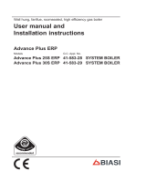
TABLE 2 - Minimum clearances
For servicing
ABOVE THE APPLIANCE CASING 300 mm
AT THE R.H.S. 15 m m
AT THE L.H.S. 15 m m
BELOW THE APPLIANCE CASING 200 mm
IN FRONT OF THE APPLIANCE 500 mm
TABLE 1 - Connections
R C.H. return 22 mm Compression
M C.H. flow 22 mm Compression
G Gas connection 15 mm Compression
E D.H.W. inlet 15 mm Compression
U D.H.W. outlet 15 mm Compression
S3 Condensation outlet ø 20
1.1 INTRODUCTION
ECOMFORT PLUS HE -EV and ECOMFORT
SYSTEM PLUS HE -EV boilers have a con-
densing heat exchanger downstream from
the fan to allow the heat contained in
exhaust fumes to be recovered. The boiler
is equipped as standard with frost protec-
tion and circulating pump antijamming
system.
The instructions given in this manual are
provided to ensure proper installation and
correct operation of the appliance.
All modules are compliant with European
Directives 2009/142/CE,
2004/108/CE, 2006/95/CE and
92/42/CE.
1 DESCRIPTION OF THE BOILER
1.2 DIMENSIONS (Fig. 1)
ECOMFORT PLUS 25-30 HE -EV
450
750
90
245
Ø60/100
5656
23
761
70 7086
54
S3
R
M
G
111
60
350
166
160
Fig. 1
ECOMFORT SYSTEM PLUS 25 HE -EV

7
1.3 TECHNICAL FEATURES (Table 3)
ECOMFORT PLUS 25 HE -EV 30 HE -EV SYSTEM 25 HE -EV
CCooddee bbooiilleerr ((wwiitthh mmeecchhaanniiccaall cclloocckk)) 88110044002222 88110044002211 --
CCooddee bbooiilleerr wwiitthhoouutt ttiimmee cclloocckk 88110044002266 88110044002255 88110044003300
Heat output nominal (80-60°C) kW 25.0 29.0 25,0
Heat output nominal (50-30°C) kW 27.2 31.5 27,2
Heat output minimum (80-60°C) kW 9.6 11.3 9,6
Heat output minimum (50-30°C) kW 10.2 12.0 10,2
Heat input nominal kW 25.5 29.5 25,5
Heat input minimum kW 10.2 12.0 10,2
Efficiency min./nom. output (80-60°C) % 94.2/98.3 94.2/98.3 94,2/98,3
Efficiency min./nom. output (50-30°C) % 100.0/106.8 100.0/106.8 100,0/106,8
Seasonal efficiency rating (SEDBUK) (A) (A) (A)
Termal efficiency (CEE 92/42 directive)
Class NOx 3 3 3
Smokes temperature maximum (80-60°C) °C 60 60 60
Smokes temperature minimum (80-60°C) °C 60 60 60
Smokes temperature maximum (50-30°C) °C 40 40 40
Smokes temperature minimum (50-30°C) °C 40 40 40
Smokes flow kg/h 58.0 61.0 58,0
CO2 maximum/minimum G20 % 7.0/2.5 7.5/2.8 7,0/2,5
CO2 maximum/minimum G30/G31 % 8.0/2.8 8.8/3.3 8,0/2,8
Adsorbed power consumption W 150 160 150
Electrical protection grade IP X4D X4D XD4
CE certification n° 1312BT5040 1312BT5040 1312BT5040
Category II2H3+ II2H3+ II2H3+
Type
B22P-52P/C12-32-42-52-82 B22P-52P/C12-32-42-52-82 B22P-52P/C12-32-42-52-82
WEIGHT kg 40,8 41,2 38,3
CENTRAL HEATING
Maximum water head bar 2,5 2,5 2,5
Maximum temperature °C 85 85 85
Water content boiler l 5.0 5.0 5,0
C.H. setting range °C 40/80 40/80 40/80
Expansion vessel capacity l 8 8 8
Expansion vessel pressure bar 1 1 1
DOMESTIC HOT WATER
Minimum/Maximum pressure bar 0.4/6.0 0.4/6.0 -
D.H.W. flow rate (EN 625) l/min 11.7 13.6 -
Continuous D.H.W. flow rate ∆t 30°C l/min 11.9 13.8 -
Continuous D.H.W. flow rate ∆t 35°C l/min 10.1 11.8 -
D.H.W. setting range °C 10/60 10/60 -
GAS PRESSURE AND NOZZLES
Gas supply pressure G20 mbar 20 20 20
Gas supply pressure G30 mbar 28-30 28-30 28-30
Gas supply pressure G31 mbar 37 37 37
Nozzles quantity n° 12 14 12
Nozzles diameter G20 ø 1.30 1.30 1,30
Nozzles diameter G30/G31 ø 0.77 0.77 0,77
Burner gas pressure min./max. G20 mbar 2.0/11.5 2.1/11.7 2,0/11,5
Burner gas pressure min./max. G30 mbar 4.8/28.5 5.0/28.5 4,8/28,5
Burner gas pressure min./max. G31 mbar 4.8/36.5 5.0/36.5 4,8/28,5
C.H gas consumption G20 m
3
/h 2.70 3.12 2,70
C.H. gas consumption G30/G31 kg/h 2.01 2.33 2,01

8
20
S3
1
2
3
5
4
13
6
15
8
7
10
16
14
11
18
9
23
24
25 26
U
E
G
M
R
12
17
19
21
1.4 FUNCTIONAL DIAGRAM (Fig. 2)
Fig. 2
KKEEYY
1 Post-condenser
2 Smoke stat 100 °C
3 Fan
4 Primary exchanger
5 SM sensor (SM1)
and safety stat (SM2)
6 D.H.W. exchanger
7 Filter
8 Diverter valve
9 Auto air vent
10 Pump
11 DHW flow meter
12 D.H.W. filter
13 Gas valve
14 Pressure relief valve
15 Pressure switch
16 Automatic by-pass
17 Drain vent
18 Expansion vessel
19 Hydrometer
20 Condensate trap
21 Condensate level sensor
23 D.H.W. isolation valve
24 Gas isolation valve
25 C.H. isolation valve
26 C.H. isolation valve
CONNECTIONS
R C.H. return
M C.H. flow
G Gas connection
E D.H.W. inlet
U D.H.W. outlet
S3 Condensation outlet ø 20
20
S3
1
2
3
5
4
13
15
7
10
16
14
18
9
24
25
26
G
M
R
S
17
19
21
ECOMFORT PLUS 25-30 HE -EV
ECOMFORT SYSTEM PLUS 25 HE -EV

9
1
2
3
4
5
6
7
8
9
10
11
12
13
14
15
17
16
Fig. 3
KKEEYY
1 Control panel
2 Primary exchanger
3 SM sensor (SM1 and safety stat SM2)
4Fan
5 Smoke stat 100 °C
6 Air pressure switch
7 Negative test point
8 Positive test point
9 Post-condenser
10 Combustion chamber
11 Ignition/ ionisation electrode
12 Burner
13 Automatic air vent
14 Programming clock (optional)
15 Pump
16 Expansion vessel
17 Condensate trap
1.5 MAIN COMPONENTS (Fig. 3)
NOTE: Analogue pressure gauge see fig. 18/a.

10
The boiler must be installed in a fixed loca-
tion and only by specialized and qualified per-
son in compliance with all instructions con-
tained in this manual. The boiler should be
installed in accordance with the Gas Safety
Regulations.
It is important that the condensate trap
be filled prior to operating the boiler. The
trap can be filled by pouring water care-
fully into the inner flue connection prior to
installation of the flue. Care should be
taken not to allow any water to enter the
outer flue.
2.1 VENTILATION REQUIREMENTS
Detailled recommendations for air supply
are given in BS5440:2. The following notes
are for general guidance:
– It is not necessary to have a purpose pro-
vided air vent in the room or compart-
ment in which the appliance is installed.
2.2 FIXING THE WALL
MOUNTING BRACKET
– Using the template supplied,mark the
position of the two wall mounting brack-
et fixing holes and the flue/air duct hole
on the appropriate wall(s).
– Drill the top two fixing holes using a 10
mm masonry drill and fit the plastic
plugs provided.
– Secure the wall mounting bracket in
position using the screws provided.
Ensure that it is the correct way up, as
indicated in fig. 4.
2.3 CONNECTING UP SYSTEM
Before proceeding to connect up the boiler,
you are recommended to flush out the system
in order to eliminate any foreign bodies that
might be detrimental to the operating efficien-
cy of the appliance. When making the
hydraulic connections, make sure that the
clearances indicated in fig. 1 are respected. To
facilitate the hydraulic connections the boiler
is equipped with a valve pack code 5184817A
complete with instructions sheet.
A safety valve set at 3 bar is fitted to the
appliance, the discharge pipe provided
should be extended to terminate safely
away from the appliance and where a dis-
charge would not cause damage to per-
sons or property but would be detected.
The pipe should be a minimum of 15 mm Ø
and should be able to withstand boiling
water, any should avoid sharp corners or
upward pipe runs where water may be
retained.
Gas Conn
ection: The gas connection must
be made using seamless steel or copper
pipe, galvanized and with threaded joints
provided with gaskets, excluding three-piece
connections, except for initial and end con-
nections. Where the piping has to pass
through walls, a suitable insulating sleeve
must be provided. When sizing gas piping,
from the meter to the boiler, take into
account both the volume flow rates (con-
sumption) in m
3
/h and the relative density
of the gas in question. The sections of the
piping making up the system must be such
as to guarantee a supply of gas sufficient to
cover the maximum demand, limiting pres-
sure loss between the gas meter and any
apparatus being used to not greater than
1.0 mbar for family II gases (natural gas). An
adhesive data badge is sited inside the front
panel; it contains all the technical data iden-
tifying the boiler and the type of gas for
which the boiler is arranged.
Connection of condensation water trap: To
ensure safe disposal of the condensate pro-
duced by the flue gases, reference should be
made to BS6798:2009.
The boiler incorporates a condensate trap
which has a seal of 75mm, therefore no addi-
tional trap is required. It is recommended that
20mm waste pipe is connected to the con-
densate trap with the use of a 20mm solvent
weld socket or elbow.
The condensate should ideally be discharged
internally into an internal waste pipe(washing
machine/sink waste) or a soil pipe to avoid the
risk of freezing.
2.3.1 Dealing with condensate (fig.4/a)
Five suitable drainage points
It is strongly recommend that the conden-
sate drain pipe and its termination are
made internally.
Five suitable drainage points:
1. Internal drain stack pipe
2. Waste water pipe*
3. External drain or gully
*
4. Rainwater hoppers that carry both rain
water and foul water*
5. Purpose-made soakaways
* Care should be taken not to contaminate
any “Grey Water Systems”
Pipework
Condensate pipework should be plastic,
same as used for standard wastewater
plumbing. The advised method of connection
to the condensate trap is by using 20mm
overflow pipe with a socket attached to
cover the condensate trap connection.
Similarly the drainage system where the
condensate discharges to should also be
resistant to the acid condensate.
Pipework should be kept as short as possi-
ble. External runs should be avoided, but
when necessary be a minimum of 3 meter
in 32 mm diameter pipework and lagged
using water resistant material, to avoid
freezing, this also applies to pipe runs in
unheated areas such as garages.
To reduce the possibility of condensate
2 INSTALLATION
Fig. 4
KKEEYY
1 Wall mounting bracket
2 Plastic wall plug (2 Off)
3 Woodscrew (2 Off)
4 Washer (2 Off)
5 Adjustment screw (2 Off)

11
being trapped in the pipe, the number of
bends should be kept to a minimum.
Pipework must be angled down from the
boiler with a fall of at least 2.5°.
The pipework must be supported at a dis-
tance of 0.5 m for inclined runs and 1.0 m
for vertical runs.
Condensate traps
Where the condensate drain is not sealed
to the discharge connection a trap will be
required. The water seal should be 38 mm
or more for external discharge and 75 mm
or more for internal discharge. When con-
necting to a external stack the trap should
be located within the building.
Stack pipes
Condensate connections should be at least
450 mm above any bend at the bottom of a
stack pipe in a single or multi-story dwelling
up to 3 storeys. There are specific require-
ments when connecting to a stack pipe
serving multi-storey buildings greater than
3 storeys.
All connections to stack pipes should avoid
across flow between other Branch pipes.
Soakaways
Any soakaways have to be purpose-made
and located as close to the boiler as possi-
ble, but clear of the buildings foundations
and any buried services. The best option is
to purchase a soakaway from a drainage
manufacturer and install it to the manufac-
turers recommendation.
Condensate disposal positioning and ter-
mination of the condensate drain pipe
The condensate pipe should run and termi-
nate internally to the house soil and vent
stack or waste pipe. Alternatively, the con-
densate can be discharged into the rainwa-
ter system, or into a purpose-made soak
away (condensate absorption point).
An alternative condensate waste pipe
should be considered where the system
could be effected by extreme weather con-
ditions. All connecting drainage pipework
should have a fall of at least 2.5° to the hor-
izontal, or approximately 50 mm per metre
of pipe run.
2.3.2 Requirements for
sealed water systems
The heating system design should be based
on the following information:
a)
The available pump head is given in fig. 12.
b) The burner starts when the C.H. flow
reaches 400÷450 l/h. This safety con-
dition is ensured by the flow switch.
Pipe slope
>2
1
/
2
deg
Internal trap
>75mm
>110mm
(for 100mm stack)
> 450mm
(for up to 3 floors)
100mm Internal stack
Branch
pipe
SINK
Height above
sink >100mm
Internal trap
>75mm
Pipe slope
>2
1
/
2
deg
Height above
sink >100mm
SINK
> 1m
Section of plastic
drain pipe
Holes in side away
from dwelling
Ground level
Alternative
ground level
Limestone
chipping fill
Internal termination of condensate drainage pipe to internal stack
External termination of condensate
drainage pipe via internal discharge
branch (e.g. sink waste) and condensate
syphon
External termination of condensate
drainage pipe via internal discharge
branch (e.g. sink waste - proprietary
fitting) and condensate syphon
External termination of
condensate drainage
pipe to absorpion point
Fig. 4/a

c) The appliance is equipped with an inter-
nal by-pass that operates with system
heads (H) greater than 3 m. The maxi-
mum flow through the by-pass is about
300 l/h. If thermostatic radiator valves
are to be installed, at least one radiator
should be without a thermostatic valve
(usually the bathroom radiator).
d) A sealed system must only be filled by a
competent person using one of the
approved methods shown in fig. 4/b.
The system design should incorporate
the connections appropriate to one of
these methods.
Fitted to the base of the boiler is a ana-
logue pressure gauge, see fig 18/a
page 25.
Ensure that the system is filled to
between 1 and 1.2 bar after all the radi-
ators are vented.
2.4 CHARACTERISTICS
OF FEEDWATER
– All recirculatory systems will be subject
to corrosion unless an appropriate
water treatment is applied. This means
that the efficiency of the system will
deteriorate as corrosion sludge accu-
mulates within the system, risking dam-
age to pump and valves, boiler noise
and circulation problems.
–
For optimum performance after installa-
tion this boiler and its associated central
heating system must be flushed in
accordance with the guidelines given in
BS 7593 “Treatment of water in domes-
tic hot water central heating systems”.
– This must involve the use of a propri-
etary cleanser, Sime Ltd recommend
only the use of Fernox products for the
flushing and final treatment of the sys-
tem water. artificially softened water
must not be used to fill the heating sys-
tem.
Failure to flush and add inhibitor to
the system may invalidate the appli-
ance warranty.
– It is important to check the inhibitor
concentration after installation, system
modification and at every service in
accordance with the manufacturer’s
instructions. (Test kits are available
from inhibitor stockists).
2.5 COAXIAL DUCT ø 60/100
The standard air inlet, smoke outlet assem-
bly is part number 8096250, and is sup-
plied complete with mounting instructions.
NOTE: Ensure that any accessories are
suitable for condensing boilers.
2.5.1 Coaxial flue diaphragm
The boilers "25 HE -EV/SYSTEM 25 HE -
EV" are supplied of series with diaphragm
ø 87.5 to mount like indicated in figure (fig.
4/c).
ATTENTION: the diaphragm should be
used only when the length of the coaxial
duct is below 1,5 m (only for “25 HE -EV”
and “SYSTEM 25 HE -EV” models).
2.5.2 Coaxial duct accessories
The accessories to be used for this type of instal-
lation and some of the connecting systems that
may be adopted are illustrated in
fig. 5.
With the bend included in the kit, the max-
imum length of the flue should not exceed
5.0 meter (25 HE -EV/SYSTEM 25 HE -
EV) - 2.5 meter (30 HE -EV). When the ver-
tical extension code
8086950 is used, the
terminal part of the pipe must always
come out horizontally.
2.6 COAXIAL DUCT
ø 80/125
(only for “30 HE -EV”)
The air inlet-smoke outlet assembly ø
80/125 is supplied in a kit code 8096253
complete with mounting instructions.
With the pipe bend included in the kit, the
maximum length of the piping should not
exceed 5.0 meter.
The diagrams in fig. 5 illustrate a number of
examples of different coaxial outlets ø
80/125.
2.7 KIT ø 60/100 PLUME
CODE 8096260
A special kit code 8096260 is supplied for
this purpose (see fig. 5/a).
2.8 POSITIONING THE
OUTLET TERMINALS
The outlet terminals for forced-draught
appliances may be located in the external
perimeter walls of the building.
To provide some indications of possible solu-
tions, Table 4 gives the minimum distances
to be observed, with reference to the type
of building shown in fig. 6.
12
ONLY FOR “25 HE -EV” AND “SYSTEM 25 HE -EV” MODELS
Fig. 4/c
ALTERNATIVE METHODS OF FILLING A SEALED SYSTEM
Fig. 4/b

13
C12
C32
3
6
1
2
3b
2
1
C12
C32
7
6
4
5
V (vertical) m
7b
5
4
H (horizontal) m
V (vertical) m
H (horizontal) m
60/100 COAXIAL
80/125 COAXIAL
Fig. 5
LIST OF ø 60/100 ACCESSORIES
4 Coaxial duct kit code 8096250
5 Extension L. 1000 code 8096150
5 Extension L. 500 code 8096151
6 Angle flashing plate code 8091300
7 Vertical terminal L. 140 code 8091212
includes item 7b
7b Vertical adapter code 8086950
- 90° degree bend code 8095850
- 45° degree bend code 8095950
LIST OF ø 80/125 ACCESSORIES
1 Coaxial duct kit code 8096253
2 Extension L. 1000 code 8096171
2 Extension L. 500 code 8096170
3 Vertical terminal code 8091212A
includes item 3b
3b Vertical adaptor code 8093150
6 Angled flashing plate code 8091300
- 90° degree bend code 8095870
- 45° degree bend code 8095970
IMPORTANT:
– The insertion of each additional 90° bend with a diameter of 60/100 (code 8095850) reduces the available section by 1.0
meters.
– The insertion of each additional 90° bend with a diameter of 80/125 (code 8095870) reduces the available section by 1,0
meters.
– Each additional 45° curve installed a diameter of 60/100 (code 8095950) reduces the available length by 0,5 metres.
– Each additional 45° curve installed a diameter of 80/125 (code 8095970) reduces the available length by 0,5 metres.
HORIZONTAL FLUES MUST BE LEVEL
NOTE: Before connecting accessories, it is always advisable to lubricate the
internal part of the gaskets with silicon products. Avoid using oils and greases.
Model Length of pipe
ø 60/100 (m) ø 80/125 (m)
HV H V
Min. Max. Min. Max.
25 HE -EV 5,0 6,0 - - - -
30 HE -EV 2,5 3,5 2,5 5,0 4,0 7,0
System 25 HE -EV 5,0 6,0 - - - -
System 30 HE -EV 2,5 3,5 2,5 5,0 4,0 7,0

14
A
ø 60/100
75
ø 60
B
MAXIMUM PERMITTED LENGTHS
KIT ø 60/00 PLUME CODE 8096260
A (Exhaust ø 60/100) B (Flue ø 60)
BOILER MODEL Meters No. of extensions L. 1000 Meters No. of extensions L. 1000
ECOMFORT PLUS 25 HE -EV 0.90 - 3.9 4
ECOMFORT SYSTEM
PLUS 25 HE -EV 1.90 1 2.9 3
0.90 - 2.0 2
ECOMFORT PLUS 30 HE -EV
1.90 1 1.0 1
NOTE: The use of the additional 90° curve (ø 60) sup-
plied as standard reduces the available length (B) by
1 meter.
The use of a 45° curve (ø 60), available on request,
reduces the available length by 0.7 m.
Fig. 5/a

15
– If the terminal discharges into a pathway or passageway check
that combustion products will not cause nuisance and that the
terminal will not obstruct the passageway.
– Where the lowest part of the terminal is fitted less than 2 m
(78 in) above ground, above a balcony or above a flat roof to
which people have access, the terminal MUST be protected by
a purpose designed guard.
– Where the terminal is fitted within 850 mm (34 in) of a plastic
or painted gutter, or 450 mm (18 in) of painted eaves, an alu-
minium shield at least 1,500 mm (59 in) long must be fitted to
the underside of the painted surface.
– The air inlet/outlet flue duct MUST NOT be closer than 10 mm
(0.4 in) to combustible material.
– In certain weather conditions the terminal may emit a plume of
steam. This is normal but positions where this would cause a
nuisance should be avoided.
Terminal position Minimum spacing
A Directly below an openable window, air vent
or any other ventilation opening 300 mm 12 in
B Below guttering, drain pipes or soil pipes (*) 75 mm 3 in
C/D Below eaves, balconies or carport roof 200 mm 8 in
E From vertical drain pipes or soil pipes 75 mm 3 in
F From internal or external corners 300 mm 12 in
G Above adjacent ground, roof or balcony level 300 mm 12 in
H From a boundary or surface facing the boiler 600 mm 24 in
I From a terminal facing the terminal 1,200 mm 48 in
J From an opening in the carport
(eg door, window into dwelling) 1,200 mm 48 in
K Vertically from a terminal on the same wall 1,500 mm 60 in
L Horizontally from a terminal on the same wall 300 mm 12 in
M Horizontally from a vertical terminal to a wall 300 mm 12 in
N Horizontally from an openable window or other opening 300 mm 12 in
P Above an openable window or other opening 300 mm 12 in
Q From an adjacent vertical terminal 600 mm 24 in
(*) For condensing boilers this distance can be reduced to 25 mm without effecting boiler per-
formance, but it will be necessary to protect the surfaces from the effects of condensate
TABLE 4
Fig. 6
2.9 SEPARATE PIPES ø 80
(Optional alternative
twin pipe system)
A special kit may be used to separate the
flue gas outlet from the fresh air intake (fig.
7).
The maximum overall length of the intake
and exhaust ducts depends on the head
losses of the single fittings installed
(excluding the doublers) and must not be
greater than 11.5 mm H
2
O (“25 HE -EV”
and “SYSTEM 25 HE -EV” models) and 8.0
mm H
2
O (“30 HE -EV” model).
See Table 4 for information on the load loss-
es of single accessories and the example of
fig. 7 for information on how to calculate
load losses.
NOTE: Ensure that any accessories are
suitable for condensing boilers.
2.9.1 Separate pipe accessories
Kit code 8089912 is supplied for this pur-
pose (fig. 8).
2.9.2 Separate ducts kit (fig. 8/a)
The diagrams of Figure 8/a show a couple
of examples of the permitted exhausts con-
figurations.

16
KEY
1 Gasket ø 125/95
2 Fixing screw
3 Flue outlet flange
4 Inlet air diaphragm
1
2
3
4
N° segments Total load loss mm H2O
to remove “25 HE -EV/SYSTEM 25 HE -EV”
models
- 0 ÷ 2,0
n° 1 2,0 ÷ 4,0
n° 1 e 2 4,0 ÷ 6,0
da n° 1 a 3 6,0 ÷ 7,0
da n° 1 a 4 7,0 ÷ 8,0
da n° 1 a 6 8,0 ÷ 9,0
da n° 1 a 8 9,0 ÷ 10,0
without diaphragm 10,0 ÷ 11,5
N° segments Total load loss mm H
2O
to remove “30 HE -EV” models
- 0 ÷ 1,0
n° 1 e 2 1,0 ÷ 2,0
da n° 1 a 3 2,0 ÷ 3,0
da n° 1 a 4 3,0 ÷ 4,0
da n° 1 a 6 4,0 ÷ 5,0
da n° 1 a 7 5,0 ÷ 6,0
da n° 1 a 8 6,0 ÷ 7,0
without diaphragm 7,0 ÷ 8,0
Fig. 8
Ø80
Ø80
115
110
245
100
255
165
CS
CA
TABLE 5
Accessories ø 80 Head loss (mm H
2
O) Head loss (mm H
2
O)
“25 HE -EV/SYSTEM 25 HE -EV” “30 HE -EV”
Inlet Outlet Inlet Outlet
90° elbow MF 0.25 0.35 0.30 0.40
45° elbow MF 0.15 0.25 0.20 0.30
Extension L. 1000 (horizontal) 0.20 0.25 0.20 0.30
Extension L. 1000 (vertical) 0.20 0.15 0.20 0.20
Terminal 0.10 0.35 0.10 0.40
Roof outlet terminal * 1.30 0.15 1.50 0.20
* This loss includes the losses of the adaptor 8091401
Fig. 7
KKEEYY
CA Inlet
CS Outlet
Example of allowable installation “25 HE -EV” calculation in that the sum of
the head losses of the single fittings is less than 15.0 mm H
2
O:
Inlet Outlet
9
m horizontal pipe
ø 80 x 0,20 1,80 –
9
m horizontal pipe
ø 80 x 0,25 – 2,25
n° 2
90° elbows
ø 80 x 0,25 0,50 –
n° 2
90° elbows
ø 80 x 0,35 – 0,70
n° 1 terminal ø 80 0.10 0.35
Total head loss
2,40 + 3,30 = 5,7
mm H
2
O

17
2.10 ELECTRICAL CONNECTION
The boiler is supplied with an electric cable.
Should this require replacement, it must be
purchased exclusively from SIME.
The electric power supply to the boiler must
be 230V - 50Hz single-phase through a 3
amp fused main switch, with at least 3 mm
spacing between contacts.
Respect the L and N polarities and the
earth connection.
NOTE: SIME declines all responsibility for
injury or damage to persons, animals or
property, resulting from the failure to pro-
vide for proper earthing of the appliance,
or incorrect connection of external con-
trols. Any fault or component failure due
to incorrect connection of external con-
trols is not covered in the warranty.
2.10.1 Climatic control option
The boiler is designed for connection to an
external temperature sensor, supplied on
request (code 8094101), which can auto-
matically regulate the temperature value of
the boiler output according to the external
temperature.
For installation, follow the instruction in the
package.
2.10.2 Use with different
electronic systems
Some examples are given below of boiler
systems combined with different electronic
systems.
Where necessary, the parameters to be
set in the boiler are given.
For the electrical connections to the boiler
refer to the diagrams (fig. 9 /9a).
Description of the letters indicating the
components shown on the system dia-
grams 1 to 3:
M C.H. flow
R C.H. return
SE External temperature sensor
TA 1-2 Zone room thermostat
VZ 1-2 Zone valve
RL 1-2 Zone relay
Sl Hydraulic separator
P 1-2 Zone pump
IP Floor system
VM Three-way mixer valve
TSB Safety thermostat low
temperature
9
C
C33
11
10
3
1
1
3
3
7
3
12
12
12
Fig. 8/a
C13
3
2
3
1
14
12
13
12
NOTE - HORIZONTAL TERMINALS MUST BE LEVEL
Before connecting accessories, it is always advisable to lubricate the internal
part of the gaskets with silicon products. Avoid using oils and greases.
LIST OF ø 80 ACCESSORIES
1 Separate pipe accessories code 8089912
3 a Extension L. 1000 code 8077351 (6 pz.), 8077351A (single)
3 b Extension L. 500 code 8077350 (6 pz.), 8077350A (single)
7 a Additional 45° MF curve code 8077451(6 pz.), 8077450A(single)
7 b Additional 90° MF curve code 8077450 (6 pz.), 8077451A(single)
9 Manifold, code 8091401
10 Tile for joint code 8091300
11 Terminal for roof exit L. 1381 code 8091212A
13 Union suction/exhaust code 8091401
14 Coaxial exhaust ø 80/125 L. 885 code 8096253A
C32
C12

18
TA
R
M
SE
TA1
TA2
TA
P2
RL
SI
RL1
RL2
P1
P
3 BASIC SYSTEM
MULTI-ZONE SYSTEM WITH PUMP, ROOM THERMOSTATS AND EXTERNAL SENSOR (Code 8094101)
2 BASIC SYSTEM
MULTI-ZONE SYSTEM WITH VALVE, ROOM THERMOSTAT AND EXTERNAL SENSOR (Code 8094101)
TA
R
M
SE
TA
VZ
TA1
VZ1
TA2
VZ2
1 BASIC SYSTEM
SYSTEM WITH SINGLE HEATING ZONE AND ROOM THERMOSTAT, OPTIONAL EXTERNAL SENSOR(Code 8094101)
R
M
SE
TA
CR
EXP

19
2.11 BOILER ELECTRICAL “ECOMFORT PLUS 25-30 HE -EV
TRA
SM1
(3,3 VDC)
BLU-BLUE
BLU-BLUE
VERDE-GREEN
VERDE-GREEN
M
F
CN2
CN1
CN3
12
15
L
N
CN4
CN5
EXP
(24 VDC)
CD.6301440C
CN7
45
49
1
6
7
11
16
29
30
38
CN6
39
44
SM2
(3,3 VDC)
ROSSO - RED
ROSSO - RED
FLM
VERDE - GREEN
ARANCIO- ORANGE
PF
(24 VDC)
NERO-BLACK
NERO-BLACK
1
2
3
VCC
GND
OUT
ROSSO - RED
EAR
PI
230 V
L
N
50 Hz
EV1-2
BLU-BLUE
MARRONE-BROWN
V
MARRONE
BLU-BLUE
MARRONE-BROWN
BLU-BLUE
MARRONE
NERO
BLU
VD
3
1
2
BROWN
TF
(24 VDC)
SL
(24 VDC)
NERO - BLACK
NERO-BLACK
SE
(3,3 VDC)
5
6
4
3
2
1
TA
(24 VDC)
PA
(24 VDC)
ROSSO-RED
ROSSO-RED
NERO-BLACK
BLU-BLUE
BLU-BLUE
VERDE - GREEN
VERDE - GREEN
78
1
3
4
2
OP
BLU-BLUE
MARRONE-BROWN
NERO-BLACK
NERO - BLACK
S.AUX
(3,3 VDC)
Fig. 9
KKEEYY
F Fuse (1.6 AT)
TRA Ignition transformer
PI Pump
VFan
EAR Ignition/ionisation electrode
EV1-2 Gas valve coils
VD Divertor valve
SL Condensate level sensor
SM1/SM2 Heating sensor
FLM Flow meter
PA Water pressure switch
TA Room stat
S.AUX Auxiliary sensor
OP Programming clock (optional)
PF Smoke pressure switch
M Modulating coil
TF Smoke stat 100 °C
SE External sensor
EXP Expansion board (optional)
NOTE:
- Connect a room thermostat "TA" with a clean con-
tact to terminals 5-6 of the terminal block after
removal of the jumper link.
CONNECTOR SPARE PART CODES:
CN4 code 6319152
CN5 code 6316253
CN6 code 6319150
CN7 code 6319151

20
SM1
(3,3 VDC)
M
EXP
(24 VDC)
SM2
(3,3 VDC)
PF
(24 VDC)
EAR
TF
(24 VDC)
SL
(24 VDC)
SE
(3,3 VDC)
TA
(24 VDC)
PA
(24 VDC)
TRA
BLU-BLUE
BLU-BLUE
VERDE-GREEN
VERDE-GREEN
F
CN2
CN1
CN3
12
15
L
N
CN4
CN5
CD.6301440C
CN7
45
49
1
6
7
11
16
29
30
38
CN6
39
44
ROSSO - RED
ROSSO - RED
NERO-BLACK
NERO-BLACK
1
2
3
PI
230 V
L
N
50 Hz
EV1-2
BLU-BLUE
MARRONE-BROWN
V
MARRONE
BLU-BLUE
MARRONE-BROWN
BLU-BLUE
BROWN
NERO-BLACK
5
6
4
3
2
1
ROSSO-RED
ROSSO-RED
NERO-BLACK
BLU-BLUE
BLU-BLUE
VERDE - GREEN
VERDE - GREEN
78
1
3
4
2
OP
NERO-BLACK
NERO-BLACK
5
4
3
2
1
7
6
L
N
L
N
BLU-BLUE
MARRONE-BROWN
TA 240V
S.AUX
(3,3 VDC)
BP
KKEEYY
F Fuse (1.6 AT)
TRA Ignition transformer
PI Pump
VFan
EAR Ignition/ionisation electrode
EV1-2 Gas valve coils
VD Divertor valve
SL Condensate level sensor
SM1/SM2 Heating sensor
FLM Flow meter
PA Water pressure switch
TA Room stat
S.AUX Auxiliary sensor
OP Programming clock (optional)
PF Smoke pressure switch
M Modulating coil
TF Smoke stat 100 °C
SE External sensor
EXP Expansion board (optional)
BP 240V input board
NOTE:
- Connect a room thermostat "TA" with a clean con-
tact to terminals 5-6 of the terminal block after
removal of the jumper link.
- Alternatively a 240v input can be connected to ter-
minal 1 of the 240v input board (BP) and removal of
the jumper link from terminals 5 & 6.
CONNECTOR SPARE PART CODES:
CN4 code 6319154
CN5 code 6316253
CN6 code 6319150
CN7 code 6319151
2.12 BOILER ELECTRICAL “ECOMFORT SYSTEM PLUS 25 HE -EV”
Fig. 9/a
/