MERIDIAN
HE 30 C
Installation and
servicing instructions
UK ENSURE THAT THESE INSTRUCTIONS ARE LEFT
FOR THE USER AFTER COMPLETION OF THE
BENCHMARK SECTION
Please read the Important Notice within
this guide regarding your boiler warranty
199838

All descriptions and illustrations provided in this manual have been carefully prepared but we reserve the right to make changes
and improvements in our products that may affect the accuracy of the information contained in this manual.
This boiler may require 2 or more operatives to move it into its installation site, remove it from its packaging and during
movement into its installation location. Manoeuvring the boiler may include the use of a sack truck and involve lifting pushing
and pulling.
Caution should be exercised during these operations.
Operatives should be knowledgeable in handling techniques when performing these tasks and the following precautions
should be considered:
– Grip the boiler at the base
– Be physically capable
– Use personal protective equipment as appropriate e.g. gloves, safety footwear.
During all manoeuvres and handling actions, every attempt should be made to ensure the following unless unavoidable
and/or the weight is light.
– Keep back straight
– Avoid twisting at the waist
– Always grip with the palm of the hand
– Keep load as close to the body as possible
– Always use assistance
WARNING
Caution should be exercised when performing any work on this appliance.
Protective gloves and safety glasses are recommended.
– Avoid direct contact with sharp edges.
– Avoid contact with any hot surfaces.
NOTICE
Please be aware that due to the wet testing of the appliance, there may some residual water in the hydraulic circuit.
– Protect any surfaces, carpets or floorings.
– Use a suitable container to catch any water that escape when removing the protective caps from the connections.
SAFE HANDLING
IMPORTANT NOTICE
For the first year all of our appliances are protected by our manufacturer’s guarantee which covers both parts and
labour.
As you would expect from Sime Ltd, it is our aim to provide our valued customers with the best in after sales and
service.
To take advantage of any extended warranty offered, all you have to do is to adhere to these 3 simple conditions:
• The installation must be carried out to Manufacturers/Benchmark Standards by a Gas Safe Registered
Engineer, and recorded in the installation manual.
• The appliance must be registered with both Sime Ltd and Gas Safe within 30 days of installation.
• The appliance must be serviced annually, by either Sime Ltd or a Gas Safe registered engineer- ensuring that the
Benchmark service record in the installation manual is completed.
Failure to comply with the above will result in only the 12 month warranty being offered.
In the absence of any proof of purchase, the 12 month warranty period will commence from the date of manufacture
of the boiler as shown on the appliance data plate.


The Benchmark Scheme
Sime Ltd is a licensed member of the Benchmark Scheme which aims to improve the standards of installation and
commissioning of domestic heating and hot water systems in the UK and to encourage regular servicing to optimi-
se safety, efficiency and performance.
Benchmark is managed and promoted by the Heating and Hotwater Industry Council.
For more information visit www.centralheating.co.uk

Please refer to commissioning instructions for filling in the checklist at the back of this installation guide.
Note: All Gas Safe registered installers carry a ID Card.
You can check your installer is Gas Safe Registered by calling 0800 408 5577
CONTENTS
1 DESCRIPTION OF THE BOILER . . . . . . . . . . . . . . . . . . . . . . . . . . . . . . . . . . . . . . . . . . . . . . . . . . . . . . . . . . . . . . . . . . . . . . . . pag. 6
2 INSTALLATION . . . . . . . . . . . . . . . . . . . . . . . . . . . . . . . . . . . . . . . . . . . . . . . . . . . . . . . . . . . . . . . . . . . . . . . . . . . . . . . . . . . . . . . pag. 10
3 CHARACTERISTICS . . . . . . . . . . . . . . . . . . . . . . . . . . . . . . . . . . . . . . . . . . . . . . . . . . . . . . . . . . . . . . . . . . . . . . . . . . . . . . . . . . . pag. 17
4 USE, MAINTENANCE (including BENCHMARK) AND COMMISSIONING . . . . . . . . . . . . . . . . . . . . . . . . . . . . . . . . . . pag. 21
5 FAULT FINDING . . . . . . . . . . . . . . . . . . . . . . . . . . . . . . . . . . . . . . . . . . . . . . . . . . . . . . . . . . . . . . . . . . . . . . . . . . . . . . . . . . . . . . pag. 27
6 REPLACEMENT OF PARTS . . . . . . . . . . . . . . . . . . . . . . . . . . . . . . . . . . . . . . . . . . . . . . . . . . . . . . . . . . . . . . . . . . . . . . . . . . . . pag. 27
7 EXPLODED VIEWS . . . . . . . . . . . . . . . . . . . . . . . . . . . . . . . . . . . . . . . . . . . . . . . . . . . . . . . . . . . . . . . . . . . . . . . . . . . . . . . . . . . pag. 30
8 APPENDIX 1 (GUIDANCE HHIC) . . . . . . . . . . . . . . . . . . . . . . . . . . . . . . . . . . . . . . . . . . . . . . . . . . . . . . . . . . . . . . . . . . . . . . . pag. 35
9 APPENDIX 2 . . . . . . . . . . . . . . . . . . . . . . . . . . . . . . . . . . . . . . . . . . . . . . . . . . . . . . . . . . . . . . . . . . . . . . . . . . . . . . . . . . . . . . . . . pag. 47
SIME COMBINATION BOILERS
Installer checklist
Please remember to carry out the following checks after installation. This will achieve complete customer satis-
faction, and avoid unnecessary service calls. A charge will be made for a service visit where the fault is not due to
a manufacturing defect.
– Has a correct by-pass been fitted and adjusted?
– Has the system and boiler been flushed?
– Is the system and boiler full of water, and the correct pressure showing on the pressure gauge?
– Is the Auto Air Vent open?
–Has the pump been rotated manually?
– Is the gas supply working pressure correct?
– Is the boiler wired correctly? (See installation manual).
– Has the customer been fully advised on the correct use of the boiler, system and controls?
– Has the Benchmark Checklist in the use and maintenance section of this manual, been completed ?
IPX4D
Important Information
IT IS A STATUTORY REQUIREMENT THAT ALL GAS APPLIANCES ARE INSTALLED BY COMPETENT PERSONS, IN
ACCORDANCE WITH THE GAS SAFETY (INSTALLATION AND USE) REGULATIONS (CURRENT EDITION). The manu-
facturer’s instructions must not be taken as overriding any statutory requirements, and failure to comply with these
regulations may lead to prosecution.
No modifications to the appliance should be made unless they are fully approved by the manufacturer.
GAS LEAKS: DO NOT OPERATE ANY ELECTRICAL SWITCH, OR USE A NAKED FLAME. TURN OFF THE GAS SUPPLY
AND VENTILATE THE AREA BY OPENING DOORS AND WINDOWS CONTACT THE GAS EMERGENCY SERVICE ON
0800111999.
Meridian HE 30 C: Gas Council number 47-283-46
These appliances comply with the S.E.D.B.U.K. scheme, band “A”

TABLE 2 - Minimum clearances
For servicing
ABOVE THE APPLIANCE CASING 300 mm
AT THE R.H.S. 15 m m
AT THE L.H.S. 15 m m
BELOW THE APPLIANCE CASING 200 mm
IN FRONT OF THE APPLIANCE 500 mm
TABLE 1 - Connections
R C.H. return 22 mm Compression
M C.H. flow 22 mm Compression
G Gas connection 15 mm Compression
E D.H.W. inlet 15 mm Compression
U D.H.W. outlet 15 mm Compression
S3 Condensation outlet ø 20
S Safety valve discharge
6
1.1 INTRODUCTION
MERIDIAN HE 30 C are premixed gas con-
densation thermal modules that employ a
microprocessor-based technology to con-
trol and manage all the functions. All modu-
les are compliant with European Directives
2009/142/CE, 2004/108/CE,
2006/95/CE and 92/42/CE. For opti-
mum installation and operation, always fol-
low the instructions provided in this
manual. The products manufactured and
sold by Sime do not contain any banned
materials or substances (ie they comply
with ISO9000:2000).
1 DESCRIPTION OF THE BOILER
96
63
15
164
S3
S
183
65 65
70 60
39 50 30
10
794
750 97
60/100
139
S3
15
126
450 ==
RE GUMREGUM
Fig. 1
1.2 DIMENSIONS (fig. 1)

7
MERIDIAN HE 30 C
Heat output
Nominal (80-60°C) kW 28.9
Nominal (50-30°C) kW 31.6
Reduced G20 (80-60°C) kW 5.9
Reduced G20 (50-30°C) kW 6.6
Reduced G31 (80-60°C) kW 7.6
Reduced G31 (50-30°C) kW 8.5
Heat input nominal kW 29.5
Heat input reduced G20/G31 kW 6.2/8.0
Max/min useful yield (80-60°C) % 98.0/95.1
Max/min useful yield (50-30°C) % 107.1/106.4
Useful yield at 30% of the load (40-30°C) %107.0
Termal efficiency (CEE 92/42 directive)
Losses after shutdown to 50°C (EN 483) W89
Supply voltage V-Hz 230-50
Adsorbed power consumption W115
Electrical protection grade IP X4D
C.H. setting range °C 20/80
Water content boiler l 4.60
Maximum water head bar 3.0
Maximum temperature °C 85
Capacity of the heating expansion vessel l8
Pressure of the heating expansion vessel bar 1.0
D.H.W. setting range °C 10/60
D.H.W. flow rate (EN 625) l/min 13.4
Continuous D.H.W. flow rate ∆t 30°C l/min 14.4
Minimum D.H.W. flow rate l/min 2.2
D.H.W. pressure min/max bar 0.5/6.0
Exhaust fumes temper. at max flow rate (80-60°C)
°C 79
Exhaust fumes temper. at min. flow rate (80-60°C)
°C 67
Exhaust fumes temper. at max flow rate (50-30°C)
°C 51
Exhaust fumes temper. at min. flow rate (50-30°C)
°C 47
Smokes flow min/max kg/h 11/50
CO2at max/min flow rate G20 % 9.0/9.0
CO2at max/min flow rate G31 % 10.0/10.0
CE certification n° 1312CN5755
Category II2H3P
Type B23P-53P/C13-33-43-53-83
NOx emission class 5
Weight when empty kg 33.6
Main burner nozzle
Quantity nozzles n° 2
G20 nozzle diameter diversified ø 2.8/3.8
G31 nozzle diameter diversified ø 2.2/2.9
Consumption at maximum/minimum flow rate
G20 m3/h 3.12/0.66
G31 kg/h 2.29/0.62
Gas supply pressure G20/G31 mbar 20/37
1.3 TECHNICAL FEATURES

9
4
8
6
16
5
11
12
21
22 24
14
17
10
15
18
23
19
1
3
2
25
1.4 FUNCTIONAL DIAGRAM (fig. 2)
Fig. 2
8
KEY
1Fan
2 Limit stat
3 Primary exchanger
4 C.H. sensor (SM)
5 Gas valve
6 D.H.W. exchanger
8 Diverter valve
9 Safety thermostat
10 Pump with air release vent
11 D.H.W. flow switch
12 Water inlet filter
14 Pressure relief valve
15 Water pressure switch
16 Automatic bypass
17 Drain vent
18 Expansion vessel
19 Condensate drain trap
21 D.H.W. isolation valve
22 Gas isolation valve
23 C.H. flow isolation valve
24 C.H. return isolation valve
25 D.H.W. sensor (SS)
CONNECTIONS
R C.H. return
M C.H. flow
G Gas connection
E D.H.W. inlet
U D.H.W. outlet
S3 Condensation outlet
S Safety valve discharge

9
1
2
3
4
5
7
8
9
10
11
12
13
14
15
17
6
18
16
04
13
2
bar
19
Fig. 3
1.5 MAIN COMPONENTS (fig. 3)
KEY
1 Control panel
2 Condensate drain trap
3 C.H. sensor (SM)
4 Safety thermostat
5 Ignition electrode
6 Programming clock
7 Primary exchanger
8 Air release vent
9 Limit stat
10 Exhaust temperature sensor
11 Smoke chamber
12 Expansion vessel
13 Air inlet
14 Ionisation electrode
15 F a n
16 Pressure relief valve
17 Air release vent
18 Pump
19 D.H.W. sensor (SS)
NOTE: Analogue pressure gauge

It is important that the boiler is initially
filled and started for the first time using
the method shown in 2.3.3 section e).
This procedure should also be used when
refilling after draining a boiler.
The boiler must be installed in a fixed loca-
tion and only by specialized and qualified per-
son in compliance with all instructions con-
tained in this manual.
The installation of this boiler must be in
accordance with the relevant requirements
of the current Gas Safety (installation and
use), the local building regulations, and and
I.E.E. wiring regulations. Detailled recom-
mendations for air supply are given in
BS5440:2. The following notes are for gen-
eral guidance: it is not necessary to have a
purpose provided air vent in the room or
compartment in which the appliance is
installed.
2.1 ANTI-FREEZE FUNCTION
The boilers are equipped with anti-freeze
function which activates the pump and the
burner when the temperature of the water
contained inside the appliance drops to
below value PAR 10.
The anti-freeze function can only operate if:
– the boiler is correctly connected to the
gas and electricity supply circuits;
– the boiler is switched on;
– the boiler ignition is not locked out;
– the essential components of the boiler
are all in working order.
In these conditions the boiler is protected
against frost down to an environmental
temperature of -5°C.
ATTENTION:
In the case of installation in a place where
the temperature drops below 0°C, the
connection pipes must be protected.
2.2 FIXING THE WALL
MOUNTING BRACKET (fig. 4)
– Mark the position of the two wall mount-
ing bracket fixing holes and the flue/air
duct hole on the appropriate wall(s).
–
Drill the two fixing holes using a 10 mm
masonry drill and fit the plastic plugs provided.
– Accurately measure the wall thickness,
and note this dimension for later use.
– Secure the wall mounting bracket in
position using the screws provided.
Ensure that it is the correct way up, as
indicated in fig. 4.
2.3 CONNECTING
UP SYSTEM
Before connecting the boiler it is recom-
mended that the system be flushed in
accordance to BS 7593, to eliminate any
foreign bodies that may be detrimental to
the operating efficiency of the appliance.
When connecting up the boiler the clear-
ances in fig 1 should be respected.
The boiler is supplied with a valve pack part
number 5184817A. The boiler can be filled
and pressure tested prior to any electrical
supply being connected with the use of the
analogue pressure gauge.
A safety valve set at 3 bar is fitted to the
appliance, the discharge pipe provided
should be extended to terminate safely
away from the appliance and where a dis-
charge would not cause damage to per-
sons or property but would be detected.
The pipe should be a minimum of 15 mm Ø
and should be able to withstand boiling
water, any should avoid sharp corners or
upward pipe runs where water may be
retained.
Gas Connection
The gas connection must be made using
seamless steel or copper pipe.
Where the piping has to pass through walls,
a suitable insulating sleeve must be provid-
ed. When sizing gas piping, from the meter
to the boiler, take into account both the vol-
ume flow rates (consumption) in m3/h and
the relative density of the gas in question.
The sections of the piping making up the sys-
tem must be such as to guarantee a supply
of gas sufficient to cover the maximum
demand, limiting pressure loss between the
gas meter and any apparatus being used to
not greater than 1.0 mbar for family II gases
(natural gas).
An adhesive data badge is sited inside the
front panel; it contains all the technical data
identifying the boiler and the type of gas for
which the boiler is arranged.
2.3.1 Connection of condensation
water trap
To ensure safe disposal of the condensate
produced by the flue gases, reference
should be made to BS6798:2009.
The boiler incorporates a condensate trap
which has a seal of 75 mm, therefore no
additional trap is required. The advised
method of connection to the condensate
trap is by using 20 mm overflow pipe with a
socket attached to cover the condensate
trap connection.
The condensate should ideally be dis-
charged internally into an internal waste
pipe(washing machine/sink waste) or a soil
pipe to avoid the risk of freezing.
External pipe runs should be avoided, but
if it is necessary, the pipework should be
at least 32mm and protected from the
risc of freezing with a waterproof insula-
tion and the length kept to a minimum
and not exceeding 3 m. termination
should be into an external gully or pur-
pose made soakaway.
2 INSTALLATION
10
1
2
3
4
KEY
1 Wall mounting bracket
2 Plastic wall plug (2 Off)
3 Woodscrew (2 Off)
4 Washer (2 Off)
Fig. 4

NOTE: All pipework must have a continu-
ous fall from the boiler and must be resis-
tant to corrosion by condensate, copper
or steel is NOT suitable.
It should be noted that the connection of a
condensate pipe to a drain may be subject
to local building control requirements.
2.3.2 Dealing with condensate
See APPENDIX A for guidance on the dis-
posal of condensate.
2.3.3 Requirements for sealed water
systems (fig. 5)
The heating system design should be based
on the following information:
a) The available pump head is given in fig.
14.
b) The burner starts if the system pres-
sure is sufficient to operate the pres-
sure switch.
c) The appliance is equipped with an inter-
nal by-pass that operates with system
heads (H) greater than 3 m. The maxi-
mum flow through the by-pass is about
300 l/h. If thermostatic radiator valves
are to be installed, at least one radiator
should be without a thermostatic valve
(usually the bathroom radiator or the
radiator in the room containing the
room thermostat).
d) A sealed system must only be filled by a
competent person using a method simi-
lar to that shown in fig. 5. The system
design should incorporate the connec-
tions appropriate to one of these meth-
ods.
e) It is most important that the boiler is
not allowed to ignite until it and the
heating system is filled.
Ensure that the electrical supply to the
boiler is turned off.
Open the auto air vent, 17 fig 3.
Fill the system to approximately 1.5 bar.
Use the manual air vent located on the
uppermost connection to the primary
heat exchanger (item 8 fig. 3) to
release any air retained, and ensure
that all the radiators are vented.
Top up the system pressure to 1.5 bar.
Turn on the power supply to the boiler
and put the boiler in the Summer mode.
While in the Summer mode, adjust the
heating flow temperature to its mini-
mum 20 degrees. Put the boiler into
the Winter mode and allow it to ignite.
Run the boiler in this mode for approxi-
mately 30 minutes, regularly checking
that trapped any air is released. and
gradually increasing the flow tempera-
ture to 60 degrees. When inhibitor is
added repeat this procedure with the
initial flow temperature at 20 degrees.
The flow temperature should then be
set to the desired value.
NOTE: If the domestic water supply is
metered, or should a water meter be
added at a later time, a small expansion
vessel should be included on the Domestic
hot water pipework.
2.4 CHARACTERISTICS
OF FEEDWATER
– All recirculatory systems will be subject
to corrosion unless an appropriate
water treatment is applied.
This means that the efficiency of the
system will deteriorate as corrosion
sludge accumulates within the system,
risking damage to pump and valves, boil-
er noise and circulation problems.
– For optimum performance after instal-
lation this boiler and its associated cen-
tral heating system must be flushed in
accordance with the guidelines given in
BS 7593 “Treatment of water in
domestic hot water central heating sys-
tems”.
Sime Ltd recommend only the use of
FERNOX products for the flushing and
final treatment of the system water.
This is particularly important in hard
water areas.
Artificially softened water must not be
used to fill the heating system.
11
METHOD OF FILLING A SEALED SYSTEM
Fig. 5

12
– It is important to check the inhibitor
concentration after installation, system
modification and at every service in
accordance with the manufacturer’s
instructions (Test kits are available from
inhibitor stockists).
FLUES INSTALLATION MUST COMPLY
WITH THE CURRENT VERSION OF
BS5440.
2.5 INSTALLATION COAXIAL DUCT
ø 60/100 - ø 80/125 (fig. 6)
The coaxial suction and discharge pipes are
supplied in a special kit (that can be purcha-
sed separately) along with assembly
instructions.
The diagrams of fig. 6 illustrate some
examples of different types of fluing options
allowed and the maximum lengths that can
be reached.
2.6 INSTALLATION OF SEPARATE
DUCTS ø 80 (fig. 7)
The kit with dedicated pipes enables to
separate the exhaust fumes pipes from the
air suction pipes (fig. 7):
–for ø 80 pipes, adaptor code 8093050 is
available upon request.
The maximum overall length, resulting
from the sum of all the suction and
discharge pipes, is determined by the
load losses of the single connected acces-
sories and should not exceed 15 mm H2O
(version 25-30) (ATTENTION: the total
length of each pipe should not exceed 50
m, even if the total loss is below the maxi-
mum applicable loss.)
See Table 3 for information on the load los-
ses of single accessories (fig. 8).
2.6.1 Separate ducts kit
(fig. 8)
The diagrams of Figure 8 show a some of
examples of the permitted exhausts confi-
gurations.
C33
6
5
3
2
C43
3
42
x
y
x + y = L (m)
H (m)
C13
1
2
1
L (m)
2
LIST OF ø 60/100 ACCESSORIES
1Coaxial duct kit L. 790 code 8096250
2a Extension L. 1000 code 8096150
2b Extension L. 500 code 8096151
3Vertical extension L. 140 with coupling code 8086950
5Tile for joint code 8091300
6Terminal for roof exit L. 1285 code 8091212
(includes 8086950)
Model Length of pipe Length of pipe
ø 60/100 ø 80/125
HV H V
Min Max Min Max
MERIDIAN HE 30 C 5 m 1.3 m 7 m 10 m 1.2 m 13 m
LIST OF ø 80/125 ACCESSORIES
1 Coaxial duct kit L. 785 code 8096253
2a Extension L. 1000 code 8096171
2b Extension L. 500 code 8096170
3Adapter for ø 80/125 code 8093150
5Tile for joint code 8091300
6 Terminal for roof exit L. 1285 code 8091212A
(includes 8093150)
H (Horizontal) m
V (Vertical) m
IMPORTANT:
– The insertion of each additional 90° bend with a diameter of 60/100 (code 8095850)
reduces the available section by 1.5 meters.
– The insertion of each additional 90° bend with a diameter of 80/125 (code 8095870)
reduces the available section by 2 meters.
– Each additional 45° curve installed a diameter of 60/100 (code 8095550) reduces the
available length by 1.0 metres.
– Each additional 45° curve installed a diameter of 80/125 (code 8095970) reduces the
available length by 1.0 metres.
HORIZONTAL FLUES MUST BE LEVEL
NOTE: Before connecting accessories, it is always advisable to lubricate the internal part of
the gaskets with silicon products. Avoid using oils and greases.
Fig. 6

2.7 POSITIONING THE
OUTLET TERMINALS (fig. 9)
The outlet terminals for forced-draught
appliances may be located in the external
perimeter walls of the building.
To provide some indications of possible solu-
tions, Table 4 gives the minimum distances
to be observed, with reference to the type
of building shown in fig. 9.
2.9 ELECTRICAL CONNECTION
The boiler is supplied with an electric cable.
Should this require replacement, it must be
replaced with one of similar type and dimen-
sions.
The electric power supply to the boiler must
be 230V - 50Hz single-phase through a 3 amp
fused main switch, with at least 3 mm spacing
between contacts.
Respect the L and N polarities and the earth
connection.
NOTE: SIME declines all responsibility for injury
or damage to persons, animals or property,
resulting from the failure to provide for proper
earthing of the appliance, or incorrect connec-
tion of external controls. Any fault or compo-
nent failure due to incorrect connection of
external controls is not covered in the warranty.
120
183
139 18 5
185
80
80
1
2
3
CS CA
130 (vers. HE 35)
Fig. 7
KEY
1 Adaptor with vent
2 Air intake
3 Exhaust
CA Inlet
CS Outlet
13
9
C
C33
11
10
3
11
3
3
7
3
12 12
12
Fig. 8
C13
3
2
3
1
14
12
13
12
NOTE
Before connecting accessories, it is
always advisable to lubricate the inter-
nal part of the gaskets with silicon
products. Avoid using oils and grea-
ses.
TABLE 3 MERIDIAN HE 30 C
Load loss - mm H2O
Inlet Exhaust
1 Air/smoke divider, code 8093050 0 0
2 90° bend, code 8077450 0.25 0.30
3 a Extension 80mm L. 1000, code 8077351 0.20 0.20
3 b Extension 80mm L. 500, code 8077350 0.10 0.10
7 45° bend, code 8077451 0.20 0.20
9 Inlet/ exhaust fitting, code 8091401 -- --
10 Articulated tile, code 8091300 -- --
11 Vertical roof terminal, code 8091212B * 1.10 0.15
13 Inlet/ exhaust fitting, code 8091401 -- --
14 Coaxial Terminal, code 8096253A * 1.10 0.15
* This loss includes the losses with use of item 9 or 13

– If the terminal discharges into a pathway or passageway
check that combustion products will not cause nuisance and
that the terminal will not obstruct the passageway.
– Where the lowest part of the terminal is fitted less than 2 m
(78 in) above ground, above a balcony or above a flat roof to
which people have access, the terminal MUST be protected
by a purpose designed guard.
– Where the terminal is fitted within 850 mm (34 in) of a plas-
tic or painted gutter, or 450 mm (18 in) of painted eaves, an
aluminium shield at least 1,500 mm (59 in) long must be fit-
ted to the underside of the painted surface.
– The air inlet/outlet flue duct MUST NOT be closer than 10
mm (0.4 in) to combustible material.
– In certain weather conditions the terminal may emit a plume
of steam. This is normal but positions where this would
cause a nuisance should be avoided.
Terminal position Minimum spacing
ADirectly below an openable window, air vent
or any other ventilation opening 300 mm 12 in
BBelow guttering, drain pipes or soil pipes (*) 75 mm 3 in
C/D Below eaves, balconies or carport roof 200 mm 8 in
EFrom vertical drain pipes or soil pipes 75 mm 3 in
FFrom internal or external corners 300 mm 12 in
GAbove adjacent ground, roof or balcony level 300 mm 12 in
HFrom a boundary or surface facing the boiler 600 mm 24 in
IFrom a terminal facing the terminal 1,200 mm 48 in
JFrom an opening in the carport
(eg door, window into dwelling) 1,200 mm 48 in
KVertically from a terminal on the same wall 1,500 mm 60 in
LHorizontally from a terminal on the same wall 300 mm 12 in
MHorizontally from a vertical terminal to a wall 300 mm 12 in
NHorizontally from an openable window or other opening 300 mm 12 in
PAbove an openable window or other opening 300 mm 12 in
QFrom an adjacent vertical terminal 600 mm 24 in
(*) For condensing boilers this distance can be reduced to 25 mm without effecting boiler per-
formance, but it will be necessary to protect the surfaces from the effects of condensate
TABLE 4
Fig. 9
14
2.9.1
Climatic control option
The boiler is designed for connection to an
external temperature sensor, supplied on
request (code 8094101) in conjunction
with remote control (code 8092226),
which can automatically regulate the tem-
perature value of the boiler output accor-
ding to the external temperature.
For installation, follow the instruction in the
package. Expansion control kit 8092240
will also be required.
2.9.2 External wired controls
The heating function of the boiler can be
controlled by voltage free signal, TA, con-
nected to terminals 5 & 6 after removal of
the link.
2.9.3 Use with
different
electronic
systems
Some examples are given below of boiler
systems combined with different electronic
systems.
Where necessary, the parameters to be
set in the boiler are given.
The electrical connections to the boiler
refer to the wording on the diagrams (fig.
11). Zone valve control is activated with
every heating request from remote con-
trol.
Description of the letters indicating the
components shown on the system dia-
grams 1 to 3:
M C.H. flow
R C.H. return
CR Remote control CR 63
SE External temperature sensor
TA 1-2 Zone room thermostat
VZ 1-2 Zone valve
RL 1-2 Zone relay
Sl Hydraulic separator
P 1-2 Zone pump
EXP Expansion card
(code 8092240)
For guidance only, flues should be installed in accordance with BS5440

15
2 BASIC SYSTEM
MULTI-ZONE SYSTEM WITH VALVE, ROOM THERMOSTAT AND EXTERNAL SENSOR (Code 8094101)
TA
RM
SE
TA
VZ
TA1
VZ1
TA2
VZ2
1 BASIC SYSTEM
SYSTEM WITH A DIRECT ZONE AND ROOM THERMOSTAT, OR WITH A REMOTE CONTROL (Code 8092219), KIT
EXPANSION REMOTE CONTROL (Code 8092240) AND EXTERNAL SENSOR (Code 8094101)
RM
SE
TA
CR
EXP
TA
RM
SE
TA1 TA2
TA
P2
RL
SI
RL1 RL2
P1
P
3 BASIC SYSTEM
MULTI-ZONE SYSTEM WITH PUMP, ROOM THERMOSTATS AND EXTERNAL SENSOR (Code 8094101)

16
2.10 BOILER ELECTRICAL (fig. 11)
TA (24 VDC)
SE (3.3 VDC)
SS
(3.3 VDC)
SM (3.3 VDC)
PA
(24 VDC)
OP
TL (3.3 VDC)
TFU
TS (3.3 VDC)
EV 1-2
FL (12 VDC)
SF (3.3 VDC)
EXP
(24 VDC)
V
TRA
F
EA
ER
VD
PI
Fig. 11
KEY
F Fuse (1.6 AT)
TRA Ignition transformer
PI Pump
VFan
EA Ignition electrode
ER Ionisation electrode
EV1-2 Gas valve coil
VD Divertor valve
OP Programming clock
SM C.H. sensor
TS Safety thermostat
TFU Thermal fuse
TL Limit stat
FL D.H.W. flow switch
SF Exhaust temperature sensor
PA Water pressure switch
TA Room thermostat
SE External sensor (optional)
SS D.H.W- sensor
EXP Expansion card remote control (optional)
NOTE: Connect a voltage free room thermostat TA to
terminals 5 & 6 after removal of the link.
CONNECTOR SPARE PART CODES:
CN3 code 6319158
CN4 code 6323856
CN5 code 6316253
CN6 code 6323861
CN7 code 6323860

17
3 CHARACTERISTICS
3.1 CONTROL PANEL (fig. 12)
12
3
4
1 - DESCRIPTION OF DISPLAY ICONS
SUMMER MODE ICON
WINTER MODE ICON
D.H.W. MODE ICON
HEATING MODE ICON
BURNER LIT ICON
LOCKOUT DUE TO NO
IGNITION/FLAME DETECTION
RESET REQUIRED
MAIN DIGITS
Fig. 12
2 - DESCRIPTION OF CONTROLS
OPERATING MODE/RESET
Press this key repeatedly to step from standby to
summer to winter. The green LED will flash accompa-
nied by a audible signal, to indicate that the key has
been pressed. Press the key for more than two
seconds to enter standby. RESET is only available if a
re-settable error is signalled.
D.H.W. SET
Press the key to display the D.H.W. temperature
value set
HEATING SET
Press the key to display the heating flow temperature
value set (value not realtive to the remote control)
DECREASE
Pressing this key decreases the value set
INCREASE
Pressing this key increases the value set
3 - LED GREEN
ON = Indicates the presence of electrical voltage.
It switches of momentarily every time the keys are pressed.
It can be disabled by setting PAR 3 = 0.
4 - LED RED
OFF = Normal operation
ON = Boiler error signalled
Flashing when the control panel buttons are pressed inside the
PARAMETERS SECTION.

18
3.2 ACCESS TO INSTALLER'S
PARAMETERS
For access to the installer's parameters,
press simultaneously the ( and ) keys
for 5 seconds.
The red LED flashes and the display shows :
The parameters can be scrolled with
or .
To enter the parameter press or .
The value set flashes, the display shows :
Proceed as follows to change the set value:
– set the new value using or .
– confirm the set value using or .
Press to exit the parameters section. The
display is shown automatically after 5 minu-
tes. The parameters section contains the
alarms log, info and meters (display only).
3.2.1 Replacing the board or
RESETTING parameters
If the electronic board is replaced or reset
or the type of gas used is changed, it is
necessary to configure PAR 01 and PAR
02 by associating the following values to
each type of boiler to be able to restart the
boiler:
NOTE: the boiler panel has a label with
the values that have to be set for PAR 01
and PAR 02 (fig. 19).
BOILER PAR 2
D.H.W. flow meter 01
With storage tank 03
Heating only 04
D.H.W flow switch 09
D.H.W. flow switch
with D.H.W. sensor 13
PARAMETERS INSTALLER
FAST CONFIGURATION
PAR DESCRIPTION RANGE UNIT OF INC/DEC DEFAULT
MEASUREMENT UNIT SETTING
01 Combustion configuration -- = ND = = “--”
1 ... 20
02 Hydraulic configuration -- = ND = = “--”
1 ... 13
03 Disabling of the green LED 0 = Disabled = = 01
1 = Enabled
04 Correction of external probe values -5 ... 05 °C 1 00
05 Default time for keypad locking -- = Disabled Min. 1 15
1 ... 99
09 Fan rpm Step ignition 00 .... 81
rpm x 100
0,1 from 0,1 to 19,9
00
1from 20 to 81
D.H.W. - HEATING
PAR DESCRIPTION RANGE UNIT OF INC/DEC DEFAULT
MEASUREMENT UNIT SETTING
10 Frost protection temperature 0 ... 10 °C 1 03
11 External sensor antifreeze -- = Disabled °C 1 - 2
- 9 ... 05
12 Climatic curve setting 03 ... 40 = 1 20
13 Minimum heating temperature 20 ... PAR 14 °C 1 20
14 Maximum heating temperature PAR 13 ... 80 °C 1 80
15 Maximum heating power 30 ... 99 % 1 99
16 Post-circulation time 0 ... 99 10 sec. 1 03
17 Pump heating activation delay 0 ... 99 10 sec. 1 01
18 Re-ignition delay 0 ... 10 Min. 1 03
19 Flow meter modulation saturation band 0 ... 99 % 1 30
29 Anti-legionella (only D.H.W. tank) O = Disabled = = 0
1 = Enabled
PARAMETERS RE-SET
PAR DESCRIPTION RANGE UNIT OF INC/DEC DEFAULT
MEASUREMENT UNIT SETTING
49 * Reset default parameters -- , 1 = = =
(PAR 01 - PAR 02 equal “---”)
* To reset the circuit board to the default settings, set PAR49 to 1.
PAR1 and PAR2 will need to be set as shown in 3.2.1.
ALARMS (Display)
PAR DESCRIPTION RANGE UNIT OF INC/DEC DEFAULT
MEASUREMENT UNIT SETTING
A0 Code of last error = = = =
A1 Code of last error - 1 = = = =
A2 Code of last error - 2 = = = =
A3 Code of last error - 3 = = = =
A4 Code of last error - 4 = = = =
A5 Code of last error - 5 = = = =
A6 Code of last error - 6 = = = =
A7 Code of last error - 7 = = = =
A8 Code of last error - 8 = = = =
A9 Code of last error - 9 = = = =
INFO (Display)
PAR DESCRIPTION RANGE UNIT OF INC/DEC DEFAULT
MEASUREMENT UNIT SETTING
i0 External sensor temperature -9 ... 99 °C 1 =
i1 C.H. 1 sensor temperature -9 ... 99 °C 1 =
i2 C.H. 2 sensor temperature -9 ... 99 °C 1 =
i3 Fumes sensor temperature -9 ... 99 °C 1 =
i4 Auxiliary sensor AUX temperature -9 ... 99 °C 1 =
i5 Set of effective heating temperature PAR 13 ... PAR 14 °C 1 =
i6 Level ionization flame 00 ... 99 % 1 =
i7 Fan speed 00 ... 99 100 rpm 1 =
i8 Flow rate D.H.W. flow meter 00 ... 99 l/min 1 =
COUNTERS (Display)
PAR DESCRIPTION RANGE UNIT OF INC/DEC DEFAULT
MEASUREMENT UNIT SETTING
c0 Number hours of operation of the burner 00 ... 99 h x 100
0,1 from 0,0 to 9,9
00
1from 10 to 99
c1 Number of ignitions of the burner 00 ... 99 x 1000
0,1 from 0,0 to 9,9
00
1from 10 to 99
c2 Total number of errors 00 ... 99 x 1 1 00
c3
Number accesses of Installer parameters
00 ... 99 x 1 1 00
c4
Number of accesses of OEM parameters
00 ... 99 x 1 1 00
GAS MODELS PAR 1
METHANE
(G20) 30 C 02
PROPANE
(G31) 30 C 05

19
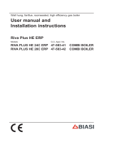
3.3 EXTERNAL SENSOR (fig. 13)
If there is an external sensor, the heating
settings SET can be taken from the climatic
curves according to the external tempera-
ture and, limited to with the range values
described in point 3.2 (parameters PAR 13
and PAR 14).
The climatic curve to be set can be selected
from a value of 3 and 40 (at step 1).
Increasing the steepness of the curves of
fig. 14 will increase the output temperature
as the external temperature decreases.
3.5 CARD FUNCTIONING
The electronic card has the following
functions:
– Antifreeze protection of the heating cir-
cuits.
– Ignition and flame detection system.
– Control panel setting for the power and
the gas for boiler functioning.
– Anti-jammed for the pump which is fed
for a few seconds (10”) after 48 hours of
inactivity.
– Chimney sweep function which can be
activated from the control panel.
– Temperature which can be shifted with
the external sensor connected.
– Automatic regulation of the ignition
power and maximum heating.
Adjustments are managed automatically
by the electronic card to guarantee maxi-
mum flexibility in use of the system.
3.6 TEMPERATURE
DETECTION SENSOR
Table 4 shows the resistance values of the
heating, D.H.W. and fumes sensor.
If the C.H. sensor (SM) and fumes sensor
(SF) is faulty or open circuit, the boiler
will not function on either heating or
D.H.W.
If the D.H.W. sensor (SS) is faulty or open
circuit, the boiler will function on either
heating and D.H.W. (ALL 10).
3.6 ELECTRONIC
IGNITION
Ignition and flame detection is controlled by
electrodes on the burner which guarantees
reaction in the case of accidental extinction
or lack of gas within one second.
3.6.1 Functioning cycle
Burner ignition should occur within 10
seconds of the opening of the gas valve. If
after three attempts the ignition is not
detected the boiler will lockout (ALL 06):
–Lack of gas
The ignition electrode will discharge for a
maximum of 10 seconds. If after three
attempts the ignition is not detected the
boiler will lockout (ALL 06).
This can happen the first time a boiler is
switched on, or after long periods of inac-
tivity. It can also be caused by a closed
gas cock or a gas valve not operating.
–No ionisation
The boiler will spark for 10 seconds, if
after 3 attempts the ionisation is not
detected, the boiler will lockout (ALL 06).
This could be due to a poor connection or
break in the ionisation cable.
Check also that the cable is not shorted,
badly worn or distorted.
In the case of a sudden loss of voltage, the
burner will immediately switch off. When
the voltage is restored, the boiler will auto-
matically start up again.
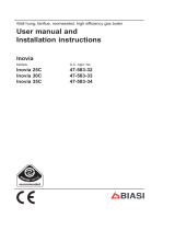
3.7 HEAD AVAILABLE
TO SYSTEM (fig. 14 )
Residual head for the heating system is
shown as a function of rate of flow in the
graph in fig. 14.
3.8 WATER PRESSURE
SWITCH (fig. 15)
The water pressure switch (8) intervenes,
blocking burner functioning, if it detects
that there is insufficient pressure in the
boiler (< 0,6 bar).
To restore the boiler operation, increase
the system pressure to 1 - 1,2 bar.
TABLE 4 (SM - SS - SF sensors)
Temperature (°C) Resistance (Ω)
20 12.090
30 8.313
40 5.828
50 4.161
60 3.021
70 2.229
80 1.669
Fig. 13
ATTENTION: curves are calculated at an ambient temperature of 20°C.
The user can act on the boiler controls to change the environment set
for which the bend has been calculated by ±5°C.

20
0
600
200 12001000800600400
PORTATA (l/h)
PREVALENZA RESIDUA (mbar)
500
400
100
200
300
MERIDIAN HE 25-30
HE 30 - HE 30 C
HE 25
PO RTATA PREVALENZA
(l/h) RESIDUA (mbar)
0512
100 500
200 487
300 468
400 443
500 412
600 377
700 338
800 294
900 246
1030 169
PO RTATA PREVALENZA
(l/h) RESIDUA (mbar)
0515
100 485
200 480
300 471
400 462
500 445
600 423
700 391
800 352
900 300
1050 222
HE 25 HE 30 - HE 30 C
Fig. 15
Fig. 14
RESIDUAL HEAD (mbar)
FLOW RATE (l/h)
KEY
1 Condensate drain trap
2 Diverter valve
3 D.H.W. exchanger
4 Gas valve
5 D.H.W. flow switch
6 Pressure relief valve
7 Pump with air release vent
8 Water pressure switch
9 Boiler discharge
10 D.H.W. sensor (SS)
1
2
3
4
6
5
7
8
9
10
FLOW RATE
(l/h)
FLOW RATE
(l/h)
RESIDUAL HEAD
(mbar)
RESIDUAL HEAD
(mbar)
Page is loading ...
Page is loading ...
Page is loading ...
Page is loading ...
Page is loading ...
Page is loading ...
Page is loading ...
Page is loading ...
Page is loading ...
Page is loading ...
Page is loading ...
Page is loading ...
Page is loading ...
Page is loading ...
Page is loading ...
Page is loading ...
Page is loading ...
Page is loading ...
Page is loading ...
Page is loading ...
Page is loading ...
Page is loading ...
Page is loading ...
Page is loading ...
Page is loading ...
Page is loading ...
Page is loading ...
Page is loading ...
/