

i
Contents
1 Introduction ........................................................................................................1
1.1 Safety Precautions ................................................................................1
1.2 LEDs and Interfaces..............................................................................2
1.3 System Requirements...........................................................................4
1.4 Features ................................................................................................4
2 Hardware Installation .........................................................................................5
3 About the Web Configuration.............................................................................8
3.1 Access the Router.................................................................................8
3.2 Status.....................................................................................................8
3.2.1 Device Info..................................................................................9
3.2.2 System Log.................................................................................9
3.2.3 Statistics....................................................................................10
3.3 Quick Start...........................................................................................11
3.4 Interface Setup....................................................................................15
3.4.1 Internet......................................................................................15
3.4.2 LAN...........................................................................................24
3.4.3 Wireless....................................................................................27
3.5 Advanced Setup..................................................................................29
3.5.1 Firewall .....................................................................................30
3.5.2 Routing .....................................................................................30
3.5.3 NAT...........................................................................................31
3.5.4 QoS...........................................................................................36
3.5.5 VLAN ........................................................................................39
3.5.6 ADSL ........................................................................................42
3.6 Access Management...........................................................................42
3.6.1 ACL...........................................................................................42
3.6.2 Filter..........................................................................................43
3.6.3 SNMP .......................................................................................47
3.6.4 UPnP ........................................................................................47
3.6.5 DDNS........................................................................................48
3.7 Maintenance........................................................................................49
3.7.1 Administration...........................................................................49
3.7.2 Time Zone.................................................................................50
3.7.3 Firmware...................................................................................51

GO-DSL-N150 User Manual
ii
3.7.4 SysRestart................................................................................52
3.7.5 Diagnostics...............................................................................53
3.8 Help.....................................................................................................54
3.8.1 Quick Start................................................................................54
3.8.2 Interface Setup .........................................................................54
3.8.3 Advanced Setup .......................................................................60
3.8.4 Access Management................................................................64
3.8.5 Maintenance.............................................................................65
3.8.6 Status........................................................................................66

GO-DSL-N150 User Manual
1
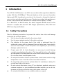
1 Introduction
The GO-DSL-N150 device is an ADSL access device that supports multiple line
modes. With four 10/100Base-T Ethernet interfaces at the user end, it provides
high-speed ADSL broadband connection to the Internet or Intranet for high-end
users such as net cafes and office users. The device provides high performance
access to the Internet with a downlink of 24 Mbps and an uplink of 1 Mbps.
As a WLAN AP or WLAN router, the device supports WLAN access to the
Internet. It complies with the IEEE 802.11b/g/n specifications, WEP, WPA and
WPA2 security specifications.
1.1 Safety Precautions
Take the following instructions to prevent the device from risks and damage
caused by fire or electric power:
Use the type of power marked by the volume label.
Use the power adapter packed in the device package.
Pay attention to the power load of the outlet or prolonged lines. An
overburden power outlet or damaged lines and plugs may cause electric
shock or fire accident. Check the power cords regularly. If you find any
damage, replace it at once.
Proper space left for heat dissipation is necessary to avoid damage
caused by overheating to the device. The long and thin holes on the device
are designed for heat dissipation to ensure that the device works normally.
Do not cover these heat dissipation holes.
Do not put this device close to a place where a heat source exists or high
temperature occurs. Avoid the device from direct sunshine.
Do not put this device close to a place where it is overdamp or watery. Do
not spill any fluid on this device.
Do not connect this device to any PCs or electronic products, unless our
customer engineer or your broadband provider instructs you to do this,
because any wrong connection may cause power or fire risk.
Do not place this device on an unstable surface or support.

GO-DSL-N150 User Manual
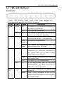
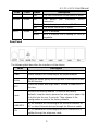
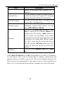
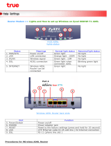
1.2 LEDs and Interfaces
Front Panel
The following table describes the LEDs of the device.
LEDs Color Status Description
On The device is powered on or the initiation of
the device is successful.
Green
Off The device is powered off.
Power
Red On The device is self-testing, the self-test is
failed or the software is upgrading.
On The device has established a connection
with the physical layer of the office end.
Slow
Blinks
No signal is being detected.
DSL Green
Fast
Blinks
The device is handshaking with the
physical layer of the office end.
On The device has a successful WAN
connection (PPP dial-up is successful) in
the routing mode and no data is being
transmitted on the Internet.
Blinks Data is being transmitted on the Internet in
the routing mode.
Green
Off The device is in the bridged mode.
Internet
Red On In the routing mode, after the successful
synchronization, the WAN connection is
failed (PPP dial-up is failed).
On The LAN connection is nomal and
activated.
LAN4/3
/2/1
Green
Blinks Data is being transmitted on the LAN or
data is being transmitted on the Internet in
the bridged mode.
2

GO-DSL-N150 User Manual
LEDs Color Status Description
Off The LAN connection of the device is failed.
On The device has successful WLAN
connection.
Blinks Data is being transmitted on WLAN.
WLAN Green
Off The WLAN connection is failed.
Off WPS is disabled. WPS Green
Blinks WPS is enabled, and is waiting for client to
negotiate.
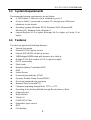
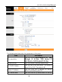
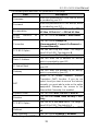
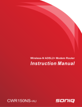
Rear Panel
The following table describes the interfaces of the device:
Items Description
Power switch for powering on/off the device.
Power
Power interface for connecting to the power adapter.
WLAN
Press the button gently and let go after 2 seconds to enable
WLAN function.
WPS
Press the button and let go after 1 second to enable WPS
function.
Reset
Reset to the factory defaults. To reset to the factory
defaults, keep the device powered on and push a paper clip
in to the hole for over 3 seconds. Then release it, the
configuration is reset to the factory defaults.
LAN4/3/2/1
RJ-45 interface for connecting to the Ethernet interface of
PC or other Ethernet devices through the Ethernet cable.
DSL
RJ-11 interface for connecting to the ADSL interface or a
splitter through the telephone cable.
3

GO-DSL-N150 User Manual
4
1.3 System Requirements
Recommended system requirements are as follows:
A 10/100 base-T Ethernet card is installed on your PC
A hub or Switch. (connected to several PCs through one of Ethernet
interfaces on the device)
Operating system: Windows 98 SE, Windows 2000, Windows ME,
Windows XP, Windows Vista, Windows 7
Internet Explorer V5.0 or higher, Netscape V4.0 or higher, or Firefox 1.5 or
higher
1.4 Features
The device supports the following features:
Various line modes
External PPPoE dial-up access
Internal PPPoE/PPPoA dial-up access
1483Bridged/1483Routed with dynamic ip or static ip
Multiple PVCs (the number of PVCs support is eight)
DHCP server/relay
Static route
Network Address Translation(NAT)
DMZ
Virtual Server
Universal plug and play (UPnP)
Dynamic Domain Name Server(DDNS)
One-level password and username
Network Time Protocol(NTP)
Firmware upgrading through Web, TFTP, or FTP
Resetting to the factory defaults through Reset button or Web
Diagnostic test
Web interface
Telnet CLI
IP/MAC/URL Filter
Application layer service
QOS
Port binding

GO-DSL-N150 User Manual
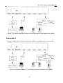
2 Hardware Installation
Step 1 Connect the DSL interface of the device and the Modem interface of
the splitter through a telephone cable. Connect the phone to the
Phone interface of the splitter through a cable. Connect the incoming
line to the Line interface of the splitter.
The splitter has three interfaces:
Line: Connect to a wall phone jack (RJ-11 jack).
Modem: Connect to the ADSL jack of the device.
Phone: Connect to a telephone set.
Step 2 Connect the LAN interface of the device to the network card of the PC
through an Ethernet cable (MDI/MDIX).
Note:
Use twisted-pair cables to connect with the hub or switch.
Step 3 Plug one end of the power adapter to the wall outlet and connect the
other end to the Power interface of the device.
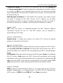
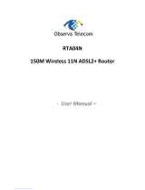
Connection 1
Figure 1 shows the application diagram for the connection of the router, PC,
splitter and the telephone sets, when no telephone set is placed before the
splitter.
5


GO-DSL-N150 User Manual
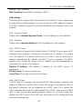
Note:
When connection 2 is used, the filter must be installed close to the telephone
cable. See Figure2. Do not use the splitter to replace the filter.
Installing a telephone directly before the splitter may lead to failure of
connection between the device and the central office or failure of Internet
access or slow connection speed. If you really need to add a telephone set
before the splitter, you must add a microfilter before a telephone set. Do not
connect several telephones before the splitter or connect several telephones
with the microfilter.
7

GO-DSL-N150 User Manual
3 About the Web Configuration
This chapter describes how to configure the router by using the Web-based
configuration utility.
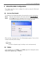
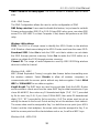
3.1 Access the Router
The following is the detailed description of accessing the router for the first time.
Step 1 Open the Internet Explorer (IE) browser and enter http://192.168.1.1
.
Step 2 In the Login page that is displayed, enter the username and password.
The username and password of the user are admin and 1234.
When you log in, the page shown in the following figure appears. You can check,
configure and modify all the settings.
Note:
In the Web configuration page, the settings can be saved permanently.
3.2 Status
In the navigation bar, click Status. In the Status page that is displayed contains
Device Info, System Log and Statistics.
8

GO-DSL-N150 User Manual
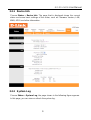
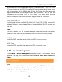
3.2.1 Device Info
Choose Status > Device Info. The page that is displayed shows the current
status and some basic settings of the router, such as Firmware Version, LAN,
WAN, ADSL and other information.
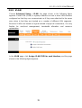
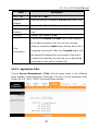
3.2.2 System Log
Choose Status > System Log, the page shown in the following figure appears.
In this page, you can view or refresh the system log.
9

GO-DSL-N150 User Manual
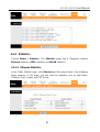
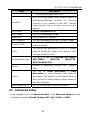
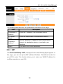
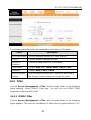
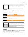
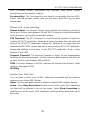
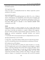
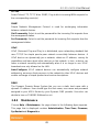
3.2.3 Statistics
Choose Status > Statistics. The Statistics page that is displayed contains
Ethernet Statistics, ADSL Statistics and WLAN Statistics.
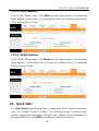
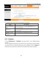
3.2.3.1 Ethernet Statistics
In the Traffic Statistic page, click Ethernet and the page shown in the following
figure appears. In this page, you can view the statistics such as total Bytes,
Collision, Error Frames and CRC Errors.
10

GO-DSL-N150 User Manual
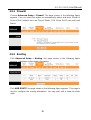
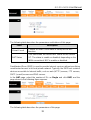
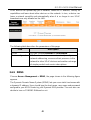
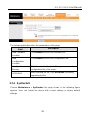
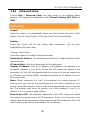
3.2.3.2
ADSL Statistics
In the Traffic Statistic page, click ADSL and the page shown in the following
figure appears. In this page, you can view the ADSL line statistics such as total
PDUs and total Error Counts.
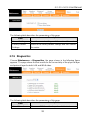
3.2.3.3 WLAN Statistics
In the Traffic Statistic page, click WLAN and the page shown in the following
figure appears. In this page, you can view the statistics such as Transmitted
Frame, Errors or Drops.
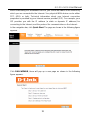
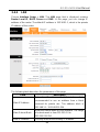
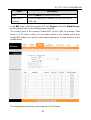
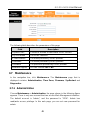
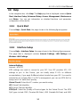
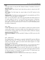
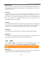
3.3 Quick Start
The Quick Start page will guide you to configure the ADSL router to connect to
your ISP (Internet Service Provider). The following sections describe these
various configuration parameters. Whether you configure these parameters or
use the default ones, click NEXT to enable your Internet connection.
11

GO-DSL-N150 User Manual
When subscribing to a broadband service, you should be aware of the method by
which you are connected to the Internet. Your physical WAN device can be either
PPP, ADSL or both. Technical information about your Internet connection
properties is provided by your Internet service provider (ISP). For example, your
ISP provides you with the IP address (a static or dynamic IP address) for
connecting to the Internet, and the protocol for communication on the Internet.
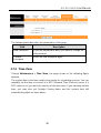
In the navigation bar, click Quick Start. The page as shown in the following figure
appears.
Click RUN WIZARD, there will pop up a new page as shown in the following
figure appears.
12

GO-DSL-N150 User Manual
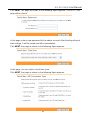
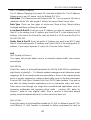
Click NEXT, the page as shown in the following figure appears. Click EXIT, this
page will be closed.
In this page, enter a new password for the admin account. After finishing all quick
start settings, it will be saved and effect immediately.
Click NEXT, the page as shown in the following figure appears.
In this page, you can select a local time zone.
Click NEXT, the page as shown in the following figure appears.
13

GO-DSL-N150 User Manual
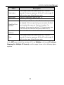
There are five WAN connection types: Auto setup by ISP list, Dynamic IP
Address, Static IP Address, PPPoE/PPPoA and Bridge Mode. Select the
appropriate wan connection type which is provided by your ISP.
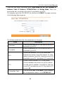
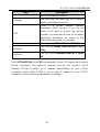
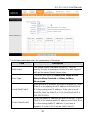
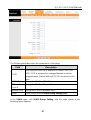
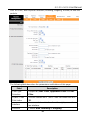
For example, select the PPPoE/PPPoA, and then click NEXT, the page as shown
in the following figure appears.
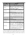
The following table describes the parameters in this page:
Field Description
Username
Enter the username for PPPoE dial-up, which is
provided by your ISP.
Password
Enter the password for PPPoE dial-up, which is
provided by your ISP.
VPI
Virtual path identifier (VPI) is the virtual path
between two points in an ATM network. Its valid
value is between 0 and 255. Enter the correct VPI
provided by your ISP. By default, VPI is set to 0.
VCI
Virtual channel identifier (VCI) is the virtual
channel between two points in an ATM network.
Its valid value is between 1 and 65535. Enter the
correct VCI provided by your ISP. By default, VCI
is set to 33.
Connection Type
You can select LLC or VC-Mux. In this example,
the encapsulation mode is set to PPPoE LLC.
14

GO-DSL-N150 User Manual
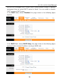
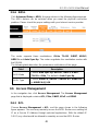
After setting, click NEXT, the page as shown in the following figure appears.
Click BACK to modify the settings.
Click NEXT to save the settings.
Click EXIT to cancel the settings.
Note:
After you saving the settings in the Quick Start page, you can view this wan
connection settings in the Interface Setup > Internet page.
3.4 Interface Setup
In the navigation bar, click Interface Setup. The Interface Setup page that is
displayed contains Internet, LAN and Wireless.
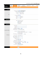
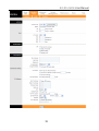
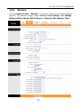
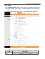
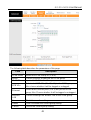
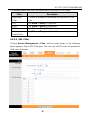
3.4.1 Internet
Choose Interface Setup > Internet. The Internet page that is displayed contains
ATM VC, Qos and Encapsulation. In this page, you can configure WAN
interface of your router.
15

GO-DSL-N150 User Manual
16

GO-DSL-N150 User Manual
17
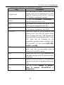
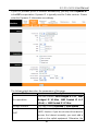
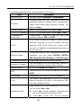
The following table describes the parameters of this page:
Field Description
Virtual Circuit
You can select a virtual circuit from the
drop-list. Click PVCs Summary you can view
eight PVCs (from PVC0 to PVC7), and only
PVC0 status is activated by default.
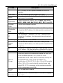
Status
You can select Activated or Deactivated for
currently selected virtual circuit.
VPI
The virtual path between two points in an
ATM network, ranging from 0 to 255.
VCI
The virtual channel between two points in an
ATM network, ranging from 1 to 65535.
ATM QoS Select the Quality of Service types for this
Virtual Circuit. The ATM QoS types include
CBR (Constant Bit Rate), VBR (Variable Bit
Rate) and UBR (Unspecified Bit Rate). These
QoS types are all controlled by the
parameters specified below, including PCR,
SCR and MBS. You can choose CBR, UBR,
rt-VBR or nrt-VBR.
PCR Peak cell rate (PCR) is the maximum rate at
which cells can be transmitted along a
connection in the ATM network.
SCR Sustain cell rate (SCR) is the maximum rate
that traffic can pass over PVC without the risk
of cell loss.
MBS Maximum burst size (MBS) is the maximum
number of cells that can be transmitted at the
PCR.
ISP
You can choose Dynamic IP Address,
Static IP Address, PPPoA/PPPoE or
Bridge Mode.
Page is loading ...
Page is loading ...
Page is loading ...
Page is loading ...
Page is loading ...
Page is loading ...
Page is loading ...
Page is loading ...
Page is loading ...
Page is loading ...
Page is loading ...
Page is loading ...
Page is loading ...
Page is loading ...
Page is loading ...
Page is loading ...
Page is loading ...
Page is loading ...
Page is loading ...
Page is loading ...
Page is loading ...
Page is loading ...
Page is loading ...
Page is loading ...
Page is loading ...
Page is loading ...
Page is loading ...
Page is loading ...
Page is loading ...
Page is loading ...
Page is loading ...
Page is loading ...
Page is loading ...
Page is loading ...
Page is loading ...
Page is loading ...
Page is loading ...
Page is loading ...
Page is loading ...
Page is loading ...
Page is loading ...
Page is loading ...
Page is loading ...
Page is loading ...
Page is loading ...
Page is loading ...
Page is loading ...
Page is loading ...
Page is loading ...
Page is loading ...
-
 1
1
-
 2
2
-
 3
3
-
 4
4
-
 5
5
-
 6
6
-
 7
7
-
 8
8
-
 9
9
-
 10
10
-
 11
11
-
 12
12
-
 13
13
-
 14
14
-
 15
15
-
 16
16
-
 17
17
-
 18
18
-
 19
19
-
 20
20
-
 21
21
-
 22
22
-
 23
23
-
 24
24
-
 25
25
-
 26
26
-
 27
27
-
 28
28
-
 29
29
-
 30
30
-
 31
31
-
 32
32
-
 33
33
-
 34
34
-
 35
35
-
 36
36
-
 37
37
-
 38
38
-
 39
39
-
 40
40
-
 41
41
-
 42
42
-
 43
43
-
 44
44
-
 45
45
-
 46
46
-
 47
47
-
 48
48
-
 49
49
-
 50
50
-
 51
51
-
 52
52
-
 53
53
-
 54
54
-
 55
55
-
 56
56
-
 57
57
-
 58
58
-
 59
59
-
 60
60
-
 61
61
-
 62
62
-
 63
63
-
 64
64
-
 65
65
-
 66
66
-
 67
67
-
 68
68
-
 69
69
-
 70
70


Ask a question and I''ll find the answer in the document
Finding information in a document is now easier with AI
Related papers
Other documents
-
 ZyXEL Communications Prestige 600 Series User manual
-
 Soniq CWR150NS-AU Owner's manual
-
Binatone DT820N Quick Installation Manual
-
-
Planet ADN-4100 Owner's manual
-
 Observa Telecom RTA04N User manual
-
Digisol DG-VG2300N User manual
-
 Starbridge Networks Lynx 524 User manual
-
 Baytec RTA04N Owner's manual
-
 Innoband 8520-B1 Owner's manual


