Page is loading ...

INSTALLATION AND MAINTENANCE MANUAL
for
MODEL 174100
ASR 11 S-BAND ANTENNA
MANUAL No. 79680
REVISION AD
22 October 2003
ANDREW CANADA INC.
606 BEECH STREET, WHITBY
ONTARIO, CANADA
L1N 552
79680.AD.DOC

2
LIST OF EFFECTIVE PAGES
Dates of original issue and revisions are:
Original ........... A........... 26 January 1997
Revision .......... B .......... 19 February 1998
Revision .......... C ........... 9 March 1998
Revision .......... D........... 28 May 1998
Revision ......... F ........... 19 JUNE 1998
Revision ......... F ........... 16 JULY 1998
Revision .......... G .......... 9 NOVEMBER 1998
Revision .......... H........... 01 DECEMBER 1998
Revision ......... J ............ 23 DECEMBER 1998
Revision .......... K........... 13 APRIL 1999
Revision .......... L ........... 04 JUNE 1999
Revision .......... M .......... 13 OCTOBER 1999
Revision ......... N........... 05 JANUARY 2000
Revision .......... P ........... 24 MARCH 2000
Revision .......... R ........... 30 JANUARY 2001
Revision .......... T ........... 26 FEBRUARY 2001
Revision ......... U........... 04 OCTOBER 2001
Revision .......... V........... 21 MAY 2002
Revision .......... W .......... 29 JULY 2002
Revision ......... Y........... 15 JAN 2003
Revision .......... Z. .......... 30 APRIL 2003
Revision .......... AA. ....... 14 MAY 2003
Revision ......... AB ........ 05 AUGUST 2003
Revision .......... AC ........ 07 October 2003
Revision .......... AD ........ 22 October 2003
PAGE REVISION
Title Page AD
List of Effective Pages AD
Safety Summary AD
Table of Contents AD
Section 1 - General Description and Theory of Operation AD
Section 2 - Equipment Receipt, Unpacking and Lifting AD
Section 3 - Installation Procedures AD
Section 4 - Maintenance AD
Section 5 - Other Equipment AD
Section 6 - Optional Equipment AD

3
SAFETY SUMMARY
GENERAL:
READ THE INSTRUCTION THOROUGHLY BEFORE ASSEMBLY. FOLLOW THE
SEQUENCES FOR PROPER. ASSEMBLY AND OPERATION.
NOTICE:
THE INSTALLATION, MAINTENANCE OR REMOVAL OF THE ANTENNA REQUIRES
QUALIFIED, EXPERIENCED PERSONNEL. ANDREW INSTALLATION INSTRUCTIONS HAVE
BEEN WRITTEN AND ILLUSTRATED FOR SUCH INSTALLATION PERSONNEL. THIS SYSTEM
SHOULD BE INSPECTED ONCE A YEAR BY QUALIFIED PERSONNEL TO VERIFY PROPER
INSTALLATION, MAINTENANCE AND CONDITION OF EQUIPMENT. ANDREW DISCLAIMS
ANY LIABILITY OR RESPONSIBILITY FOR THE RESULTS OF IMPROPER OR UNSAFE
INSTALLATION OR MAINTENANCE PRACTICES.
220 VAC, THREE PHASE POWER IS USED IN THE OPERATION OF THIS EQUIPMENT THAT IS
DANGEROUS AND MAY BE FATAL IF CONTACTED BY PERSONNEL. EXTREME CAUTION
SHOULD BE EXERCISED WHEN WORKING WITH THIS EQUIPMENT. WHILE EVERY
PRACTICABLE SAFETY PRECAUTION HAS BEEN INCORPORATED IN THIS EQUIPMENT, THE
FOLLOWING RULES MUST BE STRICTLY OBSERVED.
KEEP AWAY FROM LIVE CIRCUITS:
Operators and maintenance personnel must at all times observe safety regulations. Do not change plug-in
components or make adjustments inside the equipment with high voltage supply on. Under certain conditions
dangerous potentials may exist in circuits with the power control in the OFF position due to charges retained
by capacitors. To avoid casualties always remove power, then discharge and ground by use of a ground rod,
prior to touching any parts.
- Do not remove covers or access plates on the equipment unless you are authorized to do so.
- Do not work on electronic equipment unless there is another person nearby who is familiar with the
operation of the equipment and is trained in administering first aid.
- To prevent electrical shock or damage to the equipment, do not operate it until you thoroughly understand the
operation and function of all controls, indicators and connectors.

4
FIRST AID
In case of electrical shock:
Do not try to pull or grab the individual.
If possible, turn off the electrical power.
If you cannot turn off the electrical power, pull, push, or lift the person to safety using a dry wooden pole, a
dry rope, or some other insulating material.
Send for help as soon as possible.
After the injured person is no longer in contact with the source of electrical shock, move the person a short
distance away and immediately administer first aid and artificial resuscitation as required.

5
TABLE OF CONTENTS
Paragraph Title Page
1 General Description and Theory of Operation................................................................ 9
1.1 Scope .............................................................................................................................. 9
1.2 Purpose of Equipment ..................................................................................................... 9
1.3 Equipment Supplied ........................................................................................................ 9
1.4 Physical Description ...................................................................................................... 9
1.4.1 Antenna ........................................................................................................................... 9
1.5 Functional Description .................................................................................................. 10
1.5.1 Antenna Unit ................................................................................................................. 10
1.5.1.1 Reflector ....................................................................................................................... 10
1.5.1.2 Dual Feed Assembly ..................................................................................................... 10
1.5.2 Polarization and Beamswitch Box ................................................................................ 10
1.6 Theory of Operation ..................................................................................................... 11
1.6.1 Dual Feed Assembly ..................................................................................................... 11
1.6.2 Reflector ....................................................................................................................... 11
1.6.3 Detailed Circuit Analysis .............................................................................................. 11
1.6.3.1 Antenna Unit ................................................................................................................. 11
1.6.3.2 Azimuth Antenna Pattern ............................................................................................. 12
1.6.3.3 Elevation Patterns ......................................................................................................... 12
1.63.4 Other Antenna Specifications ....................................................................................... 12
1.6.3.5 Antenna Reflector ......................................................................................................... 12
1.6.3.6 Reflector Mounting and Tilt Adjustment ...................................................................... 13
1.6.4 Dual Feed Assembly ..................................................................................................... 13
1.6.4.1 Feed Assembly.............................................................................................................. 13
1.6.4.2 Circular Polarization Generation .................................................................................. 13
1.6.4.3 Transmitting Circularly Polarized Signals .................................................................... 14
1.6.4.4 Receiving Circularly Polarized Signals ........................................................................ 14
1.6.4.5 Transmitting and Receiving Linearly Polarized Signals .............................................. 15
1.6.4.6 Feedhorn Assembly ...................................................................................................... 15
1.6.4.7 Polarizer/Feed Assembly Mechanical Operation.......................................................... 15

6
2 Equipment Receipt, Unpacking and Lifting................................................................. 21
2.1 Receipt ......................................................................................................................... 21
2.2 Unpacking .................................................................................................................... 21
2.3 Lifting .......................................................................................................................... 24
3 Installation Procedures ................................................................................................. 25
3.1 Introduction .................................................................................................................. 25
3.1.1 Overview ...................................................................................................................... 25
3.1.2 Recommended System Assembly Tool List ................................................................ 27
3.2 Standard Torque Values for Assembly ........................................................................ 29
3.3 Summary of Installation Sequence .............................................................................. 30
3.3.1 Installing the Base Interface Kit ................................................................................... 31
3.3.2 Installing the Fixed Feeds Unit to the Reflector Base .................................................. 34
3.3.3 Installing the Ladder Kit .............................................................................................. 36
3.3.3.1 Access Ladder General Climbing Procedure ............................................................... 40
3.3.4 Installing the PSR/SSR Interface Mount ..................................................................... 43
3.3.4.1 Installing the SSR Tilt Scale Bracket ........................................................................... 44
3.3.5 Lifting the Assembly .................................................................................................... 46
3.3.6 Leveling the Antenna Assembly .................................................................................. 50
3.3.7 Installing the Polarization and Beamswitch Control Box ............................................ 51
3.3.8 Installing the AC Junction Box .................................................................................... 51
3.3.9 Adjusting the Antenna Azimuth .................................................................................. 51
3.3.10 Installing the Waveguide ............................................................................................. 51
3.3.11 Installing the Coaxial and Electrical Cables ................................................................ 56
33.11.1 PSR Coaxial and Electrical Cables .............................................................................. 57
3.3.11.2 SSR Coaxial Cables ..................................................................................................... 59
3.3.11.3 Grounding Cable .......................................................................................................... 59
33.12 Performing Final Readiness Check .............................................................................. 62
33.12.1 Antenna Feedhorn Alignment Check, ......................................................................... 62
3.3.12.2 Contour Damage Check ............................................................................................... 63
3.3.13 Installing the Feed Counterweights to the Fixed Feeds Unit.. ..................................... 64
33.14 Installing the Antenna Counterweights ........................................................................ 64
4 Maintenance ................................................................................................................. 68
4.1 General Procedures ...................................................................................................... 68
4.1.1 Maintenance Precautions ............................................................................................. 68
4.1.2 Standard Maintenance Procedures ............................................................................... 69

02/08/2016 SDR-ASR11-052
TI 6310.59
7
4.2 Preventive Maintenance ............................................................................................... 70
4.3 Disassembly Procedures ............................................................................................... 72
4.3.1 Disassembly of the Dual Feed Assembly ..................................................................... 72
4.3.2 Polarization and Beamswitch Control Box (174170)
Removal and Replacement Procedure .......................................................................... 74
4.3.3 Removal and Replacement of Antenna Ladder Slides ............................................... 74d
5 Other Equipment ........................................................................................................... 79
5.1 Test Antenna Kit ........................................................................................................... 79
6 Optional Equipment ...................................................................................................... 82
6.1 Obstruction Lighting Kit .............................................................................................. 82
6.2 Radome Kit ................................................................................................................... 84
LIST OF TABLES
Table Title Page
2-1 Weights of Major Antenna Components ................................................................................. 24
3-1 Installation Kit (174225) ......................................................................................................... 26
3-2 Shipping and Support Stand Kit .............................................................................................. 27
3-3 Installation Equipment ............................................................................................................. 27
3-4 Standard Torque Values for Assembly .................................................................................... 29
3-5 Base Interface Kit Materials (174198) ................................................................................... 32
3-6 Fixed Feeds Unit-to-Reflector Base Installation Materials ..................................................... 34
3-7 Ladder Kit Installation Materials (174180) ............................................................................. 36
3-8 PSR/SSR Interface Mount and Tilt Scale Bracket Installation Materials ................................ 43
3-9 Antenna Lift Kit Installation Materials (174245) .................................................................... 46
3-10 Rotary Joint-to-Dual Feed Waveguide Installation Materials (174247) .................................. 52
3-11 Coaxial and Electrical Cable Installation Materials ................................................................ 56
3-12 Telescope Mounting Installation Materials ............................................................................. 62
4-1 Common Support Equipment .................................................................................................. 69
4-2 Line Replaceable Units (LW) and ........................................................................................... 78
Preventative and Corrective Maintenance Kits
5-1 Test Antenna Kit ...................................................................................................................... 79
6-1 Obstruction Lighting Kit ......................................................................................................... 82
6-2 Radome Kit .............................................................................................................................. 84
*
*

02/08/2016 SDR-ASR11-052
TI 6310.59
8
LIST OF ILLUSTRATIONS
Figure Title Page
1-1 Typical Antenna Pattern, Azimuth .......................................................................................... 17
1-2 Typical Antenna Pattern, Elevation ......................................................................................... 18
1-3 Polarizer Schematic ................................................................................................................. 19
1-4 Antenna Schematic Diagram ................................................................................................... 20
3-1 Complete Antenna Installation ................................................................................................ 22
3-2 Shipping and Support Stand .................................................................................................... 23
3-3 Base Interface-PSR Base Assembly ........................................................................................ 33
3-4 Fixed Feeds Unit Installation ................................................................................................... 35
3-5 Ladder Kit Installation ............................................................................................................. 42
3-6 PSR/SSR Interface Mount Installation .................................................................................... 45
3-7 Antenna Lift Kit Installation .................................................................................................... 49
3-8 Waveguide Installation ............................................................................................................ 54
3-9 Waveguide Hanger Installation ............................................................................................... 55
3-10 Coaxial and Electrical Cable Installation ................................................................................ 60
Polarization and Beamswitch Control Box Installation ........................................................... 60
AC Junction Box Installation................................................................................................... 60
3-11 SSR Coaxial Cable and Tilt Scale Bracket Installation ........................................................... 61
3-12 Antenna Feedhorn and Tilt Alignment and Contour Check .................................................... 65
3-13 Antenna Azimuth Alignment ................................................................................................... 66
3-14 Counterweight Installation....................................................................................................... 67
4a Polarization and Beamswitch Control Box Location on Antenna ........................................... 74
4b Polarization and Beamswitch Control Box Close Up ............................................................ 74b
4c Lower Antenna Ladder Slide ................................................................................................ 74f
4-1 Polarizer ................................................................................................................................... 76
4-2 Polarizer Motor Replacement .................................................................................................. 77
5-1 Test Antenna Kit ...................................................................................................................... 81
6-1 Obstruction Lighting Kit ......................................................................................................... 83
*
*

9
SECTION 1
1. GENERAL DESCRIPTION and THEORY OF OPERATION
1.1 SCOPE
This instruction book contains theory of operation and information for the installation, operation and
maintenance of the Primary Surveillance Radar S-Band Antenna (ASR 11).
1.2 PURPOSE OF EQUIPMENT
The S-Band reflector type antenna, called the Primary Surveillance Radar (PSR) Antenna is used in
transmitting and receiving RF energy for Air Traffic control and for supporting a Large Vertical
Aperture (LVA) Secondary Surveillance Radar (SSR) Antenna.
1.3 EQUIPMENT SUPPLIED
The antenna assembly consists of the equipment, subassemblies and kits listed in Table 3-1. Figure
3-1 shows the complete Antenna assembly.
1.4 PHYSICAL DESCRIPTION
The antenna assembly uses materials, coatings and finishes inherently resistant to corrosive
environment. Intended as the strongest link in the radar system, the antenna requires minimum
maintenance. It is designed to facilitate removal and replacement of any faulty portion except the
reflector and pedestal with equipment furnished as part of the system.
1.4.1 Antenna
The antenna unit, having no standby assembly, is designed to be highly reliable and capable of
withstanding adverse weather conditions. Aluminum construction is used throughout, except the
base, feed support, horn radomes, etc., that require other materials. Special paints are used to give the
assembly maximum life, even in regions where air is heavily polluted.

10
1.5 FUNCTIONAL DESCRIPTION
The antenna radiates a beam 1.5 degrees in azimuth and shaped in elevation to produce coverage up
to approximately 32 degrees above the horizon to provide a map-type presentation of aircraft within
55 nautical miles of the airport terminal. Major assemblies of the antenna are described in the
following paragraphs. This section gives only a brief description of the function performed by each
without regard to functional operation. A detailed analysis of functional operation is contained in
Section 1.6, Theory of Operation.
1.5.1 Antenna Unit
The antenna unit consists of Reflector, Dual Feed Assembly, interconnecting waveguide, cables and
wires. The antenna produces a rotating antenna pattern having a 1.5 degree azimuth beamwidth and a
shaped elevation pattern allowing radar coverage up to 32 degrees above the horizon. Polarization of
the radiated energy can be remotely switched to either linear or circular polarization. Special
equipment includes a test antenna and a telescope used to check antenna alignment.
1.5.1.1 Reflector
The reflector has a modified parabolic shape designed to produce an approximately cosecant-squared
beam in the elevation plane. The reflecting surface, covered with expanded aluminum screen, is 16.1
feet wide and 9 feet high. The horizontal and vertical contour plates are fabricated using numerically
controlled equipment to ensure the required high degree of accuracy. Wind loads are transferred to
the reflector support through the base of the reflector and the back structure which consists of welded
aluminum tubes and channels.
1.5.1.2 Dual Feed Assembly
The dual feed assembly includes two identical polarizer/feed assemblies. Each polarizer/feed
assembly contains a square waveguide section with the necessary motor and gearing to generate
either linear or circular polarization as selected by the radar operator. The antenna feedhorn, which
mounts on the polarizer, provides impedance matching between the waveguide system and free
space, and produces the desired feed pattern to illuminate the reflector. A radome over the horn
aperture excludes moisture and foreign matter, and provides a pressure seal.
1.5.2 Polarization and Beamswitch Control Box
The Control Box mounted on the feed support provides for interconnection between the antenna unit
and the Rotary Joint connections.

11
1.6 THEORY OF OPERATION
The theory of operation for the antenna contains theory of operation for microwave and electronic
circuits and provides detailed circuit descriptions explaining circuit arrangements in the order of
operational or signal sequence. Functional operation of mechanical assemblies is provided as needed
and as related to electronic circuits and system operation.
1.6.1 Dual Feed Assembly
The dual feed assembly allows remote selection of linear or circular polarization and provides two
secondary antenna patterns displaced approximately 3.5 degrees in the elevation plane. (Secondary
patterns are those produced by the reflector, using primary patterns produced by the feedhorns.)
Under normal operating conditions linear polarization of the radiated signal will be used since it
provides higher level target returns. Under inclement weather conditions circular polarization can be
selected to reduce the radar sensitivity to clouds and precipitation.
Both feeds in this assembly are identical in construction. The normal or active feed (Low Beam) is
located above the passive feed (High Beam) to produce a secondary active beam directed more
toward the ground than the passive beam. The transmitted signal is radiated by this lower beam.
During the high ground clutter return period, the first 10 or 15 nautical miles, signals from the upper
beam (lower feed) are coupled to the receiver by means of a beam select switch located in the
receiver. This arrangement reduces the ground level returns without reducing returns from targets at
higher elevation angles.
1.6.2 Reflector
The reflector focuses RF energy to provide beams approximately 1.5 degrees in azimuth and shaped
in elevation to produce coverage up to approximately 32 degrees. The reflector surface has a circular
opening at the center for mounting a test antenna. The top of the reflector has provision for
supporting an LVA SSR antenna.
1.6.3 Detailed Circuit Analysis
1.6.3.1 Antenna Unit
The antenna, rotating at a rate of 12.5 r/min, scans an area with a radius of 55 nautical miles, using
two beams approximately 1.5 degrees in azimuth with shaped elevation patterns to provide coverage
up to 32 degrees. By selecting returns from the higher beam during the first part of the receive
period, ground clutter is reduced while good sensitivity is maintained for the rest of the coverage
volume. Each subassembly is discussed in the following paragraphs.

12
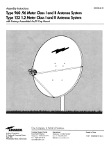
1.6.3.2 Azimuth Antenna Pattern - (See Figure 1-1 for Typical Azimuth Pattern.)
In the principal azimuth plane the antenna has a minimum azimuth beamwidth of 1.35 degrees at the
-3 dB power point and a maximum beamwidth at the -20 dB power point of 4 degrees; sidelobe level
is -24 dB for the Lowbeam and -22 dB for the Highbeam. For the Lowbeam at 30 degrees above the
elevation peak of the beam, the -3 d13 beamwidth is 1.35 degrees minimum and 5.5 degrees
maximum at the -15 dB power point; the maximum azimuth sidelobe level is -16 dB. For the
Highbeam at 28 degrees above the peak of the beam, the -3 dB beamwidth is 1.35 degrees minimum
and 6 degrees maximum at the -15 dB power point; the maximum sidelobe level is -15 dB. At a point
on the ground side of the peak of the passive pattern that is 20 dB below the maximum power point,
the -3 dB azimuth beamwidth is 1.1 degrees minimum and 3 degrees maximum at the -10 dB power
point. The maximum backlobe power level is -32 c113 for both beams at all elevation angles.
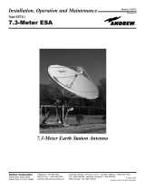
1.6.3.3 Elevation Patterns - (See Figure 1-2 for Typical Elevation Pattern.)
The elevation patterns have a 4.8 degree minimum -3 dB beamwidth and approximately a cosecant
squared power pattern up to 30 degrees above the peak of the normal pattern and 28 degrees above
the passive pattern. On the ground side of the peak-of-beam the pattern is down more than 20 dB
relative to the peak power point of each respective pattern at an angle of 4.1 degrees (active) and 5.1
degrees (passive) below the lower -3 dB elevation pattern power point With the antenna set so that it
is horizontal mechanically, the peak of the normal and passive beams are at approximately 2.0 and
5.7 degrees respectively. The two values will vary slightly from antenna to antenna.
1.6.3.4 Other Antenna Specifications
The peak-of-beam antenna gain is 33.5 d13 (Lowbeam) and 32.5 (Highbeam) above an isotropic
source. The principal elevation and azimuth plane ICR (rain clutter rejection) is 22 dB minimum.
The input VSWR of each feed is better than 1.3:1 over the entire operating frequency range of 2700
to 2900 MHz. The antenna is capable of operating in winds up to 85 knots and will withstand winds
up to 130 knots non-operational.
1.6.3.5 Antenna Reflector
The reflector is formed by contour plates riveted together to form a support structure onto which a
reflecting surface of expanded aluminum is welded. The basic accuracy of the reflecting surface is
determined by the contour plates which are fabricated by numerically controlled machines. A welded
backstructure, consisting of aluminum tubes and channels, aids in transferring windloads into the
reflector support. A section of screen in the center of the reflector is removable so a test antenna can
be mounted to check electrical characteristics of the dual feed. Three discs attached to the reflector
form targets used to check feed location. The top of the reflector forms a mounting pad for the LVA
SSR antenna.

13
1.6.3.6 Reflector Mounting and Tilt Adjustment
The reflector is mounted directly on the reflector support which is attached to the pedestal by two
hinged joints and two elevation tilt screws. The dual feed assembly with its associated waveguide
and related hardware is supported on a feed support which is mounted to the antenna base, causing
both the reflector and the dual feed assembly to tilt as necessary to achieve the desired elevation tilt
angle for the rotating beam. Adjusting the tilt screw is a manual operation, requiring only a few
minutes at the antenna platform. Antenna tilt is adjustable so that the peak of the main beam can be
set at any angle between 3.0 degrees below and 5.0 degrees above the horizontal. A pointer and
scale, marked in increments of 0.1 degree, indicate the elevation angle of the beam peak to an
accuracy of 0.2 degrees at the center of the frequency band. If an accuracy better than 0.2 degrees is
required, the use of an inclinometer is recommended for a more accurate reading of antenna tilt
adjustment. A tilt instruction plate mounted on the reflector support near the tilt screw provides
antenna tilt correction data as a function of frequency.
1.6.4 Dual Feed Assembly
Dual feed assembly (Figure 3-4) consists of two identical polarizer assemblies, transducers,
transitions to type >N=, two feedhorns, two radomes, and associated supporting hardware. Both
feeds are held in place by a mounting frame. Feed positioning is established during pattern testing
by Andrew. After positioning, locating pins are installed to permit proper realignment if field
disassembly/reassembly of the feed assembly is required. The dual feed assembly is attached to the
feed support arm of the reflector support by three large diameter threaded rods. All but the top three
nuts, which are self-locking, are pinned after antenna test to ensure proper location of the dual feed
assembly. Removal of the top three nuts is required to remove the dual feed assembly.
1.6.4.1 Feed Assembly
Figure 3-4 shows the relative positions of the subassemblies in one feed assembly. These are a dual-
mode transducer, a phase-shift section, a feedhorn and a transition.
1.6.4.2. Circular Polarization Generation
To obtain a circularly polarized signal the linearly polarized input signal is split into two equal,
orthogonally polarized (polarized perpendicular to each other) components. One of the signals is
then shifted in time 90 degrees relative to the other. The phase-shift section (polarizer) provides the
differential 90-degree phase shift for circular polarization and 0-degree phase shift for linear
polarization. Phase-shifter orientation with respect to the transducer (approximately 45 degrees)
determines relative amplitude of orthogonally polarized signals.

14
1.6.43 Transmitting Circularly Polarized Signals
A linear vertically polarized signal enters the transducer vertical port. The signal then passes through
an impedance matching section in the transducer and enters the phase shift section. The phase shifter
is rotated approximately 45 degrees about the longitudinal axis of the waveguide run. At this point
the signal can be considered to consist of two orthogonally polarized signals, each polarized parallel
to the walls of the square waveguide. As the dielectric vanes are moved in the phase-shift section,
the phase of the E-field component perpendicular to the plane of the vanes is unchanged; however,
the orthogonal component is changed in phase. By positioning the dielectric vanes approximately 0.9
inches from the waveguide wall, a 90-degree phase differential is created between the two signals,
producing circular polarization. The circularly polarized signal passes through the feedhorn,
illuminating the reflector which forms the desired radiation pattern.
1.6.4.4 Receiving Circularly Polarized Signals
Returns resulting from precipitation are reverse-sense circularly polarized. They enter the polarizer,
pass through the phase-shift section, and enter the dual-mode transducer as horizontally polarized
signals. These signals are coupled through the dual-mode transducer horizontal port via a transition
to type >N= and a coaxial cable to a Beamswitch. The Beamswitch allows either the low beam or
high beam precipitation return to be lead to the weather channel of the antenna. Precipitation returns
are thus diverted from the regular return path. Desired returns are circularly polarized in the same
sense as the transmitted signal. They are converted to vertical polarization by the phase-shift section
and enter the dual-mode transducer vertical port. These signals then pass through connecting
waveguide to the receiver.
The above applies when the antenna is operated in the circular polarization mode. One of the features
of this antenna is that in the linear polarization mode (see Section 1.6.4.5) a small circular component
is also transmitted together with the vertically polarized signal. This small circularly polarized signal
is approximately 11 dB below the linearly polarized signal. It is used to provide weather channel
output (attenuated by 11dB) for linear mode operations.

15
1.6.4.5 Transmitting and Receiving Linearly Polarized Signals
To produce linear polarization, signals from the transmitter enter the dual-mode transducer vertical
port and the phase-shift section. In this case, however, the dielectric vanes are positioned
approximately 0.2 inches from the waveguide wall. Both orthogonal signal components receive
exactly the same phase shift. Since no differential phase shift exists between the orthogonal
components, the two signal components exit from the phase-shift section linearly polarized. The
signals pass through the feedhorn, illuminating the reflector and resulting in a linear vertically
polarized beam. As in circular polarization, desired returns pass from the reflector through the
feedhorn to the dual-mode transducer. Vertically polarized signal returns pass unchanged through the
phase-shift section and the waveguide run to the receiver. The antenna actually has a linear signal
with a small circular component (11db linear mode axial ratio). This is achieved by introducing a
small differential phase shift.
1.6.4.6 Feedhorn Assembly
The feedhorn attached to the active phase-shift assembly properly distributes the outgoing signal over
the antenna reflector for all polarizations. Both the Lowbeam and Highbeam horns collect signals
from targets. A radome over the mouth of the feedhorn provides an airtight seal without degradation
of signal strength.
1.6.4.7 Polarizer/Feed Assembly Mechanical Operation - Refer to Figures 1-3, 4-1 and 4-2
Two dielectric vanes inserted from one wall of the square waveguide section produce the phase shift
required for circular polarization. These vanes are moved to a position near the waveguide wall to
restore linear polarization. Proper limits of travel between maximum and minimum penetration are
set during calibration at the manufacturer=s test range and should not be disturbed elsewhere. Each
dielectric vane is supported by two dielectric rods that pass through matching clearance holes in the
square waveguide sidewall and are anchored in a single movable mounting plate. A button mounted
on an adjustable extension from the movable mounting plate serves as a bearing for the motor-driven
vane cam. This cam drives the movable mounting plate between its limits. Maximum depth of vane
insertion (circular polarization) is determined by the height of the button. The highest point of the
cam is a constant radius section to ensure proper vane penetration even if the cam does not stop in
exactly the same position every time. Minimum depth of vane insertion (linear polarization) is
determined by two adjustable screws that serve as stops for the movable mounting plate. In linear
position the button completely disengages from the cam and the mounting plate is spring loaded
against the linear stops. A second cam on the shaft operates four micro switches that control motor
operation and readback information.

16
1.6.4.7.1 A bearing pressed into the moving mounting plate travels up and down on a guide shaft
pressed into the waveguide housing. This ensures that the vanes do not tilt in the waveguide. A
guide cantilevered from the mounting plate rides on a post located under the motor to keep the
moving plate and vanes from rotating about the guide shaft, ensuring that the vanes are properly
oriented in the waveguide.
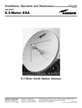
1.6.4.7.2 Figure 1-3 is a schematic diagram that includes both the normal polarizer (8A2A1) and the
passive polarizer (8A2A2), together with the interconnection provided by cables CA1 and CA2. The
circuit configuration is shown for circular polarization. The circular select signal (220 Volts AC)
applied at 8A2A1-.11-L and 8A2A2-J1-L has already driven both motors to the point at which the
switch cam removes power through switches 8A2A1-S4 and 8A2A2-S4. At the same time, status
ground (SG) signal at 8A2A1-J1-E and 8A2A2-J1-E is applied through switches 8A2A1-S2 and
8A2A2-S2 respectively to produce the Circular Status for Low-beam (CSL - for normal polarizer at
8A2AI-Jl-H) and the Circular Status for High-beam (CSH - for the passive polarizer at 8A2A2-J1-
H). At this time, the vanes are inserted at maximum depth in the square waveguide section and
operation is in the circular polarization mode as indicated at the system control panels.
1.6.4.7.3 If a linear select signal (220 Volts AC) is now applied at the polarizers both motors will run
once more and drive to the linear positions of the cams. When each polarizer reaches its preset
position, the switch cam will operate S3 to remove power from the motor and Si to complete the
readback circuit. Thus,
a. motor power will be removed from parallel-connected motor circuits;
b. status ground (SG) signal at 8A2A1-J1-E and 8A2A2-J1-E is applied through switches
8A2A1-S1 and 8A2A2-S1 respectively to produce the Linear Status for Lowbeam (LSL - for
normal polarization at 8A2A1-.11-F) and the Linear Status for Highbeam (LSH - for the
passive polarizer at 8A2A2-J1-F);
c. vanes will be inserted at minimum depth in the square waveguide section;
d. operation will be in linear polarization mode, as indicated at the system control panels. A
circular select signal applied now at 8A2A1-.11-L will cause the motor to drive once more to
the circuit configuration shown in the schematic diagram.
1.6.4.7.4 A capacitor connected across the ac input for each motor provides phase shift for the motor
winding. Capacitor C2 and back-to-back zener diodes that are connected across the motor
windings reduce the generation of transient spikes when the motors are switched off.

17
Figure 1-1 Typical Pattern, Azimuth

18
Figure 1-2 Typical Pattern, Elevation

19
Figure 1-3 Polarizer Schematic

02/08/2016 SDR-ASR11-052
TI 6310.59
20
*
*
/