Page is loading ...

LT-2067 Rev 0
November 2013
RB-MD-1011 Replacement Power Supply Board for FX-3500 Fire Alarm Control Panel
The RB-MD-1011 kit comes with all the parts needed to replace a damaged MD-1011 Power Supply Board on an FX-
3500 Fire Alarm Control Panel.
Parts List
• Qty 1 ... MD-1011 Power Supply Board
• Qty 4 ... #6-32 0.25” screws
Installing the MD-1011 Power Supply Board
1. Disconnect the + and - wires from the BATTERY terminals on the MD-1011(refer to Figure 1 for locations of
connectors and terminals)
.
2. Disconnect the AC power going to the FX-3500 panel.
3. Perform the following steps (refer to Figure 1 for locations of connectors and terminals):
• Disconnect the ribbon cable from P2 on the MD-1011.
• Disconnect the MD-579 power harness from P4 on the MD-1011.
• Disconnect the + and - wires from the BRIDGE terminals on the MD-1011.
• If there is a harness connected to TS1 on the MD-1011, disconnect it.
4. Remove the four screws securing the MD-1011 to the back plate.
5. Remove the damaged MD-1011 and replace it with the new MD-1011.
6. Secure the new board with either the four screws provided or the screws you removed in step 4.
NOTE: Ensure that you secure the ground wire to the upper right corner of the board (see Figure 1).
7. Make the following connections:
• Connect the ribbon cable to P2 on the MD-1011.
• Connect the MD-579 power harness to P4 on the MD-1011.
• Connect the red wire from the + connector on the bridge rectifier to the + BRIDGE terminal on the MD-1011.
NOTE: The + connector on the bridge rectifier is in a different orientation with respect to the other connec-
tors. Specifically, the + connector is perpendicular to the other three connectors.
• Connect the black wire from the - connector on the bridge rectifier to the - BRIDGE terminal on the
MD-1011.
• If there was a harness connected to TS1 on the MD-1011, connect it.
8. Connect the AC power to the FX-3500 panel.
9. Connect the + and - wires from the batteries to the + and - BATTERY terminals on the MD-1011.
NOTE: This is a replacement module for a damaged board. Battery calculations do not have to be updated.

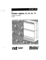
Figure 1: Location of connectors and terminals on the MD-1011 Power Supply board.
MD-1011
#6-32 x .25
SCREWS (X4)
TO BATTERIES
RIBBON CABLE
MD-579
+
−
+
+
−
TS1
BATTERY
−
BRIDGE
P2
P4
MD-1011
GROUND WIRE
/