Lincoln Electric KH513 Installation guide
- Category
- Welding System
- Type
- Installation guide

Aluminum GMAW
Welding Guide

2
www.lincolnelectric.com
Aluminum
For superior welding performance, turn to SuperGlaze
®
aluminum MIG
wire from Lincoln Electric. SuperGlaze
®
prevents the problems usually
associated with aluminum wire feeding such as birdnesting, tangling
and burnback to provide a stable arc, great feedability and exceptional
control –– every time you weld! The keys are SuperGlaze
®
’s smooth
surface finish and consistent chemical composition. What this means
for you is quality wire that produces a quality weld.
Let Us Put Our Experience to Work for You
As a major supplier of welding wire, Lincoln Electric is the leader in
MIG wire manufacturing technology. We carry that same technology
and expertise to our aluminum MIG wire manufacturing. Our fully
integrated aluminum MIG wire facility uses state-of-the-art equipment
to produce a complete range of aluminum alloys including 4043, 4047,
5183, 5356, 5554 and 5556.
What Makes SuperGlaze
®
Stand Out From the Rest?
Three unique features:
1. A proprietary process which gives SuperGlaze
®
a superior surface
finish for optimum surface integrity.
2. A manufacturing process that precisely controls the alloy chemical
composition to produce consistent physical characteristics.
3. State-of-the-art testing equipment to evaluate the
surface condition and feedability of the wire to ensure
problem-free welding.
What all this means to you is outstanding welding characteristics, spool
to spool, time after time. Lincoln Electric’s aluminum MIG wire coupled
with our advanced MIG welding equipment makes aluminum as easy to
weld as any other material... and makes Lincoln Electric the one source
for all your aluminum welding needs.
Lincoln Electric is the world’s leading
manufacturer of welding equipment
and consumables. Our focus is on
helping companies make their welding
operations more effective, more
efficient, more profitable.
We are dedicated to two equally
important goals: exceptional quality
and exceptional service. Our field
support team –– with hundreds of
field sales engineers and thousands of
knowledgeable and responsive Lincoln
distributors in countries all over the
world –– is the largest in the industry.
Innovative thinking.
A quality, service-first attitude.
Fresh approaches to design,
manufacturing, and packaging.
Worldwide strength.
That’s Lincoln Electric.
About The Lincoln
Electric Company
Lincoln’s SuperGlaze
®
Technology
Important Information on our Website
Consumable AWS Certificates:
www.lincolnelectric.com/LEExtranet/MyLincolnCerts/site/default.aspx
Material Safety Data Sheets (MSDS):
www.lincolnelectric.com/msds
ANSI Z49.1 Safety in Welding and Cutting and Arc Welding
Safety Checklist:
www.lincolnelectric.com/safety
Request E205 Safety Booklet:
www.lincolnusmarketing.com

3
Aluminum
www.lincolnelectric.com
Here’s How Our Process Works:
Controlling Alloys
The process of making aluminum MIG wires is a complex
one, but one in which Lincoln Electric has a clear and
distinct advantage. First, we utilize automated titling furnaces
to efficiently produce the proper aluminum alloys. With
this equipment, we are able to hold tight tolerances in the
composition. The alloy is carefully refined prior to casting to
minimize hydrogen, alkaline metals, and inclusions.
Continuous Casting
Second, we use a continuous casting process specially
configured to high alloy materials. This process keeps the
surface free from imperfections and impurities.
Drawing the Wire
In the last step of the manufacturing process, we use advanced
wire drawing technology to preserve both surface integrity and
internal soundness.
Testing the Wire
To ensure superior quality of welding wire, continuous finished
product inspection is done. Surface quality is evaluated along
with feedability and welding performance. This guarantees every
spool of wire is problem-free.
Welding Performance
Most aluminum MIG welding problems are caused by poor
feeding. Since aluminum is relatively soft, it is important that
the wire surface be as smooth as possible for best feedability.
SuperGlaze
®
products provide easier feeding than competitive
products because they have fewer surface imperfections as
shown at the right.
SuperGlaze
®
wire also feeds with less force than typical
competitive products as the feedability test graph shows.
What this means is better control of the weld puddle for the
operator. It also means longer gun liner and contact tip life as
burnbacks do not occur.
With our MIG welding process knowledge, we understand that
welding performance is one of the most important criteria used
when selecting a wire. Aluminum MIG wire tends to produce
a welding arc that is less stable than other materials because
aluminum conducts electricity better. Small changes in wire
diameter, wire feed speed, and current produce dramatic
changes in weld bead profile, arc length and can even cause
equipment downtime due to wire burnback and fusing to
tip. Our continuous evaluation of finished product ensures
consistency in manufacturing. You can count on Lincoln Electric
aluminum MIG wire for superior arc stability, weld appearance,
integrity and productivity.
The SuperGlaze
®
Advantage
5356 Wire Surfaces Magnified 60x
Typical Competitive
Product
SuperGlaze
®
“Best in Class”
Excellent
Time
Poor
Wire Jams and Stops Feeding
Feedability
Lincoln Electric
SuperGlaze
®
Product
Typical
Competitive
Product
Typical
Competitive
Product

4
www.lincolnelectric.com
Aluminum
Contents Page
Effects of Alloying Elements ................................................................. 5-9
Introduction .......................................................................... 5
Welding Aluminum vs. Welding Steel ...................................................... 5
Metallurgy ..........................................................................5-7
Aluminum Alloys .................................................................. 6
Wrought Alloys ................................................................6
Cast Alloys .................................................................. 6
Alloying Elements ..................................................................... 6-7
Temper Designations .................................................................. 7-8
Effects of Welding on Mechanical Properties of Aluminum Alloys .................................... 9
Nonheat-treatable Alloys ................................................................ 9
Heat-treatable Alloys ................................................................... 9
Filler Metal Selection ..................................................................... 10-12
Aluminum Filler Alloys ............................................................... 10-11
Aluminum Filler Metal Guide ............................................................. 12
Welding Preparation ..................................................................... 13-14
Storage of Aluminum and Aluminum Wire Prior to Welding ................................... 13
Welding Preparation ................................................................... 13
Pre-weld Cleaning ................................................................... 13-14
GMAW of Aluminum Alloys ................................................................ 15-18
Properties of Aluminum ................................................................ 15
Modes of Metal Transfer ................................................................ 15
GMAW Power Supplies .............................................................. 15-16
GMAW-P Power Supplies ............................................................... 16
Wire Drives and Controls ............................................................. 16-17
Push and Push-Pull Type Feeders ................................................. 16-17
Push-Pull GMAW Guns and Spool Guns .............................................. 17
Aluminum Feeding Enhancement ........................................................ 17
Shielding Gas ........................................................................ 18
Welding Techniques ................................................................... 18
Welding Defects — Causes and Cures ....................................................... 19-20
Solving Problems in Qualifying Weld Procedures ............................................ 21
Meeting Tensile Test Requirements ................................................ 21-22
Meeting Bend Test Requirements ................................................. 21-22
General Welding Guidelines ............................................................... 23-26
Typical Melting Rates .................................................................. 23
Welding Current vs. Wire Feed Speed ..................................................... 23
Welding Joint Design and Welding Guidelines for Groove Welding ........................... 24-25
Welding Guidelines for Fillet and Lap Welding .............................................. 26
Welding Safety ......................................................................... 27-30

5
Aluminum
www.lincolnelectric.com
Effects of Alloying Elements
Introduction
The use of aluminum as a structural material is fairly recent.
In fact, when the Washington Monument was completed in
December, 1884, it was capped with a 100-ounce pyramid
of pure aluminum, because aluminum was considered to be
a precious metal at that time. The problem that impeded the
use of aluminum is that it is a reactive metal. It is never found in
its elemental state in nature, but is always tightly bound with
oxygen as aluminum oxide, Al
2
O
3
. Although aluminum oxide,
found as bauxite ore, is plentiful, no direct reduction method,
such as they used to make steel, has ever been found to produce
aluminum from bauxite.
It was only after the American Charles M. Hall and the
Frenchman Paul Heroult almost simultaneously, but
independently, discovered electrolytic processes for
obtaining pure aluminum from aluminum oxide (in 1886) that
aluminum became available in commercial quantities. These
processes, with some modifications, are still used today. In
large part, it is the extremely large amount of electrical power
required to produce aluminum that accounts for its higher cost
relative to steel.
Since that time, aluminum has found wide use in numerous
applications:
• It conducts electricity and heat almost as well as copper.
• It is widely used in electrical bus bars and other conductors,
heat exchangers of all kinds, and cookware.
• It does not become brittle with decreasing temperature,
but does become stronger, so it has found wide application
in cryogenic equipment at temperatures as low as
–452°F (-269°C).
• It is very corrosion resistant in most environments, so it has
found wide applications in marine and chemical environments.
The characteristics of aluminum alloys which make them
attractive as structural materials are their light weight (one third
the weight of steel for equal volumes) and their relatively high
strength (equal in many cases to that of construction steel
grades). This combination has resulted in increased use of
aluminum alloys in applications such as passenger automobiles,
trucks, over-the-road trailers, and railroad cars. Additionally, the
structure of most aircraft is fabricated mainly from aluminum
alloys, although in these applications, pieces are most often
joined by riveting.
Welding Aluminum vs. Welding Steel
Most welders start out by learning how to weld steel. Some
later move over to welding aluminum. Most welding equipment
is designed to weld steel, with welding of aluminum alloys often
being an afterthought, although this is changing. Very often
we approach welding of aluminum as if it was just shiny steel.
However, there are differences between steel and aluminum
that usually make this approach doomed to failure.
The balance of this guide will discuss these differences
and how to overcome them. They can all be summed up in
three statements:
I. If you take enough care almost all steels are weldable.
There are some aluminum alloys that just are not arc weldable.
Fabricators fall into this trap regularly. We’ll discuss the
weldability of the various alloy families in detail. At this point, let’s
just say that many aluminum alloys, and especially the stronger
ones, are not weldable.
2. All steels are heat-treatable. Some aluminum alloys are
heat-treatable, but some are not.
Even for the heat-treatable aluminum alloys, the heat treatments
are totally different from those used for steel. In fact, if you heat
up some alloys and quench them, they will become softer, not
harder. Be aware of the differences and act accordingly.
3. When welding steels, you can almost always make a weld
that is as strong as the parent material. In aluminum alloys,
the weld will rarely be as strong as the parent material.
This is usually true for welds in both heat treatable and
nonheat- treatable alloys. The strength difference between
the weld or heat affected zone (HAZ) and the parent material
is often significant, often 30% or more.
Metallurgy
To understand aluminum, we must first understand some
basics about aluminum metallurgy. Aluminum can be alloyed
with a number of different elements, both primary and
secondary, to provide improved strength, corrosion resistance,
and general weldability.
The primary elements that alloy with aluminum are copper,
silicon, manganese, magnesium and zinc. It is important to
note that aluminum alloys fall into two classes: heat-treatable
or nonheat-treatable.
Heat-treatable alloys are those that are heat-treated to increase
their mechanical properties. To heat treat an alloy means heating
it at a high temperature, putting the alloying elements into solid
solution and then cooling it at a rate which will produce a super
saturated solution. The next step in the process is to maintain
it at a lower temperature long enough to allow a controlled
amount of precipitation of the alloying elements.
With the nonheat-treatable alloys it is possible to increase
strength only through cold working or strain hardening. To
do this, a mechanical deformation must occur in the metal
structure, resulting in increased resistance to strain, producing
higher strength and lower ductility.

6
www.lincolnelectric.com
Aluminum
Alloying Elements
Pure Aluminum (1XXX series) Contains no alloying elements,
and is not heat-treatable. It is used primarily in chemical tanks
and pipe because of its superior corrosion resistance. This series
is also used in electrical bus conductors because of its excellent
electrical conductivity. It is welded easily with 1100 and 4043
filler wires.
Copper (2XXX series) Provides high strength to aluminum.
This series is heat-treatable and mainly used in aircraft parts,
rivets and screw products. Most 2XXX series alloys are
considered poor for arc welding because of their sensitivity
to hot cracking. Most of these alloys should not be welded,
however, alloys 2014, 2219 and 2519 are easily welded with
4043 or 2319 filler wire. These three alloys are widely used in
welded fabrication.
Manganese (3XXX series) Yields a nonheat-treatable series
used for general-purpose fabrication and build-up. Moderate
in strength, the 3XXX series is used for forming applications
including utility and van trailer sheet. It is improved through strain
hardening to provide good ductility and improved corrosion
properties. Typically welded with 4043 or 5356 filler wire, the
3XXX series is excellent for welding and not prone to hot cracking.
Its moderate strengths prevent this series from being used in
structural applications.
Silicon (4XXX series) Silicon reduces the melting point of the
aluminum and improves fluidity. Its principle use is as filler metal.
The 4XXX series has good weldability and is considered a
nonheat-treatable alloy. Alloy 4047 is often used in the
automotive industry as it is very fluid and good for brazing
and welding.
Magnesium (5XXX series) When added to aluminum,
magnesium has excellent weldability, good structural strength
and is not prone to hot cracking. In fact, the 5XXX series has the
highest strength of the nonheat-treatable aluminum alloys. It is
used for chemical storage tanks and pressure vessels as well as
structural applications, railway cars, dump trucks and bridges
because of its corrosion resistance.
Aluminum Alloys
Much in the same manner that the American Iron and Steel
Institute (AISI) registers steel chemistries and grades, the
Aluminum Association (AA) registers alloy designations,
chemistries, and mechanical properties for aluminum alloys.
However, the alloy designation system is totally different than
that used for steels. Additionally, different designation systems
are used for wrought and cast alloys.
Wrought Alloys
Wrought alloy designations use a four digit number, plus a
temper designation, discussed later. Aluminum alloys are
broken up into eight “families” depending on the main alloying
elements. The aluminum alloy families are shown in Table 1,
along with their heat treatability.
For example, if you have a piece of 6061, it’s clear that it is
a wrought alloy (4 digits), it’s heat treatable, and it contains
magnesium and silicon. The second digit of the four shows
whether the alloy is the first such alloy registered, in which
case the second digit will be “0”, as in 5054. Digits other than
“0” indicate that the alloy is a modification of a registered alloy.
5154 would be the first modification of 5054. Alloy 5754 is the
seventh modification. The last two digits are assigned arbitrarily
by the Aluminum Association when the alloy is registered. Note
there is no indication of alloy or weld strength given by the
material designation.
Alloy Heat
Family Main Alloying Elements Treatable
1XXX Pure Aluminum No
2XXX Copper (sometimes with magnesium) Yes
3XXX Manganese (sometimes with magnesium) No
4XXX Silicon No
5XXX Magnesium No
6XXX Magnesium plus silicon Yes
7XXX Zinc (sometimes with magnesium and copper) Yes
8XXX All others
Normally
Yes
NOTE: The designation 2XXX, etc. is an industry standard abbreviation
used to mean “all the alloys in the 2000 series”.
Table 1: Wrought Alloy Destinations
Alloy Heat
Family Main Alloying Elements Treatable
1XX.X Pure Aluminum No
2XX.X Copper Yes
3XX.X Silicon plus magnesium Yes
4XX.X Silicon Yes
5XX.X Magnesium No
6XX.X Not Used NA
7XX.X Zinc Yes
8XX.X Tin No
9XX.X Other
Table 2: Cast Alloy Destinations
Cast Alloys
The designation system for cast alloys are classified into
families as shown in Table 2. The specific families are
somewhat different from the designations for wrought alloys
and the designations have only three digits followed by a
decimal point and one more digit. For these alloys, the first
digit shows the alloy family. The next two digits are arbitrarily
assigned. Alloy modifications are shown by a letter prefix,
so 356 is the original version of an alloy and A356 is the first
modification, B356 is the second modification, etc. The number
following the decimal point designates whether the alloy is
produced as a casting of final form or is produced as an ingot
for re-melting.

7
Aluminum
www.lincolnelectric.com
Silicon and Magnesium (6XXX series) This medium strength,
heat-treatable series, is primarily used in automotive, pipe,
railings, and structural extrusion applications. The 6XXX series is
prone to hot cracking, but this problem can be overcome by the
correct choice of joint and filler metal. Can be welded with either
5XXX or 4XXX series without cracking — adequate dilution of the
base alloys with selected filler wire is essential. A 4043 filler wire
is the most common for use with this series. 6XXX alloys should
never be welded autogenously, they will crack.
Zinc (7XXX series) Zinc added to aluminum with magnesium
and copper produces the highest strength heat-treatable
aluminum alloy. It is primarily used in the aircraft industry.
The weldability of the 7XXX series is compromised in
higher copper grades, as many of these grades are crack
sensitive (due to wide melting ranges and low solidus melting
temperatures). Grades 7005 and 7039 are weldable
with 5XXX filler wires. They are widely used for bicycle
frames and other extruded applications.
Other (8XXX series) Other elements that are alloyed with
aluminum (i.e. lithium) all fall under this series. Most of these
alloys are not commonly welded, though they offer very good
rigidity and are principally used in the aerospace industry.
Filler wire selection for these heat-treatable alloys include the
4XXX series.
In addition to the primary aluminum alloying elements, there
are a number of secondary elements, which include chromium,
iron, zirconium, vanadium, bismuth, nickel and titanium. These
elements combine with aluminum to provide improved corrosion
Temper Designations
The information above allows an aluminum alloy to be recognized
by its chemistry, but not by the heat treatment or mechanical
properties. To show these properties, temper designations are
assigned. The complete designation of an alloy might be 6061-T6
or 5083–H114. Most of these designations are different for
heat-treatable and nonheat-treatable alloys; however, two
common designations apply to all alloys:
• “O” Temper (not zero). When an alloy is given this designation,
the supplier has annealed the alloy, typically at 650-750°F
(343-300°C), and it is as soft as possible.
• “F” Temper. When an alloy is supplied in this temper it
is supplied “as fabricated”. This means the supplier is
guaranteeing that the chemistry of the material meets the
chemical requirements for the specified alloy, but there are no
claims regarding the mechanical properties of the alloy. This
temper is often specified by fabricators who subsequently
forge or form the supplied material and establish mechanical
properties by heat treatment after forming.
To discuss the remainder of the temper designations, we need
to discuss the heat-treatable and nonheat-treatable alloys.
Nonheat-Treatable Alloys — Strain-Hardened Designations
These alloys cannot be strengthened by heat treatment.
However, they can be strengthened by cold working, also
called strain hardening. If an aluminum alloy is deformed at
elevated temperatures, [600°F (315°C) or higher], little or no
strengthening takes place. However, if the alloy is deformed at
lower temperatures, it will gain strength. In general:
• The more the alloy is deformed, the stronger it gets. Finally, at
some point, the alloy will have no ductility and will fracture.
• The higher the alloy content, the more it will gain strength by
being deformed.
Both of these phenomena are shown in Figure 1.
Figure 1: Relationship of Yield Strength, Amount of Cold
Work and Alloy Content
The temper designation for strain hardened alloys is usually
made up of two digits as shown in Table 3.
The first digit shows whether the alloy is only strained or whether
it has been partially annealed and/or stabilized. The second digit
shows how much strain hardening has been put into the alloy.
Higher numerical values mean higher strain levels, which means
higher yield and tensile strengths.
First Digit Indicates Basic Operations
H1 — Strain Hardened Only
H2 — Strain Hardened and Partially Annealed
H3 — Strain Hardened and Stabilized
Second Digit Indicates Degree of Strain Hardening
HX2 — Quarter Hard
HX4 — Half Hard
HX6 — Three-Quarters Hard
HX8 — Full Hard
HX9 — Extra Hard
Table 3: “H” Temper Designations
Heat Treatable Alloys
Strain hardened “H” tempers are not used for heat-treatable
alloys. Instead a series of “T” tempers indicating the heat
treatment state are used. A total of (10) tempers exist; “T1”
through “T10”. The commonly seen designations are “T4”
and “T6”. All 10 designations are listed in Table 4 on the
following page.

8
www.lincolnelectric.com
Aluminum
T1 Cooled from an elevated temperature shaping process
and naturally aged to a substantially stable condition.
Applies to products that are not cold worked after cooling
from an elevated temperature shaping process, or in which
the effect of cold work in flattening or straightening may not
be recognized in mechanical property limits.
T2 Cooled from an elevated temperature shaping process,
cold worked and naturally aged to a substantially stable
condition. Applies to products that are cold worked to
improve strength after cooling from an elevated temperature
shaping process, or in which the effect of cold work in flatten-
ing or straightening is recognized in mechanical property limits.
T3 Solution heat-treated
(1)
,
cold worked and naturally aged
to a substantially stable condition. Applies to products that
are not cold worked to improve strength after solution heat
treatment, or in which the effect of cold work in flattening or
straightening is recognized in mechanical property limit.
T4 Solution heat-treated
(1)
and naturally aged to a
substantially stable condition. Applies to products that are
cold worked after solution heat-treatment, or in which the
effect of cold work in flattening or straightening may not be
recognized in mechanical property limits.
T5 Cooled from an elevated temperature shaping process
and then artificially aged. Applies to products that are not
cold worked after cooling from an elevated temperature
shaping process, or in which the effect of cold work in
flattening or straightening may not be recognized in mechanical
property limits.
T6 Solution heat-treated
(1)
and then artificially aged.
Applies to products that are not cold worked after solution
heat-treatment, or in which the effect of cold work in
flattening or straightening may not be recognized in mechanical
property limits.
Aluminum alloys are heat treatable because of a phenomenon
called precipitation hardening. They do not harden by a
martensitic transformation as steel does. In precipitation
hardening, one metal can be dissolved in another in a “solid
solution” and solubility generally increases with temperature.
For example, just as sugar will dissolve in a glass of iced tea
when heated — copper, zinc or combinations of magnesium
and silicon will dissolve in aluminum as it is heated.
When the heat-treatable alloys are heated to approximately
950°F (510°C), and held for a few minutes, all the alloying
elements are taken into a solution in the solid aluminum.
This is termed a “solution heat treatment”. Normally, the alloy
is quenched in water from this point to arrive at the T4
temper. Although the T4 temper is substantially stronger than
the annealed “O” temper, the primary purpose of quenching is
not strengthening. Instead, the quenching serves to keep the
alloy additions in solution at room temperature — if the
aluminum were cooled slowly from the solution treatment, the
alloying additions would re–precipitate and no strengthening
would occur.
Table 4: T1 through T10 Temper Designations
T7 Solution heat-treated
(1)
and overaged/stabilized. Applies
to wrought products that are artificially aged after solution heat
treatment to carry them beyond a point of maximum strength to
provide control of some significant characteristic
(2)
. Applies to
cast products that are artificially aged after solution heat
treatment, to provide dimensional and strength stability.
T8 Solution heat-treated
(1)
, cold worked, and then artificially
aged. Applies to products that are cold worked to improve
strength, or in which the effect of cold work in flattening or
straightening is recognized in mechanical property limits.
T9 Solution heat-treated
(1)
, artificially aged, and then cold
worked. Applies to products that are cold worked to
improve strength.
T10 Cooled from an elevated temperature shaping process,
cold worked, and then artificially aged. Applies to
products that are cold worked to improve strength, or in
which the effect of cold work in flattening or straightening is
recognized in mechanical property limits.
(1)
Solution heat treatment is achieved by heating cast or wrought products
to a suitable temperature, holding at that temperature long enough to
allow constituents to enter into solid solution and cooling rapidly enough
to hold the constituents in solution. Some 6XXX series alloys attain the
same specified mechanical properties whether furnace solution heat
treated or cooled from an elevated temperature shaping process at a
rate rapid enough to hold constituents in solution. In such cases, the
temper designations T3, T4, T6, T7, T8 and T9 are used to apply to
either process and are appropriate designations.
(2)
For this purpose, characteristic is something other than mechanical
properties. The test method and limit used to evaluate material for this
characteristic are specified at the time of the temper registration.
The tensile and yield strengths of the material will increase for
several weeks after the heat treatment and, in some alloys, can
increase significantly. However, once past this initial period, the
alloy is stable indefinitely. The user normally is unaware of this
initial strength increase because the aluminum producer doesn’t
ship the alloy until the strength has stabilized.
The T4 temper, while stable, does not give maximum strength to
the alloy. Most alloys are sold in a maximum strength T6 temper.
To get from T4 to T6 temper, the material is put in a furnace at
a temperature of 325°F to 400°F (163°C to 204°C) and allowed
to age 1 to 5 hours. The dissolved alloying elements will form
submicroscopic pre-precipitates in the material and produce
maximum strength. If this aging heat treatment is carried out at
too high a temperature or for too long, the precipitates will get
too large and a lower strength “overaged” condition will result.
Note: This final aging heat treatment is carried out at 400°F (204°C)
maximum. The welding heat, which can heat the surrounding material to
well over this temperature, can significantly degrade the strength of the
weld heat affected zone (HAZ), which is discussed in more detail on the

9
Aluminum
www.lincolnelectric.com
As before, it is easiest to discuss the effects of welding on the
mechanical properties of aluminum weldments if we discuss
nonheat-treatable alloys and heat-treatable alloys separately.
Nonheat-Treatable Alloys
As was discussed earlier, these alloys can be, and often are,
strengthened by cold working. Cold worked alloys can have
yield and tensile strengths twice those of the annealed “O”
temper alloy. These cold worked alloys can be softened back to
the “O” temper by annealing at 650-700°F (343-371°C). Since
the heat of welding produces temperatures considerably higher
than this at the weld fusion line, the result of welding is that the
heat affected zone (HAZ) of welds in nonheat-treatable alloys
(ie, 1XXX, 3XXX, 4XXX, and 5XXX alloys) becomes annealed.
Therefore, the strength of the weld joint is always equal to the
strength of the “O” temper annealed base material, regardless of
what the starting temper of the parent material was. If you weld
“O” temper material, the weld will be as strong as the starting
parent material. If you weld any material that is strain hardened
(ie, cold worked), the weld will be weaker than the starting
material, perhaps significantly weaker.
The HAZ can never become softer then the “O” temper, so that
excess welding heat input will not make the HAZ softer. It can,
however, make the HAZ wider. Normally, this will not further
reduce the strength of the welded joint, although other problems
can arise due to excessive heat input.
From a practical standpoint, there is no way to regain the
strength lost during welding. If the weld is cold worked, it will
begin to work harden again. However, this is not usually a
practical industrial solution, because, in most cases, the weld
will not be as strong as the starting cold worked material.
Heat-Treatable Alloys
There is no blanket statement that can be made about the
welded strength of heat-treatable alloys. As previously
stated, the weld will generally be weaker than the parent
material. However, the welded properties will strongly depend
on the temper of the material before welding and also on
heat treatments performed after welding. Figure 2 shows a
micro-hardness trace across a weld, starting at the center of the
weld. The graph actually shows four curves representing what
happens to material in the T4 and T6 tempers in the as-welded
(AW) and postweld heat-treated (PWA) conditions. The following
can be noted:
1) The HAZ is about 1/2 in. (12.7 mm) wide. The actual width
of the HAZ will depend on a number of things, including the
welding process used and the thickness of the material. HAZ
widths of 1 in. (25.4 mm) are not uncommon in thin materials.
2) The hardness and strength of the weldment is typically lowest
in the HAZ. Because of this, strength of the welding filler alloy is
not a primary concern when making butt welds. A weld will most
often fail in the HAZ.
3) Unlike nonheat-treatable alloys, the hardness (and therefore
strength) in the HAZ is not always the same. It depends on
the material temper prior to welding and whether the weld is
post-weld aged.
a) The weakest HAZ occurs when the material is welded in the
T6 temper and used as–welded.
b) The HAZ, and therefore the weldment, will actually be
slightly stronger if the material is used in the T4 temper and
used as–welded.
c) If the weldment in either T4 or T6 material is post-weld aged,
the strength of the HAZ can increase significantly. The exact
postweld heat treatment varies with the alloy, but is usually an
aging at around 400°F (204°C) for about one hour.
The fabricator has some options that he doesn’t have when
fabricating the nonheat-treatable alloys in terms of recovering
some of the strength lost during welding. For instance, since the
6XXX alloys also bend easier and around a smaller radius in the
T4 temper than in the T6 temper, these alloys can be bought
in the T4 temper, formed easily, welded, and then aged. The
resulting mechanical properties will be significantly higher than if
the material was purchased in the T6 temper.
Finally, if the right filler alloy is chosen, the finished weldment
can be completely heat-treated and the T6 properties restored.
This requires a re-solution heat treatment, quench, and re-aging.
This is often practical for small structures, but not for large ones.
For example, aluminum bicycle frames are often fabricated in
this way.
The HAZ of welds in heat-treatable alloys is significantly
different than those in nonheat-treatable alloys. The strength
of the HAZ in heat-treatable alloys can be made considerably
wider and weaker if excessive heat input is used. Therefore, it
is very important not to use excessive preheats [200°F (93°C)
maximum is recommended], to carefully monitor interpass
temperatures [250°F (121°C) maximum is recommended], and
to avoid practices such as wide weave passes which will result
in excessive heat input.
Figure 2: Hardness vs. Distance for 6061-T4 and -T6 in the
as-welded and post-weld aged conditions
Effects of Welding on Mechanical Properties of Aluminum Alloys

10
www.lincolnelectric.com
Aluminum
AWS A5.10-99
ASME SFA-5.10
Classification
%Mn %Si %Fe %Mg %Cr %Cu %Ti %Zn %Be %Others
(1)
%Al
ER1100 & 0.05 — — — — 0.05-0.20 — 0.10 0.05 99.0
Alloy 1050
ER2319 0.20-0.40 0.20 0.30 0.02 — 5.8-6.8 0.10-0.20 0.10 (2) 0.05
(3)
Balance
ER4043 0.05 4.5-6.0 0.8 0.05 — 0.30 0.20 0.10 (2) 0.05 Balance
ER4047 0.15 11.0-13.0 0.8 0.10 — 0.30 — 0.20 (2) 0.05 Balance
Alloy 5052 0.10 0.25 0.40 2.2-2.8 0.15-0.35 0.10 — 0.10 (2) 0.05 Balance
Alloy 5056 0.05-0.20 0.30 0.40 4.5-5.6 0.05-0.20 0.10 — 0.10 (2) 0.05 Balance
Alloy 5154 0.10 0.25 0.40 3.1-3.9 0.15-0.35 0.10 0.20 0.20 (2) 0.05 Balance
ER5183 0.50-1.0 0.40 0.40 4.3-5.2 0.05-0.25 0.10 0.15 0.25 (2) 0.05 Balance
ER5356 0.05-0.20 0.25 0.40 4.5-5.5 0.05-0.20 0.10 0.06-0.20 0.10 (2) 0.05 Balance
ER5554 0.50-1.0 0.25 0.40 2.4-3.0 0.05-0.20 0.10 0.05-0.20 0.25 (2) 0.05 Balance
ER5556 0.50-1.0 0.25 0.40 4.7-5.5 0.05-0.20 0.10 0.05-0.20 0.25 (2) 0.05 Balance
ER5654 0.01 — — 3.1-3.9 0.15-0.35 0.05 0.05-0.15 0.20 (2) 0.05 Balance
Filler Metal Selection
Aluminum Filler Alloys
Most common aluminum filler alloys fall into the 4XXX and 5XXX
families, with a few coming from the 1XXX, 2XXX, and the
casting alloys. The chemical composition of the common
aluminum filler alloys is shown in Table 5, below.
There are a number of characteristics which determine the best
filler metal choice for a given base material, or combination of
base materials. Among these are:
• Freedom from hot cracking
• Weld metal ductility
• Weld metal corrosion resistance
• Weld metal shear strength in fillet and lap joints
• Ease of welding (i.e., weldability)
• Filler wire feedability
• Weld color match with parent metal for applications requiring
postweld anodizing
There are a number of filler metal selection charts which
have taken these factors into account and give good overall
recommendations for filler metal selection. A composite of these
charts covering most alloy combinations are shown in Table 8
on page 12.
In general, filler alloy recommendations for the various alloy
families can be summarized as follows:
1XXX alloys — These alloys are usually used for their
electrical conductivity and/or corrosion resistance. Their
sensitivity to hot cracking is very low. They are usually welded
using 1100 or 1188 fillers, but matching filler metals are also
available for specialized alloys such as 1350. If electrical
conductivity of the joint is not of primary importance, 4043
may be used.
2XXX alloys — Many alloys in this series are not arc weldable.
Those that are include 2219, 2014, 2519, 2008, and 2036. Alloy
2319 is a matching filler alloy for 2219 and 2519 and can also
be used on the other weldable alloys. Alloys 4043 and 4145,
which contain copper, can also be used. Alloy 5XXX
fillers should not be used to weld 2XXX parent materials,
because cracking will result.
3XXX alloys — These moderate strength aluminum–manganese
alloys are relatively crack resistant and can be welded easily
using either 4043 or 5356.
4XXX alloys — These alloys are usually found as welding or
brazing fillers. In the rare event they are encountered as parent
materials, 4047 is usually the best choice as a filler metal.
Table 5: Wire Chemical Composition for Common Aluminum Wires
(1) Total of “others” shall not exceed 0.15%.
(2) Beryllium shall not exceed 0.0003%.
(3) Vanadium content shall be 0.05 - 0.15% and Zirconium content shall be 0.10 - 0.25%.
NOTE: Single values are maximum, except aluminum.

11
Aluminum
www.lincolnelectric.com
SuperGlaze
®
Aluminum GMAW Wire
5XXX alloys — These higher strength aluminum–magnesium
alloys are the most common structural aluminum sheet and
plate alloys. The general rule, except for the alloy 5052, is
to choose a 5XXX filler metal with slightly higher magnesium
content than the parent material being welded. For all alloys
except 5052, 5XXX alloys should not be welded using 4XXX
filler alloys. The high Mg content of the parent material, when
combined with the high Si content of the 4XXX fillers, will result
in a high level of Mg
2
Si — a brittle intermetallic compound which
will cause the weld to have poor ductility and toughness. In
choosing filler alloys for 5XXX alloys, there are several specific
recommendations as follows:
5052 — This alloy has just the right amount of Mg content to
exhibit a relatively high crack sensitivity. If it is welded with
5052 filler alloy, it will often crack. To avoid the tendency to
crack, 5052 is usually welded with a filler alloy of much higher
Mg content, such as 5356. The resulting weld metal, which is
an alloy of the 5356 and 5052, has a Mg content high
enough to be crack resistant. Additionally, the Mg content of
5052 is low enough so that it can be successfully welded
using 4043.
High temperature applications — Al-Mg alloys with Mg
content over 3% are unsuitable for service temperatures over
150°F (65°C) because they are susceptible to stress
corrosion cracking at higher temperatures. This is true for
filler alloys as well and should be taken into account in
selecting filler alloys
5454 — This alloy is a lower Mg alloy specifically developed
to be immune to the stress corrosion cracking noted above.
Filler alloy 5554 is designed as a matching filler alloy for 5454
and should be used whenever possible.
5083 and 5456 — These high Mg, high strength alloys
can be successfully welded using 5356. However, most
structural Codes require that welds in these alloys have a
minimum ultimate tensile strength of 40 ksi (276 MPa).
When welded using 5356, welds in these alloys often will
not meet this requirement. For this reason, 5183 or 5556
are recommended for these alloys.
6XXX alloys — These Al-Mg-Si alloys are primarily used for
extrusion alloys, although they can also often be found as sheet
and plate. The chemistry of these alloys makes them very
sensitive to hot short cracking. Autogenous welds (i.e., welds
made without adding filler metal) will almost always crack. This is
why 6061 filler metal does not exist. If it did, welds made using
it would crack. Yet, these alloys are readily weldable using either
4043 or 5356 filler metal. Since the chemistry of 4043, Al with
5% Si, or 5356, Al with 5% Mg, is so different than that of 6061,
when either is mixed with 6061, the result is a weld with a crack
resistant chemistry.
The decision whether to use 4043 or 5356 depends on a
number of factors summarized in Table 7. This table compares
these two common filler metals and shows the advantages and
disadvantages of each.
As shown in Table 7, 4043 is easier for the welder to use, it
flows better, and is more crack resistant. Filler metal 5356 feeds
better and gives welds that are stronger, especially in lap welds
and fillet welds, and are more ductile. While 5356 should be
used to weld the 6XXX alloys to any of the 5XXX alloys, 4043
should be used to weld the 6XXX alloys to the common 3XX.X
casting alloys.
ER4043 ER5356
Smooth Bead, Good Wetting Black Smut, Distinct Ripples
Low Column Strength Best Feedability
Higher Penetration Lower Penetration
Lower Ductility Higher Ductility
Lower Tensile Higher Tensile
Less Prone to Porosity More Prone to Porosity
Anodizes a Dark Grey Anodizes with Good Color Match
Much Lower Shear Strength Higher Shear Strength
Lower Cracking Sensitivity Higher Cracking Sensitivity
Lower Melting Point Higher Melting Point
Narrower Melting Range Wider Melting Range
Table 7: Comparison of Filler Metals 4043 and 5356
Note: 5356 should be used for applications that will be subsequently
anodized. 5356 will anodize to a color very similar to the parent material.
4043 will turn dark grey on anodizing. Since the 6XXX parent materials
anodize to a clear color, a 4043 weld is very visible and not desirable.
7XXX alloys — Although most of these alloys are not
arc-weldable, 7005, 7003, and 7039, display good
weldability. These alloys should be welded using 5356.
Aluminum
AWS Lincoln Electric
Classification Product Name
ER4043 SuperGlaze
®
4043
ER4047 SuperGlaze
®
4047
ER5183 SuperGlaze
®
5183
ER5356 SuperGlaze
®
5356
ER5554 SuperGlaze
®
5554
ER5556 SuperGlaze
®
5556
Table 6: Aluminum Product Selection Guide
Request publication C1.10 for more information on Lincoln Electric
SuperGlaze
®
premium aluminum GMAW wire.

12
www.lincolnelectric.com
Aluminum
1060, 1100, 5086, 6005, 6061 356.0, A356.0, 357.0,
3003, 2219, 3004, 5005, 5052, 5083, 514.0, 5154, Alclad 6061, 354.0 A357.0, 359.0,
Base Metal to Base Metal Alclad 3003 A201.0 Alclad 3004 5050 5652 5456 535.0 5254 5454 6063, 6351 7005 C355.0 443.0 A444.0
356.0, A356.0, 357.0,
A357.0, 359.0, 443.0, 4043 4145 4043 4043 4043 5356 5356 4043 4043 4043 4043 4145 4043
A444.0
354.0, C355.0 4145 4145 4145 4145 4043 NR NR NR 4043 4145 4145 4145
7005 5356 4145 5356 5356 5356 5556 5356 5356 5356 5356 5356
6005, 6061, Alclad 6061, 4043 4145 5356 4043, 5356, 5356 5356 5356 5356 4043,
6063, 6351 5356 4043 5356
5454 4043 4043 5356 5356 5356 5356 5356 5356 5554
5154, 5254 4043 NR 5356 5356 5356 5356 5356 5356
5086, 514.0, 535.0 5356 NR 5356 5356 5356 5356 5356
5083, 5456 5356 NR 5356 5356 5356 5556,
5183
5052, 5653 4043 4043 4043 4043, 5356
5356
5005, 5050 4043 4145 4043 4043,
5356
3004, Alclad 3004 4043 4145 4043
2219, A201.0 4145 2319
1060, 1100, 3003, 1100
Alclad 3003
Notes:
1) The filler alloy shown is the best choice for most structural applications. Where two filler alloys are shown, either are acceptable.
2) Whenever 4043 filler alloy is shown, 4047 is an acceptable alternate.
3) Whenever 5356 filler alloy is shown, 5556 or 5183 are acceptable alternates.
4) Al-Mg alloys containing more than 3% Mg should not be used in applications where long term exposures above 150°F (65°C) are encountered.
5) There are applications where specific requirements make the selection of filler alloys other than those shown above necessary.
Table 8: Aluminum Alloy Filler Metals for Structural Welding of Various Base Aluminum Alloys

13
Aluminum
www.lincolnelectric.com
Welding Preparation
Preparation for welding includes storage and handling of
aluminum prior to welding, methods for making the weld
preparation, and methods for cleaning prior to welding. While
not strictly “welding preparation”, methods for backgouging
and interpass cleaning will be included in this section.
Storage of Aluminum and Aluminum Wire
Prior to Welding
Improper storage of aluminum and aluminum wire prior to
welding makes preparation for welding much more costly at
best. At worst, it can result in welds of inadequate quality.
It is well known that all aluminum alloys form a thin oxide coating
immediately upon exposure to air. This coating is extremely
thin, approximately 100–150 Angstroms (one millionth of a
centimeter) thick. Because it is so thin, it is transparent and not
visible to the naked eye. When stored at ambient temperatures
and relative humidity levels of 70% or below, the oxide thickness
increases extremely slowly. It is safe to say that aluminum and
aluminum wires stored under these conditions will be usable for
a couple of years. Plus, the reverse polarity arc tends to strip off
the oxides. Therefore, if aluminum is stored in a dry area, oxide
removal prior to welding will be very easy or unnecessary.
However, if aluminum is subjected to temperatures above
200°F (93°C) and/or very high humidity levels, the oxide layer
thickness can grow rapidly. Because of this, the following
guidelines are suggested:
• Aluminum plate which has ever become wet should be
scrapped. Boxes of wire where the cardboard box has
become wet on the inside should be discarded.
• Aluminum should never be stored outside.
• Wire should be stored in the original box and any plastic
interior bag it came in.
• It is helpful to store wire in a closed cabinet which is heated
to approximately 20°F (-6°C) above the ambient temperature
to reduce relative humidity. This can be done simply by
mounting an electrical fixture with a low wattage bulb inside
the cabinet and letting the bulb burn continuously.
• Wire which will not be used for 2 days or more should be
dismounted from the wire feeder, returned to its original
packaging, and stored properly.
Aluminum wire which is stored in accordance with the above
recommendations will be usable with no deterioration in
performance for at least 2 years. Wire older than this should
be discarded.
Oxides on aluminum plate can be removed by power wire
brushing, sanding, grinding, or chemical etching, however,
proper storage will prevent the formation of oxides. Aluminum
should be stored indoors in a dry environment. If stored
outside, it should be securely covered to keep it dry. Under
no circumstances should it be stored uncovered with one plate
laying flat on top of another. This will allow water to “wick” in
between the plates from the edges. If this happens, thick
hydrated oxide will form very quickly on the plate surfaces,
making it very difficult to pry the two plates apart.
Welding Preparation
Even the hardest aluminum alloy is much softer than a high
speed steel or carbide cutting tool. While specialized tools are
available to cut aluminum, aluminum is easily cut using circular
saws, radial arm saws, etc. End preparations can be put on pipe
or tube using woodworking routers. The general rule is “if it will
cut wood, it will cut aluminum”.
While aluminum can’t be cut using oxyfuel cutting equipment, it
can be easily cut using plasma cutting equipment. Thin aluminum,
less than 3/16 in. (4.8 mm) thick, can also be cut by high
powered lasers. However, care must be taken in plasma or laser
cutting of heat-treatable alloys. These alloys are prone to form
micro-cracks which can extend back from the cut edge as
far as 1/8 in. (3.2 mm). Therefore, laser or plasma cut edges in
heat-treatable alloys are usually machined to remove the edge
before welding. Methods of weld preparation are as follows:
Machining
Machining of weld preparations can be performed using a
variety of tools. Milling machines, bed planers, and shapers are
commonly used with carbide cutting tools. It is recommended
that any machining be performed dry, i.e., without any cutting
lubricants. Lubricants are either oil (hydrocarbon) or water-based.
If lubricants are used, the residue must be removed before
welding. If not removed, excessive porosity will result.
Sawing
Both band and circular saws are commonly used to make
weld preparations. Higher blade speeds and coarser teeth are
required than when cutting steel. Recommended blade surface
speeds are 8000 sfpm for circular saws and 5000 sfpm for
band saws. Band saw blades should have no more than 4 teeth
per inch. If circular saws are used, the cut quality can be good
enough so that no further preparation is necessary. Band saws
usually leave a coarse surface which must be sanded or grinded.
Grinding and Sanding
The use of grinding and/or sanding to form weld preparations
has been discouraged in the past, because organic binders in
the disc often left behind organic residues which then caused
weld porosity. However, there are a number of grinding and
sanding discs available today which are specifically formulated
for aluminum. These can give excellent results for forming weld
preparations on aluminum.
Shearing
Shearing is very useful to cut sheets or plates to size. However,
the edge quality is rarely acceptable for welding. It is relatively
rough and has a lot of crevices which can trap oils, greases, etc.
It is recommended that the edge be smoothed by machining,
grinding, or sanding after shearing.

14
www.lincolnelectric.com
Aluminum
Pre-weld Cleaning
Once the weld preparation is formed, it must be cleaned before
the weld joint is fit together. Cleaning consists of removing any
contaminants. These contaminants are as follows:
(1) Oils and Greases
Removal of oils and greases can be performed in one of several
ways. First, wiping with a clean rag saturated with a degreasing
solvent. This method is very effective. However, the use of many
solvents has been severely curtailed in recent times because of
environmental concerns. Second, mild alkaline solutions make
good degreasers. The part to be degreased can be sprayed
with these solutions or dipped into a tank containing them.
Since such cleaners are usually water based, it is important
to thoroughly dry the part after degreasing. Third, many
suppliers sell acid based cleaning solutions for cleaning
aluminum. These are usually effective. However, all are
acidic and some contain hydrofluoric acid, so caution in their
use and disposal is required. Again, since they contain water,
the piece must be thoroughly dried before welding.
Whichever method is used, it is important to degrease the
part to be welded before performing any of the oxide removal
procedures outlined below. Otherwise the oils and greases will
be spread by the oxide removal and will be difficult to remove.
(2) Excess Oxides
Once the oils and greases are removed, oxide removal can
be performed in several ways. The most common is to use a
stainless steel wire brush. The brush should be clean and not
previously used on materials other than aluminum. The brush
should be relatively flexible and should be used with only light
pressure in order to avoid unnecessarily roughening the surface
of the aluminum.
Oxide removal can also be performed by immersing the part
in a strong alkaline solution. However, these solutions are very
corrosive, and can etch the surface of the aluminum, therefore,
extreme care must be used.
In some industries, especially the aerospace industry, final
oxide removal is performed just before the joint is fit together
by mechanically removing the oxide using a steel scraper
(identical to those used in woodworking) or by draw filing. Once
the cleaning is performed, the joint is fit together as soon as
possible. These are very effective methods for oxide removal.
However, they are time consuming, costly, and are primarily
used in industries where the demand for extremely high quality
overrides the additional cost.
Interpass Cleaning
The surface of a weld usually has areas of oxides and weld
“smut” on it. This gray to black colored smut is composed
of aluminum oxide and magnesium oxide. Before depositing
another weld pass, it is recommended that the smut and oxides
be removed, because they can cause lack of fusion defects.
The easiest way to remove these oxides is to use a wire brush,
either manual or power driven. The wire brush should be clean
and used only on aluminum. It should be flexible and used with
light pressure.
Backgouging
When making a double-sided weld, it is necessary to remove
the metal on the back side to sound metal before depositing the
back side weld. If this isn’t done and the backside weld is made
with no preparation, lack of fusion will often result.
The usual geometry for the backgouged seam is a V preparation
with a 60° included angle and a 1/8 in. (3.2 mm) radius at the
base. There are a number of ways to perform this backgouging:
(1) Air Arc or Plasma Arc Gouging
Either of these processes can be used successfully. However,
they rely on the skill and steadiness of the operator to obtain a
uniform backgouge. In addition, they usually require cleaning
up with a grinding disk before welding. This is especially true
of air arc gouging, which leaves carbon deposits in the gouged
groove. If the carbon isn’t removed, porosity on the backside
weld can result.
(2) Grinding
A thin 1/8 in. (3.2 mm) grinding disk on edge can be used for
backgouging. Again, the operator must be skilled in order to
produce a uniform gouge.
(3) Machining
Ideally, the best way to get a uniform backgouge is to mount
the weld in a milling machine and machine the backgouge.
Unfortunately, this usually isn’t practical. However, a number
of manufacturers supply a pneumatically powered circular saw
mounting a 4 in. (102 mm) diameter milling cutter. This milling
cutter is ground to have a tooth form with a 60° V with a 1/8 in.
(3.2 mm) tip radius. The depth of the backgouge is set by
setting the cutting depth of the saw. It is relatively easy to
set up a straightedge to guide the saw along to get a
straight backgouge.
(4) Chipping
Although not used very often, the use of a pneumatic chipping
hammer with the appropriate chisel can be a very effective way
to backgouge. The problem with this method is the extremely
high noise level produced. It is very easy to regulate the cutting
depth to get down to sound metal because it is obvious to the
operator when sound metal is reached. The effectiveness of this
method is very dependent on the geometry of the chisel. The
correct geometry is shown in Figure 3.
Figure 3: Correct Pneumatic Chisel Geometry for
Backgouging Aluminum

15
Aluminum
www.lincolnelectric.com
If available, GMAW-P is able to join thin and thick sections of
aluminum. For those materials that are less than or equal to
0.125 in. (3.2 mm), pulsed spray transfer is the preferred choice.
Pulsed spray transfer is more easily able to join materials less
than 0.125 in. (3.2 mm), and this is due to the fact that the
average current is lower in magnitude for GMAW-P than axial
spray transfer welding current. When compared to axial spray
transfer GMAW-P has the following advantages when used for
welding aluminum:
• Lower heat input – less distortion
• Ability to handle poor fit-up
• Ability to handle thinner materials
• The lower heat input of GMAW-P reduces the size of the
heat affected zone
• Out-of-position welding is greatly enhanced
Power Supplies and Wire Drives
The history of the development of power sources for aluminum
GMAW welding relates to the development of constant current
(CC), or constant voltage (CV) output characteristics. Prior to the
development of CV power sources the use of CC or “drooper”
type power sources were used exclusively for welding aluminum.
Special techniques were required for arc striking and special
variable speed wire drives were developed as a solution for the
unstable arc length associated with constant current.
Constant current power sources provided excellent penetration
uniformity, and they reacted slowly to changing conditions.
The slower dynamic response to changes in arc length were
desirable for welding thicker sections of aluminum with
electrode diameters 3/32 in. (2.4 mm) and larger. The primary
disadvantage of CC power sources is arc starting and the ability
to regulate arc length.
In the late 1950s, when selenium rectifiers were employed
to provide the CV output characteristics, many aluminum
fabricators soon realized there was a problem. The output of
the early CV power sources produced wide welding current
fluctuations due to changes in arc length, and this was com-
pounded by changes in output due to fluctuations in input
power. Because of the higher thermal conductivity of aluminum
the current changes that occurred produced variations in weld
penetration. Incomplete fusion defects often accompanied the
Properties of Aluminum
The engineering use of wrought and cast aluminum base
materials continues to increase, and it does so because of the
basic properties of this unique material. The more prominent
features of aluminum and its alloys are:
• Aluminum is lightweight. It weighs about one third that of
steel. A cubic inch of aluminum weighs 0.098 lbs./in.
3
compared to steel, which weighs 0.283 lbs/in
3
.
• Aluminum has a wide range of strength properties that vary
from 13,000 tensile for pure aluminum up to 90,000 tensile for
the heat treatable aluminum alloys.
• Aluminum provides excellent corrosion resistance in many
environments. The thin refractory oxide that forms on the
surface of aluminum provides a protective barrier.
• Aluminum is an excellent conductor of heat. It is up to five
times more thermally conductive than steel.
• Aluminum is reflective of radiant heat, and the surface finish of
aluminum is frequently used to take advantage of this feature.
• Aluminum is widely available in either extruded shapes or
wrought sheet in an equally wide range of alloy compositions.
• Aluminum is widely available as a die cast base material.
For welding purposes, an important consideration for
welding aluminum is its thermal conductivity. This property
has an important facet:
• To compensate for the high rate of thermal conductivity,
aluminum requires the use of higher energy modes of
metal transfer. Axial spray and pulsed spray are the two
recommended GMAW modes of metal transfer for aluminum.
The use of the lower energy forms of metal transfer will usually
result in incomplete fusion defects.
Modes of Metal Transfer
What is important to note when welding aluminum base material
is that the thermal conductivity of the aluminum base material is
higher than it is for carbon steel, and because of this the lower
energy modes of metal transfer are unable to provide sufficient
melting of the base material to ensure good fusion.
Axial spray and pulsed spray metal transfers are the preferred
metal transfer modes for aluminum, each of these are capable
of providing the required energy levels for base metal melting to
assure good fusion.
Table 9 supplies the typical axial spray transfer transition
currents related to specific aluminum electrode diameters
(note that argon gas is the shielding gas associated with the
transition currents). In those cases where helium additions are
made to the argon, the required watt energy level (current x
voltage) to achieve the transition to axial spray will have to
increase. Axial spray is the higher energy transfer mode for
GMAW, and aluminum requires the use of higher energy
modes of transfer to compensate for the higher thermal
conductivity. Because of these two central facts, axial spray
is generally applied to aluminum base materials 0.125 in.
(3.2 mm) or greater in material thickness.
Table 9: Axial Spray Transition Current
Aluminum Electrode
Diameter Shielding Transition
(mm) Inches Gas Current
(0.8) 0.030 100% Argon 90 ± 5 Amps
(0.9) 0.035 100% Argon 110 ± 5 Amps
(1.2) 0.047 100% Argon 135 ± 5 Amps
(1.6) 0.062 100% Argon 180 ± 5 Amps
GMAW of Aluminum Alloys

16
www.lincolnelectric.com
Aluminum
penetration problems. Because of this, many aluminum
fabricators went back to CC power supplies for consistent
penetration. As a result of these early difficulties, much of the
available aluminum welding literature continues to advocate
the use of CC supplies.
Constant voltage power supplies produced since the 1990’s
demonstrate more consistent output. These newer CV power
sources are line voltage compensated, which assures
consistent delivery of output. CV enjoys widespread use, and
is highly recommended for aluminum gas metal arc welding.
GMAW-P Power Supplies
Pulsed arc power supplies have become much more
sophisticated than those of only a few years ago. Early
pulsed power supplies had a fixed pulsing frequency based
upon multiples of input frequencies, and they usually were
60 and 120Hz. These systems were non-synergic, and they
were difficult to set up.
The 1990’s introduced newer pulsed power sources that
provided synergic control (one knob control) with a high
speed amplifier used to control output. In the newer pulsed arc
power sources, either an inverter transformer or related Chopper
Technology
®
provide power for the arc, and software is used to
direct the output of the power source.
The software developed specifically for these newer power
sources provides a wide selection for a range of filler types,
diameters, and shielding gas compositions. In most cases the
newer power sources provide a wide selection of pulsed spray
transfer, synergic CV, and special Pulse on Pulse
™
programs for
use with aluminum electrodes.
Wire Drives and Controls
Reliable feeding of the softer aluminum solid wire electrodes
through a welding torch presents more of a challenge than
feeding carbon steel electrodes. Aluminum wire is much less
rigid than steel wire and it is harder to push through a GMAW
torch. Special wire drives and GMAW guns are available to
enhance the feedability of aluminum electrode. They fall into four
main categories:
1. Push Type Feeders
Standard wire feeders, employed for carbon steel solid wire
electrodes, can also be referred to as “push type feeders.” In
this type of equipment, a spool of wire is mounted on a spindle
located to the rear of the drive. A shielding gas pre-flow and
post-flow timer/control should be available. There is a set of
drive rolls (two-roll or four-roll), on the feeder which pushes the
wire through from the spool mounting device through the gun
cable and then through the contact tip.
For aluminum electrode, the use of highly polished “U”
groove drive rolls, is recommended. In all of the
ensuing scenarios the use of hard shell nylon or Teflon type
liners is strongly recommended. This type of system, with some
modifications described below, can also be used to feed softer
aluminum wire under the following circumstances:
• The gun cable must be kept short, 10-12 ft. (3.0-3.6 m) is the
practical maximum length. The shorter the GMAW gun cable,
the better the overall performance. Teflon or hard shelled
nylon electrode liners must also be employed.
• If 1/16 in. (1.6 mm) diameter wire is used, either 4043 or 5356
filler alloys can be pushed. The thicker electrodes have higher
column strength. Again, Teflon or hard shell nylon electrode
liners must be employed.
• 3/64 in. (1.2 mm) 5356 filler metal can generally be pushed,
but 3/64 in. (1.2 mm) 4043 filler metal will usually result in wire
feeding problems if pushed.
• Plastic or aluminum specific inlet and outlet guides and
special aluminum contact tips are also recommended.
• U-grooved type drive rolls should be used.
2. Push–Pull Type Feeders
A solution to the problem of feeding either small diameter or
softer aluminum wire is to use a “push–pull” feeder. In most
push-pull feeders, the pull motor in the welding gun is the
“master” motor and the push motor in the cabinet is the
“slave” motor.
Wire feed speed is controlled by the motor on the gun handle,
and the cabinet contains a motor system designed to provide a
slack wire reducing effect on the electrode. This push-pull type
of aluminum wire drive system provides the most consistent
daily performance when compared to the other type systems.
Figure 4 shows a complete push-pull system. Figure 5, on the
following page, shows the welding gun up close.
The push-pull systems handle aluminum diameters from
0.030 - 1/16 in. (0.8 - 1.6 mm). They reliably feed aluminum wire
up to 50 ft. (15.2 m) from the control cabinet.
Figure 4: Complete Push-Pull Drive System
Power Wave
®
355M power source, combined with the
Power Feed
®
10M
wire feeder and push-pull gun.

17
Aluminum
www.lincolnelectric.com
3. Push–Pull GMAW Guns
Figure 5 shows a closeup of a push-pull gun. The bulged area of
the gun handle houses the pull drive motor. This permits the use
of a more integrated approach for feeding aluminum. The motor
in the gun handle is variable torque — constant speed, which
permits the use of the wire feed speed control at the wire feeder.
There are several “after market” add–on welding guns available
that can convert most wire feeders to push-pull. These add-on
welding guns usually function such that the pull motor in the
gun is the “slave” and the push motor in the wire feeder is
the “master”.
There is evidence that the more commonly used gun
(master) and feeder (slave) arrangement gives more consistent
results, but these add–on pull guns have also been shown
to be effective.
Both push and push-pull welding guns are available in air-cooled
and water-cooled versions. Even the largest air-cooled guns
are typically rated at 200 amps maximum at 60% duty cycle for
aluminum. It is recommended that water-cooled guns be used
for high-volume production or whenever currents over 150 amps
will be used.
Welding guns are available in straight barrel pistol grip, curved
barrel pistol grip or gooseneck styles. All are acceptable for
welding aluminum, however, if curved barrels are used, avoid
sharply bent barrels — they will add to wire feeding difficulties.
4. Spool Guns
Another solution for light duty aluminum welding is the spool gun
shown in Figure 6. In this system, a 1 lb. (0.5 kg) spool of filler
wire is mounted directly on the rear of the GMAW gun, so that
it is only pushed a few inches past the drive rolls, show in inset.
These spool guns are usually air-cooled and rated for 200 Amps
maximum at 60% duty cycle, so they are not recommended for
high current or high duty cycle welding.
Aluminum Feeding Enhancements
• Drive rolls should always be highly polished “U” groove type
for aluminum. The “U” groove is designed to cradle the softer
electrode without altering its shape and the high polish prevents
the accumulation of aluminum oxide in the drive roll groove.
Steel electrodes use either knurled rolls or a “V” groove
configuration. Drive rolls designed for carbon steel electrodes
should not be used for feeding aluminum.
• Inlet and outlet wire guides for feeding aluminum should be
made from teflon, nylon, or other suitable plastic which will not
scrape the wire. A typical wire guide for aluminum is shown
in Figure 7. Wire guides for steel wire are usually made from
steel and should not be used to feed aluminum.
• Gun liners for aluminum welding should be either teflon,
nylon or other plastic liner material. Some of these types of
aluminum liners will have a short coiled brass liner section
located at the front of the plastic liner. Liners for guns made
to feed steel are usually made from spirally wound small
diameter steel wire. These types of liners should not be used
for feeding aluminum. They will shave the aluminum wire and
then quickly clog the path.
• Most manufacturers make contact tips specifically for
aluminum wire. Aluminum readily expands as it absorbs
the heat of the arc. Aluminum contact tips for a given size
aluminum wire are designed to accommodate the thermal
expansion of the wire — the inside diameter of the contact
tip is slightly larger than those for the same size steel wire.
Contact tips for welding steel are not suitable for
welding aluminum.
Some welders, after encountering aluminum feeding problems,
opt to use oversize contact tips, ie., 1/16 in. (1.6 mm) tips
on 3/64 in. (1.2 mm) wire. This is usually unacceptable. The
contact tip must transfer current to the wire. An oversized tip
will not allow consistent current transfer. Arcing in the tip will
occur which will produce sharp burrs on the bore of the tip.
Another unacceptable practice is to use a wire straightener
and tighten it down hard so that all of the cast is removed
from the wire. Because the wire needs cast to make proper
contact in the tip, removing all of the cast usually results
in burnback.
• The contact tip should be flush with the end of the gas nozzle
or slightly recessed approximately 1/8 in. (3.2 mm). The tip
should not extend past the gas nozzle.
Figure 5: Push-Pull GMAW Aluminum Gun
Figure 7: Drive Rolls and Wire Guide for Feeding Aluminum
Figure 6: Magnum
®
250LX Spool Gun
For more information, request publication E12.25.

18
www.lincolnelectric.com
Aluminum
Shielding Gas
The recommended shielding gas for welding aluminum up to
approximately 1/2 in. (12.7 mm) in thickness is 100% argon.
Above this thickness, where additional energy is needed to
melt the material, it is common to use gas mixtures of 75%
argon + 25% helium or 75% helium + 25% argon. The use
of helium in the arc provides additional energy used to
accommodate heavier section thickness welding. It also
expands the cross sectional shape of the finished weld giving
it a more rounded appearance. Shielding gas flow rates range
from 30 to 100 cubic feet/hour (cfh), (14 to 47 L/min). Higher
flow rates are employed for wider diameter gas nozzles and
when using higher helium two-part blends.
Shielding gas components such as oxygen, hydrogen, or CO
2
should never be employed for aluminum GMAW. Even in trace
amounts these gases will adversely affect the weld.
Welding Techniques
The formation of black soot on the surface, or the adjacent
areas of a weld, is referred to as smut. It is made up of finely
divided oxides of aluminum and magnesium. They usually
indicate that adjustments in technique are necessary.
At the onset of learning to weld using aluminum GMAW, the
most common mistake made is to hold too long a contact
tip to work distance (CTWD). Shorter CTWD’s, 1/2 - 5/8 in.
(12.7 - 15.8 mm), are required when welding aluminum. If the
CTWD is too long, then the gas shielding will be insufficient. In
the absence of adequate shielding gas the weld will become
gray, and in the most severe case, the arc may bore into the
work piece.
At the start of an aluminum weld, it is not uncommon to get
a cold looking weld bead for the first 1/2 in. (12.7 mm). This is
due to the high thermal conductivity of aluminum. This condition
can be minimized by using a power supply with a hot start. A
common alternative used in the absence of a hot start control is
to strike the arc about 1 in. (25.4 mm) ahead of the nominal weld
starting point, and quickly maneuver the arc back to the desired
starting point. This action has the effect of providing preheat to
the aluminum base material, and it provides improved fusion at
the beginning of the weld.
While welding, the torch must be held with a push angle of 5° to
10° (also known as a leading torch angle). If the torch is applied
using a drag angle (also known as a lagging torch angle), then
the gas shielding will be absent from the molten puddle and the
finished weld will appear gray or black.
Care must be taken in extinguishing the arc. Terminating the
arc abruptly will result in a deep weld crater that may contain
a shrinkage crack in the crater. There are a number of ways to
minimize the size and depth of the crater.
• Weld tabs can be used and the weld may be started and
terminated on them.
• A power supply with an arc decay control allows the electrode
and current to tail off for a predetermined wire feed speed
per unit of time. This permits a controlled fill of the aluminum
weld crater.
• Near the end of the weld, progressively increase the travel
speed. The effect here is to reduce the size of the weld bead
and diminish the overall size of the crater. This is known as a
“feathering” or “back step” technique.
• At the end of the weld, reverse the direction of the torch to
place the crater within the body of the weld bead.
Some welders learn aluminum GMAW by keeping a very steady,
constant motion in the travel direction to make a very smooth
weld with a minimum of weld ripples. This is known as a straight
progression type weld bead, see Figure 8. Other welders learn
to weld by using the back step technique, see Figure 9. Each
of these techniques produce a weld with distinct, evenly spaced
ripples. Each technique produces acceptable finished welds.
The finished weld should be bright and free from oxides
and smut. A “frost line” or cleaning stripe approximately
1/16 - 1/8 in. (1.6 - 3.2 mm) wide should be visible along each
edge of the weld. These stripes show the area where the reverse
polarity arc has removed the oxide from the aluminum surface.
If the weld metal is black or gray, or if the cleaning stripes are
not present, something is wrong. The most likely causes are
either the arc length is too long or the torch angle is wrong.
If some weld smut is present outside these areas - this is
expected. There will also be some weld smut present at weld
starts, stops and at internal and external corners. More smut
will be present when using 5XXX filler than with 4XXX filler.
Figure 9: Back Step Technique Weld
Figure 8: Straight Progression Weld

19
Aluminum
www.lincolnelectric.com
Some weld defects — or discontinuities — may be small enough
that they don’t seriously impair the mechanical properties of
the weld joint. Other discontinuities may cause immediate joint
failure. The effects of other discontinuities may be more
insidious. It is not the purpose of this section to assess the
acceptability or rejectability of specific discontinuities. Instead,
the appearance of the various types of weld defects will be
illustrated and methods to eliminate or minimize these defects.
Cracking
Cracking occurs when a combination of a susceptible
microstructure or chemistry and a sufficiently high solidification
stress are present. If you reduce the stress or change the
microstructure or chemistry, the cracking can be eliminated.
All weld cracking in aluminum is caused by hot cracking.
That is, it takes place during weld solidification.
Crater Cracking
If the arc is extinguished rapidly, there isn’t enough filler metal
present to avoid forming a deep “crater”. The geometry of the
crater locally intensifies the solidification stresses. If they are high
enough, a crack forms in and around the crater.
In order to eliminate crater cracking, the geometric
discontinuity of the crater must be minimized, i.e., the
crater must be filled in as much as possible. There are
several methods to prevent crater cracking:
• Use a power supply with a crater fill option.
• Rapidly restrike and extinguish the arc a few times while
keeping the wire tip in the crater. This will build up the crater.
• Run the weld bead to the end of the workpiece, then reverse
direction and increase travel speed in the new travel direction.
Figure 10: Radiograph Showing a Crater Crack
Figure 11: Radiograph Showing Longitudinal Weld Cracking
Longitudinal Cracking
Longitudinal cracking occurs relatively frequently. A radiograph
of a longitudinal weld crack is shown in Figure 11.
Weld cracking can usually be eliminated by taking following
precautions:
• Heat treatable alloys are crack sensitive and will crack if
welded autogenously. Make sure you add filler metal.
• Make sure you add enough filler metal in welding any alloy.
Do not deposit thin, concave groove welds or small or
concave fillets. They may crack. Weld passes in both groove
welds and fillet welds should be convex.
• If cracking is encountered in making a square butt weld, try
a V-weld preparation. It will allow the addition of more filler
metal. Similarly, if you’re using a bevel prep, go to a V-prep.
• Reduce the clamping pressure to allow the material to move
slightly during solidification. Occasionally high stress is caused
by the joint geometry, which may need to be changed.
Liquation Cracking
Liquation cracking is common in lap and fillet welds in thin heat-
treatable alloys. It usually is not seen in the nonheat-treatable
alloys or in butt joints. It manifests itself as a short longitudinal
crack in the parent material on the back side of a weld. It is
caused by the melting of low melting point compounds which
tend to segregate to the grain boundaries in heat-treatable
alloys. In order to minimize it, weld penetration into the parent
metal needs to be controlled in lap and fillet welds. Welds having
30 or 40% penetration into the parent metal will almost never
cause a crack, while welds penetrating 70 – 80% into the parent
metal will often cause a small crack on the back side of a weld.
Welding Defects – Causes and Cures

20
www.lincolnelectric.com
Aluminum
Incomplete Penetration
A radiograph of a weld showing incomplete penetration is
shown in Figure 12. Incomplete penetration is often caused
by insufficient weld current at a welding travel speed that is
too high. However the use of an arc voltage that is too high
can also result in the arc bridging the weld root and not
penetrating completely.
Care must also be taken in backgouging a two–sided weld.
Insufficient backgouging can sometimes result in incomplete
penetration. It is sometimes surprising how deep the backgouge
must be to get to sound metal.
Figure 12: Radiograph Showing Incomplete Penetration
Figure 13: Fracture Surface of a Weld with Incomplete Fusion
Figure 15: Radiograph Showing Copper Contamination
(Copper contamination shows up as lighter and irregularly shaped areas.)
Figure 14: Fracture Surface of a Weld with Excessive Porosity
Incomplete Fusion
Incomplete fusion, Figure 13, is usually caused by welding
over heavy oxides, insufficient interpass cleaning, or poor bead
placement. Heavy oxides must be removed before welding.
The weld smut and/or oxides must be removed before making
another weld pass.
Porosity
Figure 14 shows excessive porosity in a fracture surface of
a weld. Porosity in aluminum welds is caused by bubbles of
hydrogen gas which are trapped in the welds as it cools. It has
already been discussed that the source of this hydrogen is oils,
greases, or water vapor that is dissociated by the welding arc.
In order to control weld porosity, the sources of these
contaminates must be eliminated. It is also helpful when
welding in the vertical position, to use an upward progression,
rather than the downward progression usually used to weld
steel, to minimize weld porosity.
Copper Contamination
Copper contamination will also appear white on a radiograph,
as seen in Figure 15. Copper contamination is usually larger
and “fuzzier” than tungsten, which appears as individual
small particles.
Copper contamination is often encountered in GMAW
and is caused when the wire burns back and fuses to the
copper contact tip. The copper and aluminum quickly
alloy and deposit copper in the aluminum weld. If this occurs,
the copper contamination must be ground out and repaired
because the aluminum/copper alloy that is deposited is
very brittle.
Copper contamination can also be caused by copper backing
bars or copper tooling. While the use of copper backing bars is
acceptable, the joint preparation must be such that the arc is
not allowed to impinge directly on the copper bar. If it does,
the copper bar will melt and alloy with the aluminum. While
copper backing bars are acceptable, wide root openings must
be avoided.
Page is loading ...
Page is loading ...
Page is loading ...
Page is loading ...
Page is loading ...
Page is loading ...
Page is loading ...
Page is loading ...
Page is loading ...
Page is loading ...
Page is loading ...
Page is loading ...
-
 1
1
-
 2
2
-
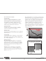 3
3
-
 4
4
-
 5
5
-
 6
6
-
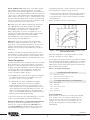 7
7
-
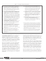 8
8
-
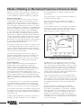 9
9
-
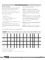 10
10
-
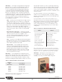 11
11
-
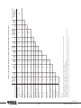 12
12
-
 13
13
-
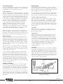 14
14
-
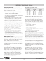 15
15
-
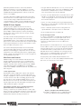 16
16
-
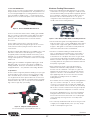 17
17
-
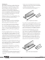 18
18
-
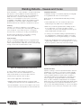 19
19
-
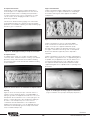 20
20
-
 21
21
-
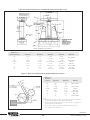 22
22
-
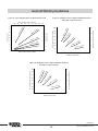 23
23
-
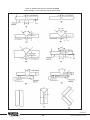 24
24
-
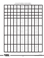 25
25
-
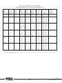 26
26
-
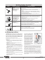 27
27
-
 28
28
-
 29
29
-
 30
30
-
 31
31
-
 32
32


Lincoln Electric KH513 Installation guide
- Category
- Welding System
- Type
- Installation guide
Ask a question and I''ll find the answer in the document
Finding information in a document is now easier with AI
Related papers
-
Lincoln Electric Guardian Control Solutions Operating instructions
-
-
-
-
-
-
Unbranded ED021274 Operating instructions
-
-
-
Other documents
-
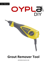 Oypla 4043 Owner's manual
-
 Trek7 rbuv16 User manual
-
Dukane Spin Welding Troubleshooting Guide Design Guide
-
-
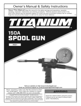 Titanium Item 56221 Owner's manual
-
Chicago Electric Item 63583 Owner's manual
-
Pipe Decor 360 KITHOOK1 Operating instructions
-
Kemppi MinarcMig Evo 200 Owner's manual
-
Snap-On MIG200i User manual
-


