Page is loading ...

Water and Industrial TI-057
Questions: Call 1-800-643-9705 or visit www.smith-blair.com
WARNING:
Do not remove retaining washer under torque-off nut.
Do not use red wedges on ductile iron pipe.
Do not use black wedges on PVC pipe.
Cam-Lock™ 120 limited to SDR 26 or heavier pipe wall.
Not for use on plain-end ttings.
Cam-Lock™ Mechanical Joint Restraining Glands are designed for use with PVC pipe (red wedges) & with ductile iron pipe
(black wedges).
PVC Cam-Lock™ (with red wedges)
Do not use RED wedges on ductile iron pipe. Cam-Lock™ 120 is designed for use on PVC pipe conforming to require-
ments of AWWA C900/C905 having cast iron OD’s, & for use on PVC pipe conforming to requirements of ASTM D-2241
having IPS (steel) OD’s. For 4”-24” sizes, Cam-Lock™ 120 is rated at the pressure rating of the pipe on which it is used, up
to 250 psi. It is rated at 150 psi for 30” & 125 psi for 36” sizes. In applications requiring UL Listed/FM Approved products,
pressure rating is 150 psi for Class 150 DR 18 pipe, 4”-12” sizes only. A standard MJ gasket is required for use on C900
pipe, a transition gasket is required for IPS pipe, or Smith-Blair Multi-Seal gasket for either. In applications requiring UL
Listed components, a UL Component Recognized mechanical joint gasket (HESZ2) must be used. Either pipe can be ac-
commodated without modication of the gland. Do not remove retaining washers under torque-off nuts.
Ductile Iron Cam-Lock™ (with black wedges)
Do not use BLACK wedges on PVC pipe. Cam-Lock™ 111 is designed for use with ductile iron pipe conforming to require-
ments of AWWA C151. Pressure rating for UL Listed/FM Approved applications in 3”-12” sizes is 350 psi. Pressure ratings
for UL Listed applications above 12” are: 350 psi for 14” & 16”, 250 psi for 18” & 24”, 200 psi for 20”. It is rated at 350 psi in
sizes 4”-16” & 250 psi in 18”-48” sizes for non-UL Listed/non-FM Approved applications. In applications requiring UL Listed
components, a UL Component Recognized mechanical joint gasket (HESZ2) must be used.
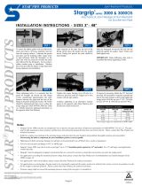
Cam-Lock™ Installation Instructions
Please read installation instructions carefully and fully.
Step 1
Wedges may have moved during transit and could prevent the Cam-Lock™ from sliding easily over pipe. Using a 1-1/4”
socket, hand-tighten torque-off nuts in a counterclockwise fashion until wedges are seated rmly against gland.
Step 2
Clean the pipe end, mechanical joint socket and gasket. Inspect the pipe, tting, and gasket for any defects and repair or
replace as necessary. Place the Cam-Lock™ gland on the plain end of the pipe with the lip extension toward the plain end.
Lubricate pipe end and gasket with soapy water or suitable pipe lubricant as per AWWA-C111/ANSI-A21.11. Slip gasket
onto the plain end with taper toward the plain end.
Step 3
Insert pipe into the socket and press gasket rmly and evenly into gasket recess. Keep joint straight during assembly.
Step 4
Push Cam-Lock™ gland toward the socket and center it around pipe with gland lip against the gasket. Insert T-bolts and
hand-tighten the nuts. Make deection (Max. 3° on 3”; 5o on 4”-12”; 2o on 14” & 16”; 1-1/2° on 18”-24”; 1° on 30”-48”) after
joint assembly but before tightening T-bolts. Note: Use T-bolts conforming to requirements of AWWA C111 only. T-Bolts of
lesser physical and chemical properties are not satisfactory.
Step 5
Tighten T-bolts while maintaining equal distance between the gland and face of the M.J. ange at all points around the
socket. This can be accomplished by partially tightening bottom T-bolt rst, then top T-bolt, next the T-bolts at either side,
and nally remaining T-bolts. Repeat the process until all T-bolts are tightened to within recommended torque range (45-60
ft-lb for 3”; 75-90 ft-lb for 4-24”; 100-120 ft-lb for 30-36”; 120-150 ft-lb for 42-48”). The use of a torque wrench is
recommended. Do not over-torque the T-bolts.
Step 6
Hand-tighten Cam-Lock™ torque-off nuts in a clockwise fashion until all wedges touch the pipe. Then tighten torque-off nuts
in an alternating pattern turning each nut ½ turn until all nuts twist off. Never turn a single torque-off nut more than ½ turn
without moving to another nut. Do not tighten further after nuts twist off. Cam-Lock™ only requires 45-60 ft-lb torque to set
wedges.
If removal and re-assembly are required, use 5/8” hex that remains after nuts have twisted off. Follow above instructions in
reverse order to completely remove the Cam-Lock™ tting. Reassemble Cam-Lock™ following above instructions, using a
torque wrench to set wedges to 45-60 ft-lb.
Installation Instructions
Type 111, 120
Cam-Lock™ Joint Restraints
for PVC and Ductile Iron Pipe
/
