Page is loading ...

INSTALLATION INSTRUCTIONS
ROMAC
INDUSTRIES,
INC.
Read installation instructions rst before installing. Check parts to ensure that no damage has occurred during transit and that no
parts are missing. Also check the diameter of the pipe and the range marked on the restrainer to ensure you have the proper size.
Document #05-9-0010 11/20/2018
21919 20th Avenue SE • Suite 100 • Bothell, WA 98021 • Phone (425) 951-6200 • 1-800-426-9341 • Fax (425) 951-6201
21919 20th Avenue SE • Suite 100 • Bothell, WA 98021 • Phone (425) 951-6200 • 1-800-426-9341 • Fax (425) 951-6201
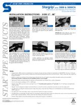
CORRECT WRONG
Special MJ Gland
GripRing
Std. MJ
Gasket
Step 3 • Insert the pipe
end into the MJ tting.
Leave 1/4" between the
pipe end and the bottom
of the MJ.
Step 1 • Clean pipe to remove as much dirt, coating,
and corrosion as possible from the surface. (Asphaltic
coating common to DI pipe does not have to be removed).
Check diameter of pipe to make sure you are using the
correctly sized GripRing. Coat both the gasket and plain
pipe end with approved lubricant.
4"-12" GripRing
™
Pipe Restrainer
Patent #5335946
Note: Make sure that the tapered side of the GripRing
faces the gland. This is very important, since the GripRing
taper engages the taper in the gland. 10 & 12" GripRings
have a Gap Cap. Do not remove Gap Cap.
Step 5 • Slide the
GripRing up the pipe until
its face is ush against the
MJ gasket. For best results,
orient the gap in the GripRing
in the down position.
Step 6 • Slide the gland
up the pipe until it engages
the GripRing.
Step 7 • Install T-bolts
in the MJ tting and gland.
Tighten hand tight.
Installation Instructions continued on back
UNI-B-13-92
R
R
Not for use on polyethylene pipe, steel pipe, plain end
mechanical joint ttings, Molecularly Oriented Polyvi-
nylchloride (PVCO) AWWA C909-02. See pipe material
compatibility chart for details.
Step 2 • Slide
the gland, GripRing,
and MJ gasket onto
the pipe end. The
GripRing should slide
easily along the pipe.
It can be sprung open
slightly if needed, to
facilitate moving it into
position.
Step 4 • Slide the gasket into
the MJ bell pocket as far as
possible. The gland (and
GripRing) may be used to
tap the gasket into place
if required. Be sure that
the gasket is properly
seated and fully pressed
into the gasket recess.

PRECAUTIONS
1. MJ gasket must comply with ANSI/AWWA C111/A21.11.
2. Check diameter of pipe to make sure you are using the cor-
rectly sized GripRing. Red rings are for IPS sized pipe, Black
rings for Cast Iron size (C900).
3. Clean pipe to remove as much dirt, coatings, and corrosion as
possible from the surface. Lubrication and additional clean-
ing should be provided by brushing both the gasket and plain
pipe end with soapy water or approved pipe lubricant per
ANSI/AWWA C111/A21.11.
4. Make sure no foreign materials become lodged between the
GripRing and pipe, gasket and GripRing, or between the
GripRing and gland.
5. Avoid loose tting wrenches, or wrenches so short that
achieving proper torque is difcult.
6. Keep threads free of foreign material to allow proper tight-
ening.
7. Bolts are often not tightened enough when a torque wrench
is not used. Take extra care in this situation to make sure
bolts are properly tightened.
8. Pressure test for leaks before backlling.
9. If a good seal is not attained at 90 ft-lbs torque, the joint
should be disassembled, thoroughly cleaned, and carefully
reassembled. Leave 1/4" between the pipe and the bottom
of the MJ.
10. Backll and compact carefully around pipe and ttings.
11. When reinstalling parts with stainless steel hardware there
may be a loss in pressure holding ability due to worn or dam-
aged threads during the original installation.
COMMON INSTALLATION ERRORS
1. Not enough torque on bolts.
2. Debris lodged between GripRing and pipe/gasket/gland.
3. Dirty threads on bolts or nuts.
4. Not using the proper size GripRing for the pipe.
5. Allowing the gland to get cocked at an angle to the bell ange.
6. Forgetting to install the GripRing (provides gasket seal, but
no restraint).
7. Gasket not properly seated.
IF GRIPRING MUST BE REMOVED
GRIPRING
™
PIPE MATERIAL COMPATIBILITY CHART
Pipe Material Ring Color Working Pressure Comments
* Ductile Iron - AWWA C151 Black 350
Cast Iron - Obsolete Std. Black 350 OD is same as DI, C151
* PVC - D.I. Size AWWA C900 Black Rating of pipe Class 235 (SDR18) & 305 (SDR14) only.
PVC - “Class Pipe” ASTM D2241 Red Rating of pipe
4"-8" Class 160 (SDR26) - 200 (SDR21). 10" & 12" Class 200 only.
PVC - Sched. 80, ASTM D1785 Red Rating of pipe 4"-8" Class Sched 40-80. 10" & 12" Sched. 80 only.
PVC C900 DR Class 100/165 (DR25)
– –
GripRing is not for use on C900 DR Class 100/165 (DR25) pipe.
PVC Molecularly Oriented (C909) – – GripRing is not for use on C909 pipe
Steel – – GripRing is not for use on steel pipe
Asbestos Cement – – GripRing not for use on asbestos cement
Fiberglass – – GripRing not for use on berglass pipe
HDPE – – GripRing not for use on HDPE pipe
Plain end mechanical joint ttings – – GripRing not for use on plain end MJ ttings
* UL Listed & FM Approved
Nominal Size Bolt Size Torque
4", 6" & 8"
3
/4" 75-90 ft-lbs
10" & 12"
3
/4" 90-110 ft-lbs
NOTE: Angular deection of up to 5° is allowable
between the pipe and tting for all GripRing sizes.
Equal distance must be maintained between
the gland and the tting throughout the
installation, until the proper torque is achieved.
For best results, torque to proper torque, then
wait 10 minutes and retorque.
Proper torque is necessary to get a proper
gasket seal and assure that the GripRing
engages the pipe to provide restraint.
Pressure test before backlling.
ROMAC INDUSTRIES, INC. • 4" - 12" GripRing
™
Installation Instructions (cont.from front).
Step 8 • Using a torque wrench, tighten the
nuts to the proper torque shown on torque chart
(below). Care must be taken to assure that
the anges of the gland and MJ tting remain
parallel during the entire installation. This can be
done by alternating side-to-side while tightening.
IF GRIPRING MUST BE REMOVED
1. Make sure pipe is not pressurized. Disassembling the joint
compromises gasket seal and restraint.
2. Remove all bolts and nuts from gland. Slide gland away from
MJ bell, disengaging it from the GripRing.
3. Pry open the GripRing gap to approximately 3/4" using a
screw driver, snap ring pliers, or other available tool. This
will disengage the GripRing from the pipe.
/