Page is loading ...

1
SIGMA Corporation www.sigmaco.com
700 Goldman Drive
Cream Ridge, NJ 08514
800 999 2550 p
609 758 1163 f
SIGMA Corporation
www.sigmaco.com
ONE-LOK
™
Series SLDE for Ductile Iron Pipe
1) The SIGMA ONE-LOK Series SLDE is a mechanical joint restraining gland that
implements a series of individually activated wedges into the mechanical joint follower
gland. When the wedge segment is engaged by the actuating bolt, the primary contact
edges of each wedge segment lock onto the pipe wall. This action causes the primary
contact edges to grip the pipe and eectively restrain all classications of ductile iron
pipe.
2) ONE-LOK SLDE’s precision contoured wedges provide proper contact and support
of the ductile iron pipe wall. Each wedge is manufactured with an elongated contour that
evenly matches the outside circumference of each nominal diameter of ductile iron pipe.
This elongated contour also eliminates the concern of damage to both the pipe wall and
the interior cement mortar lining caused by point loading, even on the thinner pressure
classes of ductile iron pipe.
3) ONE-LOK SLDE’s wedge actuating bolt provides the installer with a visual torque
indicator. The breakaway top ensures proper engagement of the wedge segment at the
time of installation. Unlike other actuating bolts, the ONE-LOK SLDE is manufactured
with a proprietary quality control system that ensures the breakaway tops will activate
at the correct torque. The breakaway top is sized to match the same dimensions of
the bolts and nuts used to assemble the mechanical joint tting and follower gland,
eliminating the need for special installation tools. Once engaged, the actuating bolt
leaves a residual hex-head shank, allowing post-installation disassembly of the
restrained joint, if necessary.
4) ONE-LOK SLDE’s unique wedge segment and actuating bolt design allows the two
components to interface using a cam action principle, allowing the wedge segments
to rock and increase their grip on the pipe wall as thrust on the assembled joint
increases. This also allows improved resistance to subsidence, seismic forces, and
other movement within the maximum deection limitations of the mechanical joint under
applicable AWWA standards
.
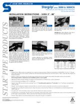
ONE-LOK’s unique cam action allows the restraining wedges
to “rock,” gripping the pipe wall more securely as thrust force
increases.
ONE-LOK’s cam action also accommodates deection of the
joint during installation, and also allows for subsidence, seismic
or other forces after installation, up to the maximum allowed
deection.
Nominal Size Item # Deection
3-12” SLDE3-SLDE12 5 deg
14-16” SLDE14-SLDE16 2 deg
18-30” SLDE18-SLDE30 1.5 deg
36-64” SLDE36-SLDE64 1 deg
Deection Chart
Features & Advantages:

2
SIGMA Corporation www.sigmaco.com
ONE-LOK
™
Series SLDE for Ductile Iron Pipe
Sample Specication:
Restraint for standard mechanical joint ttings shall be incorporated in the design of the follower gland and shall utilize multiple
wedge segments that act against the pipe, increasing their resistance as the line pressure increases. The assembled joint
shall maintain the maximum exibility and deection of all nominal pipe sizes after burial. Restraining gland, wedge segments,
and actuating bolts shall be manufactured of high strength ductile iron conforming to the requirements of ASTM A536, Grade
65-45-12. Wedge segments shall be heat treated to a hardness of 370 BHN minimum. Dimensions shall be compatible
with standardized mechanical joints conforming to the requirements AWWA C111/ANSI A21.11 and AWWA C153/ANSI 21.53
through 24” (latest revision). Breakaway tops shall be incorporated in the design of the actuating bolts to visually ensure
proper torque. The manufacturing of the actuating bolt must incorporate a quality control procedure that is deemed acceptable
by the specier and positively assures precise and consistent operating torque of the breakaway top. The mechanical joint
restraining devices shall have a working pressure rating of 350psi (for sizes 3-16”) and 250 psi (for sizes 18-64”) minimum
and provide no less than a safety factor of 2:1. Restraint shall be UL Listed and FM approved in applicable sizes. Restraining
device shall be SIGMA ONE-LOK™ or approved equal.
Dimensions in Inches, Weights in Pounds
Nom
Pipe
Size
Item # Wgt
Pipe
OD
Dimensions Bolts and Inserts
Pressure
Rating
T-bolts Gasket
C F D T P* B J K2 No Size Torque No Size Torque No Item #
3 SLDE3 5.50 3.96 4.84 4.16 1.58 0.55 9.40 0.750 6.19 7.69 2 7/8 80-90 350 4 5/8 x 30 80-90 1 TG-3
4 SLDE4 6.50 4.80 5.92 5.00 1.58 0.55 10.24 0.875 7.50 9.12 2 7/8 80-90 350 4 ¾ x 35 80-90 1 MG-4
6 SLDE6 10.00 6.90 8.02 7.10 1.58 0.60 12.34 0.875 9.50 11.12 3 7/8 80-90 350 6 ¾ x 35 80-90 1 MG-6
8 SLDE8 14.50 9.05 10.17 9.25 1.63 0.75 14.32 0.875 11.75 13.37 4 7/8 80-90 350 6 ¾ x 40 80-90 1 MG-8
10 SLDE10 23.00 11.10 12.22 11.30 1.58 0.85 16.54 0.875 14.00 15.62 6 7/8 80-90 350 8 ¾ x 40 80-90 1 MG-10
12 SLDE12 29.00 13.20 14.32 13.40 1.58 0.85 18.80 0.875 16.25 17.88 8 7/8 80-90 350 8 ¾ x 40 80-90 1 MG-12
14 SLDE14 39.60 15.30 16.40 15.55 1.58 1.125 21.20 0.875 18.75 20.25 10 7/8 80-90 350 10 ¾ x 45 80-90 1 MG-14
16 SLDE16 49.67 17.40 18.50 17.54 1.77 1.21 23.74 0.875 21.00 22.50 12 7/8 80-90 350 12 ¾ x 45 80-90 1 MG-16
18 SLDE18 60.33 19.50 20.60 19.64 1.77 1.25 25.84 0.875 23.25 24.75 12 7/8 80-90 250 12 ¾ x 45 80-90 1 MG-18
20 SLDE20 69.00 21.60 22.70 21.74 1.87 1.25 27.94 0.875 25.50 27.00 14 7/8 80-90 250 14 ¾ x 50 80-90 1 MG-20
24 SLDE24 103.67 25.80 26.88 25.95 1.92 1.47 32.14 0.875 30.00 31.50 16 7/8 80-90 250 16 ¾ x 50 80-90 1 MG-24
30* SLDE30 158.67 32.00 33.29 32.17 2.13 1.65 39.30 1.125 36.88 39.12 20 1.00 115-125 250 20 1 x 65 100-120 1 MGS-30
36* SLDE36 234.50 38.30 39.59 38.47 3.15 1.75 46.07 1.125 43.75 46 24 1.00 115-125 250 24 1 x 65 100-120 1 MGS-36
42* SLDE42 344.00 44.50 45.79 44.67 3.56 2.25 53.25 1.38 50.62 53.38 28 1 1/4 115-125 250 28 1 ¼ x 80 100-120 1 MGS-42
48* SLDE48 456.00 50.80 52.09 50.97 3.81 2.25 59.55 1.38 57.5 60.26 32 1 1/4 115-125 250 32 1 ¼ x 80 100-120 1 MGS-48
54* SLDE54 1045.00 57.56 58.85 57.73 6.00 4.50 70.43 1.375 63.20 67.50 18 1½ 400 +/- 5 250 36 1 ¼ x 110 150 - 200 1 MGS-54
60* SLDE60 1136.00 61.61 62.90 61.78 6.00 4.50 74.52 1.375 67.72 72.00 18 1½ 400 +/- 5 250 36 1 ¼ x 110 150 - 200 1 MGS-60
64* SLDE64 1258.00 65.67 66.96 65.84 6.00 4.50 78.68 1.375 71.86 76.00 19 1½
400 +/- 5 250 38 1 ¼ x 110 150 - 200 1 MGS-64
ONE-LOK SLDE was previously referred to as model SLD
Sizes 3” - 36” are UL listed
Sizes 4” - 12” are FM approved
P* Dim shows OD after head is broken/removed.
Sizes 3”-12” is approved for thinnest class of DI pipe.
* Product is provided with SIGMASEAL™ improved mechanical joint gasket.
Materials:
• Gland body, brackets, wedge segments & actuating bolts: ASTM A536 65-45-12 ductile iron.
• Wedge segments are heat treated to a minimum hardness of 370BHN
• T-head bolts & nuts: High strength, low alloy steel meeting AWWA/ANSI C111/A21.11 with minimum 65,000psi tensile
strength and 45,000psi yield strength.

3
SIGMA Corporation www.sigmaco.com
Installation Instructions:
Note: This product is designed for use on ductile iron pipe. Contact SIGMA for use on plain end ttings.
1. Clean tting socket and pipe end. Lubricate gasket and pipe end with soapy water (or approved pipe lubricant
meeting AWWA C111). Install ONE-LOK™ restrainer on the pipe with the lip extension facing the pipe end, followed
by the gasket, tapered side toward end of pipe.
NOTE: SIGMASEAL Gasket is recommended for ONE-LOK 30-64”. When installing SIGMASEAL gasket, the
tapered edges of the gasket must face away from the pipe wall.
2. Insert pipe into tting outlet and seat the gasket rmly and evenly into the gasket cavity. Maintain a straight joint
during assembly.
3. Push the ONE-LOK gland toward the tting and center it around the pipe with the lip evenly against the gasket.
Insert the T-bolts and hand tighten the nuts. If deection is required, make up after joint assembly but before
tightening T-bolts.
4. Tighten T-bolts in an alternating manner maintaining an even gap between the gland and the tting face at all
points around the socket. Repeat alternate tightening cycle of of the t-bolts until one full cycle is completed where
each individual t-bolt maintains the recommended torque.
5. Following proper assembly of the mechanical joint, hand tighten actuating bolts until all wedges make complete
contact with the pipe.
6. Tighten each actuating bolt in a clockwise direction, alternating between the bolts in a star pattern, until the
break-o tops have been removed. Never tighten a wedge bolt more than 180 degrees before moving to the next
bolt.
September 2015 SIGMA Corporation

4
SIGMA Corporation
• 2-64” C153 Ductile Iron Mechanical Joint Class 350
• 2-48” C110 Full Body Mechanical Joint
• 2-64” C110 Cast Iron/Ductile Iron Flanged Fittings
• 3-24” C153 TRIM TYTON ® Compact Push On Fittings
• 4-24” C110 Full Body Push On Fittings
• C116 Fusion Bonded Epoxy lining avaiable
• PROTECTO 401
®
ceramic epoxy lining available
• Prepackaged and loose mechanical joint accessories
• SIGMASEAL
™
improved mechanical joint gasket
• Snap-on multi-purpose gasket for ductile iron or PVC pressure pipes
• Ductile iron set screw retainer glands
• OMNI-SLEEVE
™
improved wall penetration sleeve
• Specialty bolts and nuts for mechanical joint assemblies
• 3-36” SIGMAFLANGE SFA ange adapter sleeve for PVC and DIP
• 2-48” ZIP FLANGE set screw style ange adapter
• Manhole Rings and Covers
• Curb and Meter Boxes
• Frames and Grates
• Storm Inlets
• Valve Boxes, Risers, and Extensions
• 3-64” High Hub Threaded Flanges
• 3-48” Tapped High Hub Threaded Flanges
• 3-36” Extra Heavy 250lb Drilled Threaded Flanges
• 3-48” Threaded MJ Bell Adapters
• 3-48” MJ x PE Bell adapter (2ft)
• 3-48” Anchor Flanges
• 3-16” Filler Flanges
• FLANGE-PAK™ prepackaged ange accessory sets
• Polyethylene encasement for ductile iron pipe
• Copper tubing products
• Tracer wire & detectable/non-detectable marking tape
• Pipe joint lubricant & hydraulic cement
• Socket clamps and tie rod accessories
• BOXLOK Valve Box Alignment Device
• Cast Iron Companion Flanges
© July 2015 SIGMA Corporation All rights reserved.
Line Card
TRIM-TYTON and TYTON are registered trademarks of the United States Pipe and Foundry Company • PROTECTO 401 is a registered trademark of Induron, Inc.
www.sigmaco.com
Terms and Conditions of Sales available at our website.
LOCATIONS
Northeast Region
Cream Ridge, New Jersey (HQ)
700 Goldman Drive
Cream Ridge, NJ 08514
Phone (800) 999-2550
Fax (609) 758-1158
REPCO
970 DE LA Bastican
Victoriaville, Quebec G6T 1Y2
Phone (888) 744-6262
Fax (819) 758-1153
Concord Supply
2353 Bowman Street
Innisl, Ontario L9S 3V6
Phone (877) 436-3800
Fax (705) 436-6338
tanya@concordsupply.ca
Midwest Region
Sauk Village, Illinois
21699 Torrence Avenue
Sauk Village, IL 60411
Phone (888) 999-0420
Fax (708) 758-6790
Southeast Region
Alexander City, Alabama
1500 Highway 22 W
Alexander City, AL 35010
Phone (800) 824-4513
Fax (256) 234-4956
Southwest Region
Houston, Texas
5000 Askins Lane
Houston, TX 77093
Phone (800) 999-0109
Fax (281) 987-0200
Western Region
Ontario, California
4652 E. Guasti Road
Ontario, CA 91761
Phone (800) 688-6230
Fax (909) 391-2033
Auburn, Washington (Branch)
902 W Main Street
Auburn, WA 98001
Phone (800) 688-6230
Fax (909) 391-2033
AWWA Ductile Iron Fittings
Mechanical Joint Accessories
ONE-LOK
™
Wedge Action Restraints
PV-LOK
™
Serration Lock Restraints
Flange Adapters
Municipal Construction Castings
Products for the Ductile Iron Fabricator
Extended Range Products
• 3-48” ONE-LOK SLDE restraint for ductile iron pipe (import or domestic)
• 54”-60”-64” ONE-LOK SLDE restraint for ductile iron pipe (import)
• 3-36” ONE-LOK SLCE restraint for PVC pipe (import or domestic)
• 3-36” ONE-LOK SLDEH bell joint harness for ductile iron pipe
• 4-12” / 20” ONE-LOK SLDM restraint for oversized cast iron pipe
• 4-36” ONE-LOK SSLD split restraint for existing ductile iron pipe
• 4-36” ONE-LOK SSLDH split restraint harness for existing ductile iron pipe
• 3-12” ONE-LOK SLCEH bell joint harness for PVC pipe
• 4-48” PV-LOK PWM Restraint for MJ Fitting to PVC pipe
• 4-48” PV-LOK PWP Restraint for PVC bell joint restraint
• 4-12” PV-LOK PWP Restraint for PVC bell joint restraint (domestic)
• 4-48” PV-LOK PWPF Restraint for PVC tting to PVC pipe
• 4-12” PV-LOK PWH PVC bell joint harness
• 2-12” PV-LOK PVM Restraint for MJ Fitting to IPS PVC pipe
• 2-12” PV-LOK PVP Restraint for IPS PVC pipe bell joint
• 4-8” PV-LOK PVPF Restraints for IPS PVC pressure tting
/