62219501200031

Smith Blair Inc 62219501200031, 622-22680400-003, 62213201200231, 62215300600003 Installation guide

  • Hello! I am an AI chatbot trained to assist you with the Smith Blair Inc 62219501200031 Installation guide. I’ve already reviewed the document and can help you find the information you need or explain it in simple terms. Just ask your questions, and providing more details will help me assist you more effectively!
Installation
Instructions
622
Tapping Sleeve
Questions: Call 1-800-643-9705 or visit www.smith-blair
.com
Sheet 1 of 2 Rev 2/6/20
Water
TI-019
STEP 1
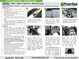
Inspect the shipment received to ensure no damage has occurred during transit or storage and no hardware is missing.
Ensure the tapping sleeve is the proper type, tap size, and correct pipe size range for the installation prior to
beginning.
STEP 2
Clean the pipe surface thoroughly, particularly in the area where the gasket
will seat. Remove any scale, dirt, or debris that could affect the gasket seal.
STEP 3
Check the pipe outside diameter where the tapping sleeve will be installed to
ensure that the correct tapping sleeve is being used.
NOTE: Pipe must be round in the area where sleeve will be installed (See Roundness Table)
STEP 4
Remove the nuts, washers, and bolts, then the bottom half of the tapping sleeve (See Figure 2).
STEP 5
Verify that the gasket is secure in the gasket groove (See Gasket Detail), then lubricate the pipe
and gasket with a non-detergent soap solution. Ensure the lubricant does not freeze.
STEP 6
Mount the sleeve halves on the pipe with the test outlet accessible and the flanged portion of the sleeve facing the
connecting pipe. To prevent gasket failure, do not slide or rotate the tapping sleeve while mounted on the pipe.
STEP 7
Install the bolts and washers, then hand tighten the nuts with equal gaps between the sleeve halves (See Figure 3).
*Stainless bolts, washers, and nuts will be supplied with a nylon washer which is used between the nut and washer.
STEP 8
Tighten the nuts starting from the center outward, alternating from side to side, to maintain uniform spacing between
the sleeve halves (See Figure 5). Continue to tighten the nuts until the sleeve halves form to the contour of the pipe,
and all nuts are tightened to the specified torque (See “Bolt Torque” Table).
STEP 9
Proper blocking of the valve and/or tapping equipment is required. Improper blocking will cause the sleeve to pull
away from the pipe and proper torque will not be achieved (See Figure 4). On some installations, the valve and/or
tapping machine may be installed on the sleeve prior to hoisting into the trench.
STEP 10
Following the manufacturer’s instructions, install the tapping valve while providing thrust blocking and a permanent
support beneath the valve.
NOTE: Smith-Blair recommends using 1/8” thick, ring style elastomeric valve flange gaskets. For mechanical
joint (MJ) outlets use only gaskets, hardware, and installation procedure per AWWA C111.
STEP 11
Hydrostatic pressure test the tapping sleeve, flange gasket, and tapping valve to ensure all joints are tight and that
gaskets are properly seated.
Do Not Air Test! Use Hydrostatic Test Only! Pressure test should not exceed 1.5 times actual line pressure.
For pipe diameters larger than 36”: pressure test to 50 - 75 psi; release pressure; re-torque all nuts; pressure test to full
pressure.
STEP 12
Using the tapping machine’s manufacturer instructions, install the tapping machine to the valve and perform the tap.
NOTE: A 1/2” under size cutter is required for size-on-size applications. Confirm proper clearance between the
cutter and neck/outlet inside diameter.
STEP 13
Re-torque all nuts to the specified torque. If possible, nuts should be checked 12-24 hours after installation.
Gasket Detail
USE OF A CALIBRATED
TORQUE WRENCH IS
RECOMMENDED!
Installation
Instructions
622
Tapping Sleeve
Questions: Call 1-800-643-9705 or visit www.smith-blair
.com
Sheet 2 of 2 Rev 2/6/20
Water
TI-019
ARRANTY
Smith-Blair, Inc. warrants its products to be free of defects in materials and workmanship for a period of one (1) year from the date of shipment by
Smith-Blair, Inc. (the "Warranty Period"). Dated proof of purchase, such as a bill of sale, is required to establish warranty eligibility. If a product fails
to perform due to a defect in materials or workmanship during the Warranty Period, Smith-Blair, Inc. will repair or, at Smith Blair, Inc.'s option,
replace the product with the same or comparable item. In the event that the product cannot be repaired and a suitable replacement item is not
available, Smith-Blair, Inc. will refund the original purchase price shown on the proof of purchase. In all cases, the customer is responsible for
returning the allegedly defective product to the factory or warehouse designated by Smith-Blair, Inc.
THIS LIMITED WARRANTY IS EXCLUSIVE AND IS IN LIEU OF ANY EXPRESS OR IMPLIED WARRANTY OF MERCHANTABILITY, FITNESS
FOR A PARTICULAR PURPOSE, OR OTHER WARRANTY OF QUALITY, OR THOSE ARISING FROM A COURSE OF DEALING, CUSTOM, OR
USAGE OF TRADE. THE REMEDIES PROVIDED IN THIS LIMITED WARRANTY STATEMENT ARE THE CUSTOMER'S SOLE AND EXCLUSIVE
REMEDIES. IN NO EVENT SHALL SMITH-BLAIR, INC. BE LIABLE FOR DIRECT, INDIRECT, SPECIAL, INCIDENTAL, OR CONSEQUENTIAL
DAMAGES, WHETHER BASED ON CONTRACT, TORT, OR ANY OTHER LEGAL THEORY, AND WHETHER ADVISED OF THE POSSIBILITY
04/18
Metal products are subject to corrosion, particularly when used outdoors and/or underground. A large number of factors and local conditions af
the rate of corrosion. Consult a local corrosion expert determine the life expectancy of this product when used with your pipeline content, soil, and
environment. Also, consult your system designer to determine the suitability of this product in your piping system. Failure to determine the suitability
of this product in your application, soil, and/or environment can result in premature product failure. Smith-Blair will provide additional information
04/18
/