BAPI 49584 User manual

Type
User manual

The BAPI 49584 EZ Pressure Sensor is a versatile and accurate device designed to measure differential pressure in various applications. With its ±5 inches W.C. (±1,250 Pascals) accuracy and field-selectable pressure ranges, it provides precise measurements for a wide range of scenarios. The user-friendly interface, including a rotary switch and NEXT button, allows for easy selection of pressure range, output range, and unit mode (Inches W.C. or Pascals). The EZ Pressure Sensor can be mounted on DIN rails, Snaptrack, or surfaces, making it adaptable to different installation requirements.

The BAPI 49584 EZ Pressure Sensor is a versatile and accurate device designed to measure differential pressure in various applications. With its ±5 inches W.C. (±1,250 Pascals) accuracy and field-selectable pressure ranges, it provides precise measurements for a wide range of scenarios. The user-friendly interface, including a rotary switch and NEXT button, allows for easy selection of pressure range, output range, and unit mode (Inches W.C. or Pascals). The EZ Pressure Sensor can be mounted on DIN rails, Snaptrack, or surfaces, making it adaptable to different installation requirements.

49584_ins_EZPS_Standard_Range.pdf
Building Automation Products, Inc., 750 North Royal Avenue, Gays Mills, WI 54631 USA
Tel:+1-608-735-4800 • Fax+1-608-735-4804 • E-mail:[email protected] • Web:www.bapihvac.com
EZ Pressure Sensor, Standard Pressure Ranges
Installation and Operation Instructions
rev. 12/08/2022
1 of 4
BAPI’s EZ Pressure Sensor is a true dierential pressure
transmitter that provides ±5 inches W.C. (±1,250 Pacals)
in 10 eld selectable ranges (see specications). BAPI’s
EZ enclosure is designed for DIN rail, Snaptrack or surface
mounting. Five output ranges of 0 to 5, 1 to 5, 0 to 10 and
2 to 10 VDC and 4 to 20 mA are also eld selectable for all
pressure ranges. The wiring terminal block is pluggable.
Pressure units of inches of Water Column or Pascals are eld
selectable.
Identication and Overview
Fig. 1: EZ Pressure Sensor
Mounting
The EZ Mount Base has mounting tabs that can be
extended or pushed in for the three mounting methods.
DIN Rail Mounting, Figs 2-3:
Pull out the blue mounting tabs.
Catch the EZ mount hook on DIN rail as shown in Fig 3.
Rotate the EZ pressure module down until the bottom
mounting tab snaps into place on the DIN rail.
Connect wires and pressure lines as needed.
Snaptrack Mounting, Fig 4:
Push in the blue mounting tabs.
Snap the EZ Mount base into the board slots in the 2.75
inch snaptrack.
Connect wires and pressure lines as needed.
Surface Mounting, Fig 5:
Pull out the blue mounting tabs.
Place the EZ Pressure unit against the surface and
mark the screw holes.
Drill 1/8” pilot holes for #8 athead screws.
Screw unit to the surface. The holes in the blue
mounting tabs are elongated to allow for alignment.
Connect wires and pressure lines as needed.
Snaptrack Mount Surface
Mount
Fig. 2: DIN Rail
Mounting with tabs out
DIN Rail
Mount
Fig. 3: Catch the EZ Mount
hook on the edge of the DIN
Rail, then rotate into place
Fig. 4: Snaptrack
Mounting with tabs in
Fig. 5: Surface
Mounting with the tabs
out
Pressure Connections
Fig. 6: Pressure
Port Connections
The Pressure ports are 1/4” barbed ttings.
Connect the high pressure to the port labeled High
Connect the low pressure to the port labeled Low
The output will be the pressure dierence between the high and low
port.
49584_ins_EZPS_Standard_Range.pdf
Building Automation Products, Inc., 750 North Royal Avenue, Gays Mills, WI 54631 USA
Tel:+1-608-735-4800 • Fax+1-608-735-4804 • E-mail:[email protected] • Web:www.bapihvac.com
EZ Pressure Sensor, Standard Pressure Ranges
Installation and Operation Instructions
rev. 12/08/2022
2 of 4
Wiring Termination
4 to 20 mA, “Two Wire” Operation
Connect the EZ Pressure’s [Power] terminal to a DC voltage of 7 to 40 VDC.
Connect the [Gnd/4-20 mA Out] terminal to a 4 to 20mA input on your controller.
The [Voltage Out] terminal is not used for 4 to 20 mA signaling.
0 to 5, 1 to 5, 0 to 10 or 2 to 10 V, “Three Wire” Operation
Connect the EZ Pressure’s [Power] terminal to:
7 to 40 VDC or 6 to 28 VAC (for 0 to 5 or 1 to 5 VDC output units)
12 to 40 VDC or 9 to 28 VAC (for 0 to 10 or 2 to 10 VDC output units).
Connect the terminal labeled [Gnd/4-20 mA Out] to the controller’s ground.
Connect the [Voltage Out] terminal to an analog input congured for voltage input.
Note: The terminals use a rising block screw terminal to hold the wires. It is possible for the
block to be in a partially up position allowing the wire to be inserted under the block. Be sure that the connector screws
are turned fully counterclockwise before inserting the wire. Lightly tug on each wire after tightening to verify proper
termination.
Fig. 7: Wiring
terminations
Output Signal Power Terminal Gnd/4-20mA Terminal Voltage Output Terminal
4 to 20 mA 7 to 40 VDC 4 to 20 mA Signal To Controller Analog Input Not Used
0 to 5 VDC 7 to 40 VDC or 6 to 28 VAC To Controller Ground 0 to 5 VDC Signal To Controller Analog Input
1 to 5 VDC 7 to 40 VDC or 6 to 28 VAC To Controller Ground 1 to 5 VDC Signal To Controller Analog Input
0 to 10 VDC 12 to 40 VDC or 9 to 28 VAC To Controller Ground 0 to 10 VDC Signal To Controller Analog Input
2 to 10 VDC 12 to 40 VDC or 9 to 28 VAC To Controller Ground 2 to 10 VDC Signal To Controller Analog Input
Table 1: EZ Pressure Sensor Termination
Front Panel Operation
The rotary switch is used to select the pressure range, bi-directional or uni-directional pressure range, output range
or to auto zero the unit. The notch in the knob indicates the switch position. The rotary switch in Fig. 8 is indicating 0
(zero), showing that the switch is in the Auto Zero position.
Pressing the NEXT button toggles between values when the rotary switch is in the [+/-]
bi-directional or uni-directional pressure or [OUT] output range position. The NEXT button is
also used to initiate [0] Auto Zero or change the display mode.
AUTO ZERO SELECT (Table 2)
Connect the high and low ports together with a short length of tubing without kinks.
Place the rotary switch into the [0] position. The display will show Aut0.
Press the NEXT button. The display will show a series of progress bars starting with one
bar and ending with four.
When the Auto Zero is complete, the display will
show “done” for about 4 seconds, then Aut0.
Return the rotary switch to the desired pressure
range (see Pressure Range Select).
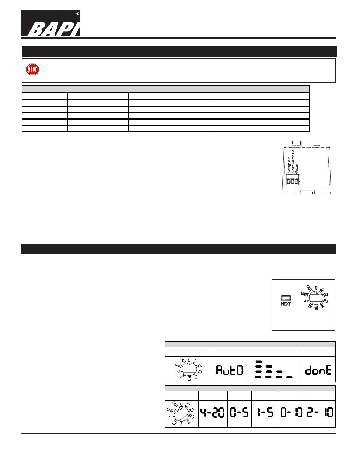
OUTPUT RANGE SELECT (Table 3)
Place the rotary switch into the [OUT] position.
Press the NEXT button until the desired output
range is showing on the display.
Return the rotary switch to the desired pressure
range (see Pressure Range Select).
Rotary Switch Position Initial Display After Pushing NEXT button When Complete
Table 2: Auto Zero Display Sequence
Rotary Switch
Position
4 to 20 mA
Output
0 to 5 VDC
Output
1 to 5 VDC
Output
0 to 10 VDC
Output
2 to 10 VDC
Output
Fig. 8: Front Panel
Controls
BAPI recommends wiring the product with power disconnected. Proper supply voltage, polarity and wiring
connections are important to a successful installation. Not observing these recommendations may damage the
product and void the warranty.
49584_ins_EZPS_Standard_Range.pdf
Building Automation Products, Inc., 750 North Royal Avenue, Gays Mills, WI 54631 USA
Tel:+1-608-735-4800 • Fax+1-608-735-4804 • E-mail:[email protected] • Web:www.bapihvac.com
EZ Pressure Sensor, Standard Pressure Ranges
Installation and Operation Instructions
rev. 12/08/2022
3 of 4
Front Panel Operation continued....
Rotary Switch Position Inches W.C. Pascals
Table 4: Pressure Range Select Display Sequence
Fig. 10: Duct static pressure monitoring with the
BAPI EZ Low Pressure Sensor mounted in a panel
with a static probe (ZPS-ACC07) in the duct.
Typical Applications
Fig. 11: Air lter pressure drop monitoring with the EZ
Low Pressure Sensor mounted in a panel with two static
pressure probes (ZPS-ACC07) in the duct.
NOTE: Best practice is to form a drip loop in the tubing to prevent condensation from reaching the sensor.
UNIT MODE SELECT
You have the ability to toggle between Inches W.C. and Pascals by pressing the next button
when the rotary switch is in the UNIT position. When the unit is measuring in Inches W.C. the
unit will display In. When the unit is measuring in Pascals the unit will display PA.
Fig. 9: Rotary Switch
Position for Unit Mode
Selection
PRESSURE RANGE SELECT (Table 4)
Rotate the rotary switch to any of the positions labeled [R1] through
[R5] or [CR] for a Custom Range. (Note: Custom Range units will
have the pressure range printed on the label.) The display will show
the pressure range for 2 to 4 seconds, and then the display shows the
dierential pressure across the ports.
UNI-DIRECTIONAL OR BI-DIRECTIONAL RANGE SELECT
(Table 5)
All pressure ranges can be made uni-directional or bi-directional.
Place the rotary switch into the [+/-] position. The directional mode
will show on the display.
Press the NEXT button until the desired mode is showing on the
display.
Return the rotary switch to the desired pressure range.
Rotary Switch Position Uni-Directional Pressure Bi-Directional Pressure
Table 5: Uni-Directional or Bi-Directional Mode Display
49584_ins_EZPS_Standard_Range.pdf
Building Automation Products, Inc., 750 North Royal Avenue, Gays Mills, WI 54631 USA
Tel:+1-608-735-4800 • Fax+1-608-735-4804 • E-mail:[email protected] • Web:www.bapihvac.com
EZ Pressure Sensor, Standard Pressure Ranges
Installation and Operation Instructions
rev. 12/08/2022
Specications subject to change without notice.
Power:
7 to 40 VDC (4 to 20 mA Output)
7 to 40 VDC or 6 to 28 VAC (0 to 5 or 1 to 5 VDC Output)
12 to 40 VDC or 9 to 28 VAC (0 to 10 or 2 to 10 VDC Output)
Power Consumption:
20 mA max, DC only at 4 to 20 mA Output
4.9 mA max DC at 0 to 5 or 0 to 10 VDC Output
0.12 VA max AC at 0 to 5 or 0 to 10 VDC Output
Load Resistance:
4 to 20 mA Output 850 Ω Maximum @ 24 VDC
0 to 5, 1 to 5, 0 to 10, 2 to 10 VDC Output 6Ω min.
Accuracy:
±0.25% FS at 72°F (22°C) for All Units
±0.025” WC (±6.22 Pa)
Stability: ±0.25% F.S. per year
Overpressure:
Proof: 200” WC (7.21 PSI)
Burst: 300” WC (10.82 PSI)
Media: Clean, dry, non-corrosive gases
Compensated Temperature Range:
32 to 122°F (0 to 50°C)
Environmental Operating Range:
14°F to 140°F (-10°C to 60°C)
Storage Temp.: -40 to 203°F (-40 to 95°C)
Humidity: 0 to 95% RH, non-condensing
Wiring:
Removable terminal block (14 to 24 AWG)*
2 wires (4 to 20mA Current loop)*
3 wires (AC or DC powered, Voltage out)*
Port Size: 1/4” barb (1/8” to 3/16” I.D.)
Enclosure Material: ABS Plastic, UL94 V-0
Mounting: DIN Rail, Snaptrack or Surface
Agency: RoHS, UL
*BAPI recommends that you do not run wiring for
the pressure transmitter in the same conduit as line
voltage wiring or with wiring used to supply highly
inductive loads such as motors, generators and coils.
4 of 4
Specications
Range Pressure Range Pressure Range Pressure Range Pressure
71 0 to 1.00" 76 ± 1.00" 81 0 to 250 Pa 86 ± 250 Pa
72 0 to 2.00" 77 ± 2.00" 82 0 to 300 Pa 87 ± 300 Pa
73 0 to 2.50" 78 ± 2.50" 83 0 to 500 Pa 88 ± 500 Pa
74 0 to 3.00" 79 ± 3.00" 84 0 to 1,000 Pa 87 ± 1,000 Pa
75 0 to 5.00" 80 ± 5.00" 85 0 to 1,250 Pa 90 ± 1,250 Pa
Table 6: Pressure Ranges
Inches of Water Column (WC) Ranges Pascal Ranges
Troubleshooting
POSSIBLE PROBLEMS:
Display does not light
Output stuck either high or low or
not tracking pressure properly.
POSSIBLE SOLUTIONS:
- Check power connections for proper power (see specications below).
- Remove pressure from ports and perform Auto Zero procedure
described on page 2.
  • Page 1 1
  • Page 2 2
  • Page 3 3
  • Page 4 4

BAPI 49584 User manual

Type
User manual

The BAPI 49584 EZ Pressure Sensor is a versatile and accurate device designed to measure differential pressure in various applications. With its ±5 inches W.C. (±1,250 Pascals) accuracy and field-selectable pressure ranges, it provides precise measurements for a wide range of scenarios. The user-friendly interface, including a rotary switch and NEXT button, allows for easy selection of pressure range, output range, and unit mode (Inches W.C. or Pascals). The EZ Pressure Sensor can be mounted on DIN rails, Snaptrack, or surfaces, making it adaptable to different installation requirements.

Ask a question and I''ll find the answer in the document

Finding information in a document is now easier with AI