Building Automation Products, Inc., 750 North Royal Avenue, Gays Mills, WI 54631 USA
T
el:+1-608-735-4800 • Fax+1-608-735-4804 • E-mail:
[email protected] • Web:www
.bapihvac.com
Specications subject to change without notice.
1 of 5
Installation & Operating Instructions
rev. 07/12/2240698_ins_CO2_3LED_BB
CO2 Duct and Rough Service Sensor
The BAPI CO2 Duct Sensor is an accurate and reliable way
of incorporating demand controlled ventilation. It measures
CO2 in ranges of 0 to 2,000, 0 to 5,000, 0 to 10,000 and 0
to 50,000 ppm with a eld selectable output of 0 to 5 or 0 to
10 VDC.
BAPI’s Dual Channel (DCD) “24/7” unit has been optimized
for continuously occupied areas and features a 3-point
calibration process for enhanced accuracy and reliability.
Altitude and weather patterns can aect CO2 sensors,
even putting them outside of their specied accuracy. The
BAPI unit has a built-in Barometric pressure sensor that
continuously compensates the output for accurate readings
despite the weather or altitude.
The Duct unit samples duct air using an aspiration tube.
The Rough Service unit features a ventilated BAPI-Box and
is ideal for areas such as outdoor air plenums, equipment
rooms, green houses and warehouses. For 0 to 2,000 PPM
units, the CO2 level is indicated as “Good, Fair or Poor” by
three LED’s on the front of the unit. If it reaches the top of
the PPM range, the red LED will begin to ash.
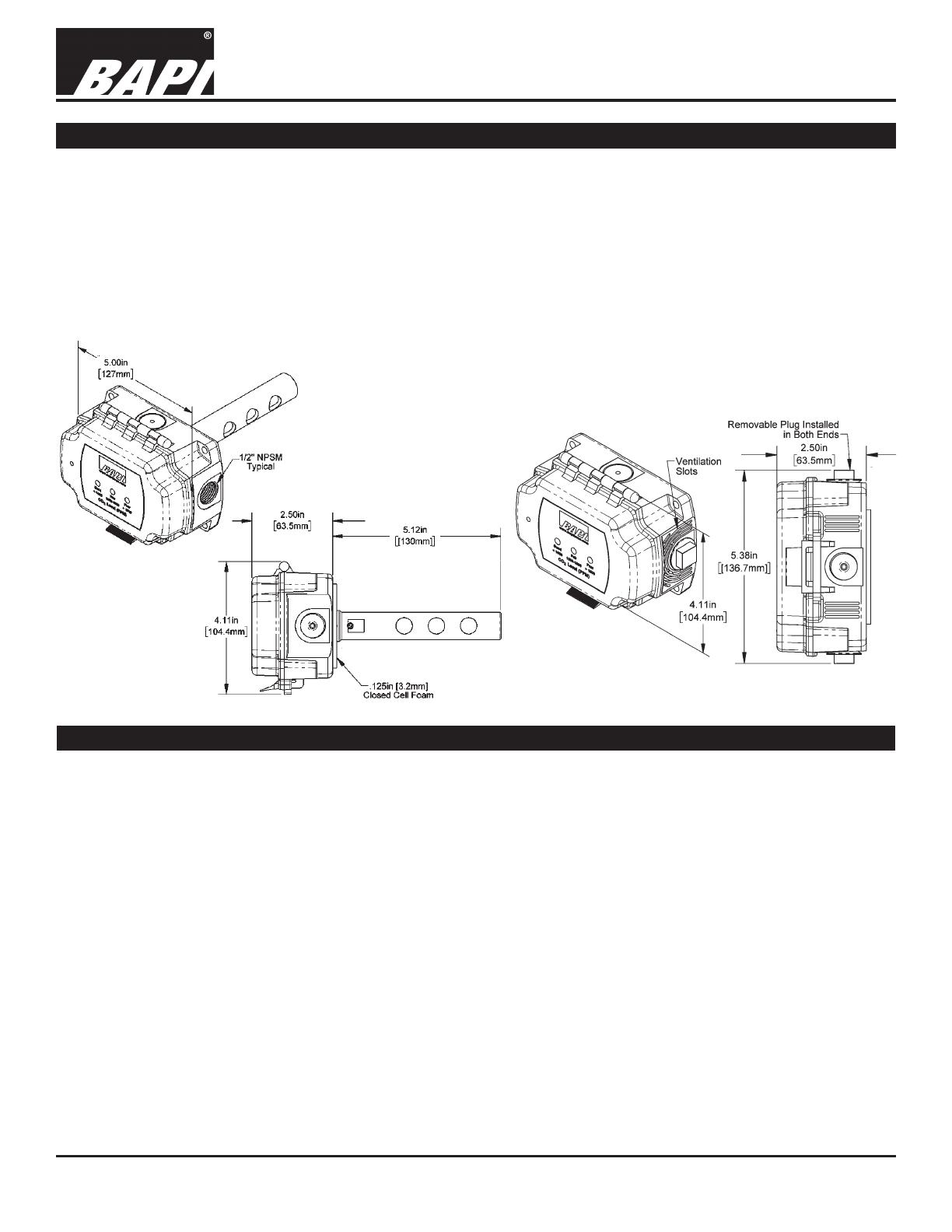
Identication and Overview
Fig. 1: Duct CO2
Sensor
Fig. 2: Rough Service CO2 Sensor
Specications
Power:
12 to 24 VDC, 240 mA
18 to 24 VAC, 12 VA Peak
Field Selectable Voltage Output:
0 to 5 or 0 to 10 VDC
Termination: 3 Terminals, 16 to 22 AWG
Operating Environment:
32 to 122°F (0 to 50°C)
0 to 95%RH non-condensing
Enclosure Rating:
Unventilated BAPI-Box: NEMA 4, IP66
Encl. Material: Polycarbonate, UL94 V-O
CO2 Detection PPM Range:
0 to 2,000, 0 to 5,000, 0 to 10,000 and 0 to 50,000
Start-Up Time: <2 Minutes
Response Time:
<2 Minutes for 90% step change typical (after start-up)
LED CO2 Level Indicator
(0 to 2,000 PPM units only):
Good, Green < 1,000 PPM
Fair, Yellow = 1,000 to 1,500 PPM
Poor, Red > 1,500 PPM
CO2 Sensing Elements:
Dual Channel Non-Dispersive Infrared
CO2 Drift Stability:
<5% of full scale over life of product.
CO2 Accuracy:
400 to 1,000 ppm: ±75 ppm
>1,000 ppm: ±10% of reading
Certications: RoHS
Warranty Period: 5 Years


