BAPI BA/ZPM-LR-NT-D-BB Low Range ZPM – Zone Pressure Sensor in a -Box Enclosure User manual

Type
User manual
Low Range ZPM - Zone Pressure Sensor
in a BAPI-Box Enclosure
Building Automation Products, Inc., 750 North Royal Avenue, Gays Mills, WI 54631 USA
Tel:+1-608-735-4800 • Fax+1-608-735-4804 • E-mail:[email protected] • Web:www.bapihvac.com 1 of 5
Installation & Operations
47139_ins_ZPM_LR_BB rev. 12/06/21
Fig 2: Setup
Switches for
Low Range
Units
1. Select OUTPUT
2. Select RANGE
If unit is ordered with a Custom Range,
then the switch must be set to R6.
3. Choose DIRECTION
Bidirectional is a plus/minus range so
choosing 1” range is -1” to +1” Bidirectional
and 0” to +1” Unidirectional
4. Choose UNITS - Inches WC or PASCALS
5. Choose RESPONSE TIME
Fast Response = 1/2 second
Slow Response = 4 seconds
6. Mount, Terminate and Auto-Zero the unit as
described in later sections.
Identication and Overview
BAPI’s ZPM is designed for quick
and easy eld installation. The
outputs, ranges, units, directionality,
and response time are all easily
set in the eld without powering the
unit.
The optional LCD display helps with
troubleshooting because it displays
the actual pressure regardless
of the selected pressure range.
Three LEDs on the face of the unit
indicate when the pressure is “Out
of Range Low”, “In Range” or “Out
of Range High” for the selected
range. The appropriate LED will
ash when out of range.
Switch Setup - Outputs, Ranges, Units/Response
Fig. 1: ZPM
BAPI-Box Unit and
Associated Parts
NOTE! Always follow the Auto-Zero procedure after changing settings.
Bulkhead tting
for static probe
Static probe
and tube
with surge
damper
(for units
ordered with
the included
static probe)
Cover latch
screws
Conduit
foam plug
Static probe
screws
Mounting
screws
Deadhead
tubing
Low Range ZPM - Zone Pressure Sensor
in a BAPI-Box Enclosure
Building Automation Products, Inc., 750 North Royal Avenue, Gays Mills, WI 54631 USA
Tel:+1-608-735-4800 • Fax+1-608-735-4804 • E-mail:[email protected] • Web:www.bapihvac.com 2 of 5
Installation & Operations
47139_ins_ZPM_LR_BB rev. 12/06/21
Attach the unit to its mounting surface with the four self-tapping #10x3/4”
sheet metal screws through the holes in the mounting feet. The preferred
mounting orientation is with the pressure ports facing down.
The two cover latch screws must be installed to achieve IP66 rating.
After Auto-Zeroing, remove the deadhead tubing and push the system
tubing onto the port nipple without creating any kinks or holes.
See page 3 for an actual size mounting template for the unit.
Fig. 3: ZPM BAPI-Box Mounting
(for units without Attached Tube
option)
Fig. 5: Cover
Latch Screws
Fig. 4: ZPM BAPI-Box Mounting
(for units with Attached Tube
option)
Mounting
Unit includes
two screws
for the hinged
cover
Low Range ZPM - Zone Pressure Sensor
in a BAPI-Box Enclosure
Building Automation Products, Inc., 750 North Royal Avenue, Gays Mills, WI 54631 USA
Tel:+1-608-735-4800 • Fax+1-608-735-4804 • E-mail:[email protected] • Web:www.bapihvac.com 3 of 5
Installation & Operations
47139_ins_ZPM_LR_BB rev. 12/06/21
Mounting Template
Fig. 6:
Mounting Hole Template - shown actual size
(BAPI recommends creating 5/32” (4mm) pilot holes
for the #10x3/4” self-tapping mounting screws.)
Center hole is
only needed for
the Attached
Static Probe
(-AT) version of
the ZPM unit
Low Range ZPM - Zone Pressure Sensor
in a BAPI-Box Enclosure
Building Automation Products, Inc., 750 North Royal Avenue, Gays Mills, WI 54631 USA
Tel:+1-608-735-4800 • Fax+1-608-735-4804 • E-mail:[email protected] • Web:www.bapihvac.com 4 of 5
Installation & Operations
47139_ins_ZPM_LR_BB rev. 12/06/21
AUTO-ZERO OPERATION
Auto-Zeroing must be done after the initial setup, changing mounting orientation or changing any settings. For most
applications, perform an auto-zero whenever it appears that the sensor has drifted. For critical applications, the unit
should be zeroed 2-3 times a year.
1. Power must be on.
2. Detach system tubing and deadhead ports using the supplied
tubing or other short length of tubing. Do not kink tubing.
3. Press and hold the Auto-Zero button for 1-2 seconds. The
Status LED will stop ashing when completed.
4. Remove deadhead tubing and reattach system tubing.
AUTO-ZERO OPERATION (Units w/ Attached Tube)
1. Power must be on.
2. Disconnect system tubing from the Low Pressure brass tting
and attach the supplied 6” deadhead tubing to the brass tting.
3.
Disconnect the short clear tubing from the 90° black Attached
Tube tting with your ngers (Fig. 9). A pliers may cut the tubing.
4. Connect the clear tubing to the supplied, straight black tting on the 6”
tubing (Fig. 9). Do not kink the tubing.
5. Press and hold the Auto-Zero button for 1-2 seconds. The Status LED
will stop ashing when completed.
6. Disconnect the deadhead tubing and reattach the clear tubing and
system tubing. Conrm that the clear tubing is pressed all of the way
onto the tting and that it is not kinked.
Fig 8: Auto-Zero and Status LEDs
Auto-Zero
LED
Status
LED
STATUS LED OPERATION
LED O: No power is applied or the unit is in 4 to 20 mA Mode
LED Solid (On): LED is on when power is applied and a VDC
output is selected. When 4 to 20 mA output is selected, the light is
on for 2 seconds at power up then goes o.
LED Flashing: Auto-Zero. The LED will ash for about 20 seconds.
Output Termination
BAPI recommends wiring the product with power disconnected.
Proper supply voltage, polarity and wiring connections are
important to a successful installation. Not observing these
recommendations may damage the product and void the warranty.
PWR
Terminal
GND
Terminal
OUT
Terminal
Fig. 7: ZPM Wiring Terminals
To ensure that all wires are properly terminated, twist the stripped ends of each
wire together before inserting into the terminals. Gently tug on the wire after
inserting into the terminal to verify a good connection.
Auto-Zero and Status LED Operation
Output Signal PWR Terminal GND Terminal OUT Terminal
4 to 20 mA 7 to 40 VDC 4 to 20 mA Signal To
Controller Analog Input Not Used
0 to 5 or 1 to 5 VDC 7 to 40 VDC
or 18 to 32 VAC To Controller Ground VDC Signal To Controller
Analog Input
0 to 10 or 2 to 10 VDC 13 to 40 VDC
or 18 to 32 VAC To Controller Ground VDC Signal To Controller
Analog Input
Table 1: ZPM Termination
Fig 9: Deadheading
ports on units with
attached tube (-AT)
Supplied
6” tubing
Supplied
straight
black tting
for dead-
heading
High
Port
Low
Port
Low Range ZPM - Zone Pressure Sensor
in a BAPI-Box Enclosure
Building Automation Products, Inc., 750 North Royal Avenue, Gays Mills, WI 54631 USA
Tel:+1-608-735-4800 • Fax+1-608-735-4804 • E-mail:[email protected] • Web:www.bapihvac.com 5 of 5
Installation & Operations
47139_ins_ZPM_LR_BB rev. 12/06/21
Specications subject to change without notice.
Selectable Low Ranges
Inches WC Pascals
0 to 0.10................................ 0 to 30
0 to 0.25................................ 0 to 50
0 to 0.50.............................. 0 to 100
0 to 0.75.............................. 0 to 175
0 to 1.00.............................. 0 to 250
-0.10 to 0.10 ...................... -30 to 30
-0.25 to 0.25 ...................... -50 to 50
-0.50 to 0.50 .................. -100 to 100
-0.75 to 0.75 .................. -175 to 175
-1.00 to 1.00 .................. -250 to 250
Diagnostics
POSSIBLE PROBLEMS:
Status LED does not light
Status LED is ashing
Output stuck (high or low)
Output not tracking pressure properly
POSSIBLE SOLUTIONS:
- Check power connections for proper power
- Sensor is set to 4 to 20mA output
- The unit is performing an auto-zero. Wait 20 seconds and check again.
- Remove pressure from ports and perform auto-zero procedure
- Check rotary switch for proper pressure range selection
- Check rotary switch for proper output range selection
Specications
Power:
7 to 40 VDC (4 to 20 mA Output)
7 to 40 VDC or 18 to 32 VAC (0 to 5 or 1 to 5 VDC Output)
13 to 40 VDC or 18 to 32 VAC (0 to 10 or 2 to 10 VDC Output)
Power Consumption:
20 mA max, DC only at 4 to 20 mA Output
5.2 mA max DC at 0 to 5 or 0 to 10 VDC Output
0.12 VA max AC at 0 to 5 or 0 to 10 VDC Output
Load Resistance:
4 to 20 mA Output 850 Ω Maximum @ 24 VDC
0 to 5 or 0 to 10 VDC Output 6KΩ Minimum
Accuracy: ±0.25% FS at 72°F (22°C) for All Units
Low Range: Proof 270” WC (67 kPa)
Stability: ±0.25% FS per year
Overpressure: Proof 270” WC (67 kPa)
Media: Clean, dry, non-corrosive gases
Compensated Temperature Range: 32 to 122°F (0 to 50°C)
Environmental Operating Range: -4 to 140°F (-20 to 60°C)
Storage Temperature: -40 to 185°F (-40 to 85°C)
Humidity: 0 to 95% RH, non-condensing
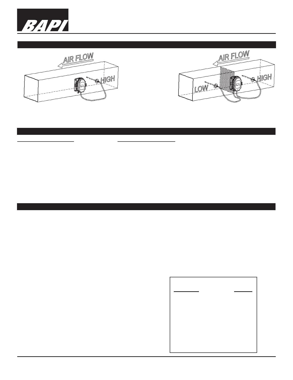
Typical Applications
NOTE: Best
practice is to
form a drip loop
in the tubing
to prevent
condensation
from reaching
the unit.
Fig. 10: Duct Static Pressure Monitoring
(ZPM Pressure Sensor mounted on the duct
with a Static Pressure Probe in the duct.)
Fig. 11: Air Filter Pressure Drop Monitoring
(ZPM Pressure Sensor mounted on the duct with a Static
Pressure Probe on either side of the lter in a duct.)
Wiring:
2 wires (4 to 20mA Current loop)
3 wires (AC or DC powered, VDC output)
Port Size: 1/4” barb
Enclosure Material:
UV-resistant Polycarbonate, UL94, V-0
Enclosure Rating: IP66, NEMA 4
Agency:
CE EN 61326-1:2013 EMC (Industrial
Electromagnetic Environment), UL, RoHS
  • Page 1 1
  • Page 2 2
  • Page 3 3
  • Page 4 4
  • Page 5 5

BAPI BA/ZPM-LR-NT-D-BB Low Range ZPM – Zone Pressure Sensor in a -Box Enclosure User manual

Type
User manual

Ask a question and I''ll find the answer in the document

Finding information in a document is now easier with AI