Page is loading ...

GALAXY® TR3 Gateway
Installation Manual
GXY-UM-00760-EN-01 (April 2015)

GALAXY® TR3 Gateway
Page ii April 2015GXY-UM-00760-EN-01

Installation Manual
CONTENTS
OVERVIEW . . . . . . . . . . . . . . . . . . . . . . . . . . . . . . . . . . . . . . . . . . . . . . . . . . . . . . . . . . . . . . . . . . . . . . . . . .5
Product Description . . . . . . . . . . . . . . . . . . . . . . . . . . . . . . . . . . . . . . . . . . . . . . . . . . . . . . . . . . . . . . . . . .5
License Requirements. . . . . . . . . . . . . . . . . . . . . . . . . . . . . . . . . . . . . . . . . . . . . . . . . . . . . . . . . . . . . . . . .5
Product Unpacking and Inspection . . . . . . . . . . . . . . . . . . . . . . . . . . . . . . . . . . . . . . . . . . . . . . . . . . . . . . . .5
SPECIFICATIONS . . . . . . . . . . . . . . . . . . . . . . . . . . . . . . . . . . . . . . . . . . . . . . . . . . . . . . . . . . . . . . . . . . . . . .6
Assembly Size, Weight, Wind Loading . . . . . . . . . . . . . . . . . . . . . . . . . . . . . . . . . . . . . . . . . . . . . . . . . . . . . .6
REPLACEMENT INSTALLATION . . . . . . . . . . . . . . . . . . . . . . . . . . . . . . . . . . . . . . . . . . . . . . . . . . . . . . . . . . . . .7
Cable and Power Supply . . . . . . . . . . . . . . . . . . . . . . . . . . . . . . . . . . . . . . . . . . . . . . . . . . . . . . . . . . . . . . .7
STANDARD COMPONENTS . . . . . . . . . . . . . . . . . . . . . . . . . . . . . . . . . . . . . . . . . . . . . . . . . . . . . . . . . . . . . . .8
Installation Tools and Materials (Customer-supplied) . . . . . . . . . . . . . . . . . . . . . . . . . . . . . . . . . . . . . . . . . . . . .8
ANTENNAS . . . . . . . . . . . . . . . . . . . . . . . . . . . . . . . . . . . . . . . . . . . . . . . . . . . . . . . . . . . . . . . . . . . . . . . . .9
Attach the Backhaul Antenna (CDMA) . . . . . . . . . . . . . . . . . . . . . . . . . . . . . . . . . . . . . . . . . . . . . . . . . . . . . .9
MOUNTING HARDWARE . . . . . . . . . . . . . . . . . . . . . . . . . . . . . . . . . . . . . . . . . . . . . . . . . . . . . . . . . . . . . . . .10
Gateway Backplate with Brackets . . . . . . . . . . . . . . . . . . . . . . . . . . . . . . . . . . . . . . . . . . . . . . . . . . . . . . . . 10
MOUNTING THE GATEWAY . . . . . . . . . . . . . . . . . . . . . . . . . . . . . . . . . . . . . . . . . . . . . . . . . . . . . . . . . . . . . . 13
Gateway Location . . . . . . . . . . . . . . . . . . . . . . . . . . . . . . . . . . . . . . . . . . . . . . . . . . . . . . . . . . . . . . . . . . 13
Using V-block Mounting Clamps . . . . . . . . . . . . . . . . . . . . . . . . . . . . . . . . . . . . . . . . . . . . . . . . . . . . . . . . . 14
Banding Mounting. . . . . . . . . . . . . . . . . . . . . . . . . . . . . . . . . . . . . . . . . . . . . . . . . . . . . . . . . . . . . . . . . .16
POWER SOURCE CONFIGURATIONS . . . . . . . . . . . . . . . . . . . . . . . . . . . . . . . . . . . . . . . . . . . . . . . . . . . . . . . . 17
Access to Power . . . . . . . . . . . . . . . . . . . . . . . . . . . . . . . . . . . . . . . . . . . . . . . . . . . . . . . . . . . . . . . . . . . 17
Use of a NEMA 4 Enclosure . . . . . . . . . . . . . . . . . . . . . . . . . . . . . . . . . . . . . . . . . . . . . . . . . . . . . . . . . . . . 17
Recommended Installation Congurations . . . . . . . . . . . . . . . . . . . . . . . . . . . . . . . . . . . . . . . . . . . . . . . . . . 17
CDMA or LAN with 120V AC Power Source. . . . . . . . . . . . . . . . . . . . . . . . . . . . . . . . . . . . . . . . . . . . . . . . . . .18
CDMA or LAN with DC Power Source . . . . . . . . . . . . . . . . . . . . . . . . . . . . . . . . . . . . . . . . . . . . . . . . . . . . . . 20
LAN with Power Over Ethernet (PoE) Power Source . . . . . . . . . . . . . . . . . . . . . . . . . . . . . . . . . . . . . . . . . . . . . 22
ELECTRICAL CONNECTIONS . . . . . . . . . . . . . . . . . . . . . . . . . . . . . . . . . . . . . . . . . . . . . . . . . . . . . . . . . . . . . 23
M12 Connector Assembly . . . . . . . . . . . . . . . . . . . . . . . . . . . . . . . . . . . . . . . . . . . . . . . . . . . . . . . . . . . . . 23
AC Power. . . . . . . . . . . . . . . . . . . . . . . . . . . . . . . . . . . . . . . . . . . . . . . . . . . . . . . . . . . . . . . . . . . . . . . .27
Lightning Arrestors . . . . . . . . . . . . . . . . . . . . . . . . . . . . . . . . . . . . . . . . . . . . . . . . . . . . . . . . . . . . . . . . . 27
RJ45 Plug Assembly for LAN Connectivity . . . . . . . . . . . . . . . . . . . . . . . . . . . . . . . . . . . . . . . . . . . . . . . . . . . 28
WEATHERPROOFING FOR CONNECTOR/CABLE CONNECTIONS . . . . . . . . . . . . . . . . . . . . . . . . . . . . . . . . . . . . . . 31
DUAL BACKHAUL CONFIGURATION . . . . . . . . . . . . . . . . . . . . . . . . . . . . . . . . . . . . . . . . . . . . . . . . . . . . . . . . 31
PROGRAMMING THE GATEWAY . . . . . . . . . . . . . . . . . . . . . . . . . . . . . . . . . . . . . . . . . . . . . . . . . . . . . . . . . . . 31
Page iii April 2015 GXY-UM-00760-EN-01

GALAXY® TR3 Gateway
Page iv April 2015GXY-UM-00760-EN-01

Overview
OVERVIEW
This manual provides installation instructions for the GALAXY® TR3 gateway receiver.
Proper performance and reliability depends upon installation in accordance with these instructions.
OTE:N Refer to the Gateway Configuration Software manual available at www.badgermeter.com for instructions on
configuring and programming the gateway.
Product Description
The GALAXY TR3 gateway receiver (“gateway”) is an easy-to-install, easy-to-deploy unit that collects metering data from the
GALAXY TR3 meter endpoints in the area.
The gateway uses a cellular or LAN network backhaul to forward metering data to the utility where the data can be used
to better manage the utility's operation and provide important data for improved customer service and utility operations.
The reading data management software (RDMS) manages this data transfer process and includes many tools and standard
reports, as well as the ability to create user-defined reports.
License Requirements
This device complies with Part 15, section 247 as an unlicensed transmitter and as a Part 15 unintentional radiator.
This device complies with Part 15 of the FCC rules. Operation is subject to the following two conditions: (1) This device may
not cause harmful interference, and (2) this device must accept any interference received, including interference that may
cause undesired operation.
In accordance with FCC regulations, “Code of Federal Regulations” Title 47, Part 2, Subpart J, Section 1091, transmitters pass
the requirements pertaining to RF radiation exposure. However, to avoid public exposure in excess of limits for general
population (uncontrolled exposure), a 20-centimeter distance between the transmitter and the body of the user must be
maintained during operation.
An FCC license is required to operate a GALAXY meter reading system.
This device complies with Industry Canada license-exempt RSS standard(s). Operation is subject to the following two
conditions: (1) this device may not cause interference, and (2) this device must accept any interference, including interference
that may cause undesired operation of the device.
Le présent appareil est conforme aux CNR d'Industrie Canada applicables aux appareils radio exempts de licence.
L'exploitation est autorisée aux deux conditions suivantes : (1) l'appareil ne doit pas produire de brouillage, et (2) l'utilisateur
de l'appareil doit accepter tout brouillage radioélectrique subi, même si le brouillage est susceptible d'en compromettre
le fonctionnement.
MPORTANTI
Changes or modifications to the equipment that are not expressly approved by Badger Meter could void the user’s authority to
operate the equipment. Only properly trained and authorized personnel should install and/or maintain this equipment.
Product Unpacking and Inspection
Upon opening the shipping container, visually inspect the product and applicable accessories for any physical damage such
as scratches, loose or broken parts, or any other sign of damage that may have occurred during shipment.
OTE:N If damage is found, request an inspection by the carrier’s agent within 48 hours of delivery and file a claim with the
carrier. A claim for equipment damage in transit is the sole responsibility of the purchaser.
Page 5 April 2015 GXY-UM-00760-EN-01

Specications
SPECIFICATIONS
Make sure to consider these specifications in your evaluation of an installation location.
MPORTANTI
The GALAXY TR3 gateway is functionally equivalent to the previous GALAXY gateway. However, the physical configuration of the
new enclosure is different. This change affects installation considerations, including cabling, size, weight and wind load area.
Installation 1.25…2.5" outside diameter pole mount: Aluminum V-blocks
2.5…24" outside diameter pole mount: BAND-IT® mounting bands
Size Height: 27" (includes antennas)
Width: 36"
Depth: 7.3" (includes V-block mounting)
Weight 16.3 lb
Enclosure Sealed, metallized fiberglass reinforced polyester (FRP) enclosure
Color Silver/gray
Operating Temperature –30…60° C (–22…140° F)
Storage Temperature – 40…85° C (– 40…185° F)
Backhaul Options CDMA with LAN
LAN with power
LAN with PoE
Power Supply DC voltage, 24V DC (AC adapter provided)
PoE alternative available for LAN
Solar can be used provided it meets DC requirements
Wind Loading Area 1.5 ft
2
Programming Locally: via programming harness
Assembly Size, Weight, Wind Loading
Height Width Depth Weight
Wind Loading
Area
Gateway Assembly Assembly includes gateway enclosure,
TX/RX antennas, backhaul antenna and
V-block mounting
27" 36" 7.3" 18 lb 1.5 ft
2
Mounting Hardware
V-block mounting kit 1.6 lb
Banding mounting kit 1.0 lb
Page 6 April 2015
GXY-UM-00760-EN-01

Replacement Installation
REPLACEMENT INSTALLATION
If you are replacing an existing GALAXY gateway, review the following information before starting installation. You may be
able to re-use the existing cable and power supply.
Cable and Power Supply
Existing Power Supply TR3 Gateway Power Supply
Gray power cable with 12V power
supply (Figure 1)
Replace cable and power supply with the new power/communication cable
provided with the GALAXY TR3 gateway. See "Chart A: WIRING THE GATEWAY WITH
NEW POWER/COMMUNICATION CABLE" on page 24.
15V DC power supply with
308 connector (Figure 2) or
customer-supplied DC power source
(see "CDMA or LAN with DC Power
Source" on page 20)
You can re-use the existing cable and power supply but you must wire the M12
connector for the GALAXY TR3 gateway using the wiring diagram provided. See
"Chart B: WIRING THE GATEWAY RE-USING THE GALAXY 3.0/3.3 GATEWAY POWER/
COMMUNICATION CABLE" on page 24.
OTE:N The black cable does not wire directly to the board.
Existing gateway connects via LAN Replace the adapter with an ethernet cable. You cannot re-use the serial-to-LAN
adapter (Figure 3) for the GALAXY TR3 gateway receiver. See "RJ45 Plug Assembly for
LAN Connectivity" on page 28.
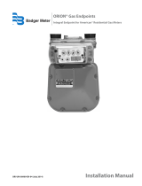
Figure 1: Gray power cable and 12V power supply Figure 2: Black cable and 24V power supply
Figure 3: Serial-to-LAN adapter
Page 7 April 2015 GXY-UM-00760-EN-01

Standard Components
STANDARD COMPONENTS
• One gateway receiver with attached mounting backplate and antenna(s).
• V-block clamps or banding and locking equipment for attaching the gateway to a pole.
• 100-foot or 300-foot power/communication cable, M12 connector, AC-to-DC power supply and power cord.
Figure 4: GALAXY TR3 gateway components
FAILURE TO READ AND FOLLOW THE INSTRUCTIONS IN THIS MANUAL CAN LEAD TO MISAPPLICATION OR
MISUSE OF THE GALAXY GATEWAY RECEIVER, RESULTING IN PERSONAL INJURY AND DAMAGE TO THE EQUIPMENT.
Installation Tools and Materials (Customer-supplied)
• Phillips #2 screwdriver
• Precision slotted screwdriver with a 2.0 millimeter (0.079 inch) blade size
• Two 9/16 inch or adjustable wrenches for mounting V-block clamps (standard mounting)
• BAND-IT® tool (see "Banding Mounting" on page 16) and instructions, 1/2 inch wrench and a hammer for large
diameter pole mounting, if required
• Wrench (for 1-1/16 inch gland nut and 1-1/16 inch dome nut)
• Pliers or strap wrench (for tightening the 15/16 inch OD backhaul antenna and other Type N connectors)
• 7/16 inch socket wrench for all other bolts and nuts
• Cat5e Ethernet cable (outdoor-rated) and RJ45 jack for LAN connection
Backhaul Antenna
Included for CDMA
Configuration
Page 8 April 2015GXY-UM-00760-EN-01

Antennas
ANTENNAS
The gateway ships in a direct mount configuration with the TX/RX antennas attached.
Attach the Backhaul Antenna
1. Remove the plastic cover from the Type N female connector on the backhaul antenna bracket.
2. Remove the backhaul antenna from the carton.
3. Thread the Type N male connector (antenna) onto the Type N female connector on the backhaul antenna bracket.
OTE:N See"Backhaul Antenna Bracket" on page 12 for additional mounting information.
4. Hand tighten until nger tight. Then use pliers or a strap wrench to tighten an additional 1/16 inch turn (maximum).
Do not over-tighten or the connector can be damaged.
Page 9 April 2015 GXY-UM-00760-EN-01

Mounting Hardware
MOUNTING HARDWARE
Gateway Backplate with Brackets
The backplate of the gateway receiver has a modular design consisting of three brackets—the TX/RX antenna bracket,
mounting bracket and backhaul antenna bracket—joined together. When shipped, the three brackets are attached as shown
in Figure 5. Together they make up the gateway backplate, which is attached to the gateway enclosure bracket. The brackets
can be separated to provide additional mounting options. A description of each bracket starts on the next page.
Figure 5: Gateway backplate
The gateway enclosure is permanently mounted to the enclosure bracket which is used to attach the gateway to the
backplate. When shipped, the gateway enclosure bracket is attached securely to the backplate.
Figure 6: Gateway receiver enclosure with enclosure bracket
Mounting Bracket
Backhaul Antenna
Bracket
TX/RX Antenna
Bracket
Gateway Enclosure
Enclosure Bracket
Page 10 April 2015GXY-UM-00760-EN-01

Mounting Hardware
Mounting Bracket
Machined with multiple holes to accommodate different mounting options, the mounting bracket is the largest part of the
gateway backplate. Mounting holes are labeled for V-block, banding and wall mounting options. The bracket also has 1/4 inch
and 3/8 inch grounding points (see Figure 7) which can be used if needed.
Figure 7: Mounting bracket
Mounting Options
The circular hole pattern on the mounting bracket can be used to accommodate mounting the gateway on an angled beam
or pole, if necessary.
The gateway can also be mounted on a wall. The mounting bracket has four 0.28 inch holes marked for this option.
OTE:N For a wall mount, customers must supply the mounting hardware suitable for the substructure on which the gateway
is mounted.
For mounting options, all gateway installation considerations must be observed. See "Specifications" on page 6 and
"Installation Tools and Materials (Customer-supplied)" on page 8.
TX/RX Antenna Bracket
The TX/RX antenna bracket is used for
mounting the TX/RX antenna. When shipped,
the TX/RX antenna bracket is attached to
the top of the mounting bracket with three
locknuts using the holes indicated in Figure 8.
Other holes on the bracket can be used to
accommodate a variety of mounting options.
Figure 8: TX/RX antenna bracket
Used to Mount Backhaul
Antenna Bracket
Used to Mount TX/RX
Antenna Bracket
Grounding Points
Page 11 April 2015 GXY-UM-00760-EN-01

Mounting Hardware
Backhaul Antenna Bracket
The backhaul antenna bracket is used for
mounting the backhaul antenna. When
shipped, the backhaul antenna bracket is
attached to the bottom of the mounting
bracket with two locknuts (PN: 67810-001)
using the holes indicated in Figure 9.
Other holes on the bracket can be
used to accommodate a variety of
mounting options.
A backhaul antenna can be connected
to the mounting bracket with either end
up. However, the antenna must always be
connected at the narrow end, hanging away
from the bracket as shown in Figure 10.
Figure 9: Backhaul antenna bracket
Correct Antenna Mount Correct Antenna Mount Incorrect Antenna Mount
Figure 10: Backhaul antenna mounting
Page 12 April 2015GXY-UM-00760-EN-01
X

Mounting the Gateway
MOUNTING THE GATEWAY
MPORTANTI
Receiver installation, mounting and disposal shall be in accordance with all local, state and federal regulations. When installing
the receiver, customer is responsible for complying with local, state, and federal codes and guidelines, as well as applicable industry
standards, such as ANSI/TIA/EIA 222 (structural standards for steel antenna towers and antenna supporting structures) and the
National Electrical Code (NEC). Proper grounding is necessary, and in the case of a wooden pole, a dedicated copper ground wire
should be used for lightning protection.
Gateway Location
The utility is responsible for properly positioning the gateway. For optimal reception and transmission, locate the gateway
and antennas in line-of-sight view of the desired endpoints.
To help maximize the performance of your GALAXY fixed network system, the following installation guidelines and
recommendations should be considered when selecting mounting locations for the gateway.
• Avoid installing the gateway next to or between objects such as tall buildings, towers, bridges, highway overpasses
or signs that obstruct the line of sight with the endpoints.
• Avoid installing the gateway near RF transmitters or other sources of RF radiation including high-power in band and
near-power sources such as pagers, cellular 900 MHz transmitters and communications transmitters. Other potential
sources of RF radiation include power line transformers, neon or fluorescent signs, RADAR transmitters and SCADA
systems. If the gateway is to be located near other RF radiators, a minimum distance of 100 feet horizontal separation
and 10 feet vertical separation must be maintained between the gateway and the source of RF radiation.
• Avoid installing the gateway antennas inside metal enclosures or inside of a building as the antennas cannot
communicate if surrounded by metal.
• Mount the gateway as high as possible above average terrain, within the limits of the 300-foot power cable, and
maintain a 30 degree view of the horizon.
• Minimum standoff distance of 2 feet from any structure is required.
• Position the gateway no closer than 25 feet from the nearest endpoint.
Page 13 April 2015 GXY-UM-00760-EN-01

Mounting the Gateway
Using V-block Mounting Clamps
The V-block mounting clamps are sized for mounting the gateway on a vertical or horizontal pole with outer diameters
ranging from 1-1/4… 2-1/2 inches. For mounting on poles larger than 2-1/2 inches, see "Banding Mounting" on page 16.
1. Open the bag of mounting equipment.
2. Place two bolts (3/8-16 x 5 inches) through the holes in the top of the gateway mounting backplate (Figure 11). Use
the backplate circular pattern holes for horizontal installation.
3. Place a clamp onto the bolts, as shown below.
4. Place a lock washer and nut onto each bolt, as shown below.
OTE:N The lock washer and nut nearest the enclosure mounting bracket can be omitted when mounting on smaller
diameter poles to provide additional clamping distance.
Figure 11: Mounting clamp at top of the backplate
5. Tighten the two nuts with a 9/16 inch or adjustable wrench so that each lock washer is fully compressed and at.
6. Repeat steps 2 through 5, attaching a clamp to the bottom of the gateway mounting backplate. Position the gateway
on the pole and place a clamp on the top bolts.
Figure 12: Clamps with hardware
Bolts
Nuts
Lock Washers
Clamps
Page 14 April 2015GXY-UM-00760-EN-01

Mounting the Gateway
7. Place a lock washer and nut on each bolt and tighten the nuts 100…150 inch-pounds to ensure the gateway is
suciently secured to the pole.
8. Repeat steps 7 and 8 for attaching the V-block clamp mounting hardware to the bottom bolts of the
mounting backplate.
Side View
Back View
Side View
Figure 13: Completed gateway mounting
V-block mounting is complete.
Page 15 April 2015 GXY-UM-00760-EN-01

Mounting the Gateway
Banding Mounting
Banding mounting equipment is sized to mount the gateway on a 2-1/2…24 inch outer diameter pole.
OTE:N Installation of banding mounting requires the use of the BAND-IT tool (PN: 66042-006) or equivalent BAND-IT tool as
recommended by BAND-IT.
MPORTANTI
When using the banding mounting kit for the gateway, use BAND-IT Idex installation practices. Refer to
www.band-it-idex.com/en/Literature/Tool_Instructions/P05886.pdf for more information. This is especially applicable when
mounting on a non-tapered vertical pole, as the banding could loosen over time resulting in the unit sliding down the pole.
Figure 14: Banding and locking equipment Figure 15: BAND-IT tool
1. To mount the gateway on a pole, gather the banding and locking equipment.
2. Locate the BAND-IT tool and supplied installation instructions.
3. Follow the installation instructions enclosed with the BAND-IT tool for attaching the gateway receiver to a pole.
4. Using a 1/2 inch wrench, apply the recommended torque for the 5/16-24 screw that attaches the gateway bracket to
the BAND-IT banding. The recommended torque is 144…168 inch-pounds (12…14 foot-pounds).
Figure 16: Gateway shown with BAND-IT mounting hardware
Banding mounting is complete.
Page 16 April 2015GXY-UM-00760-EN-01

Power Source Congurations
POWER SOURCE CONFIGURATIONS
Access to Power
• The gateway receiver requires access to power. The gateway can use a 120V AC grounded outlet for use with the
AC-to-DC power supply and power cord (PN: 66528-003), or a DC power source for use with the DC power source
cable with 308 in-line connector (PN: 66233-020). For a gateway with a LAN PoE configuration, a Power over Ethernet
connection is required. Diagrams of each power source configuration start on page 18.
• Outlet and enclosure (if required) should be mounted for easy accessibility by authorized utility personnel at the
installation site.
• Consult the appropriate electrical, building and industry codes, regulations and standards for accepted installation
practices for use of the AC-to-DC power supply and outlet in environmentally controlled indoor locations.
Use of a NEMA 4 Enclosure
AC-to-DC power supply used outdoors or in a non-environmentally controlled indoor location requires a customer-supplied
NEMA 4 enclosure, or equivalent, installed in accordance with appropriate electrical codes, building codes, industry codes,
regulations and standards.
Recommended Installation Congurations
These are the standard recommended installation configurations with various combinations of backhaul and power source:
• CDMA with 120V AC power source
• LAN with 120V AC power source
• CDMA with DC power source
• LAN with DC power source
• LAN with PoE power source
Diagrams of the above configurations are shown on the pages that follow. Consult the appropriate diagram for your
installation configuration.
Page 17 April 2015 GXY-UM-00760-EN-01

Power Source Congurations
CDMA or LAN with 120V AC Power Source
Configurations for a 120V AC grounded outlet with CDMA and LAN are shown here.
CDMA Connection with 120V AC Power Source
AC to DC Power Supply with
308 In-line Connector End and
Power Cord (supplied)
120VAC
Grounded Outlet
(customer
supplied)
Power Supply Cable with
308 In-line Connector
ORION SE Power Cable with
308 In-line Connector
(supplied)
Figure 17: CDMA connection with AC power source (*Shown with NEMA 4 enclosure)
*An enclosure may be recommended but is not included. If NEMA 4 enclosure or equivalent is required, as in an outdoor
installation, the minimum enclosure size is 12 inch x 10 inch x 6 inch (H x W x D).
Page 18 April 2015GXY-UM-00760-EN-01

Power Source Congurations
LAN with 120V AC Power Source
OTE:N Consult the manufacturer's installation and usage recommendations as well as appropriate codes, regulations and
standards for the LAN RJ45 Ethernet connection.
AC to DC Power Supply with 308
In-line Connector End and Power Cord
(supplied)
120VAC
Grounded Outlet
(customer
supplied)
To Utility
Network
Outdoor-rated
CAT5e Ethernet
Cable (customer
supplied)
LAN RJ45 Ethernet
Connection
(customer supplied)
Power Supply Cable with
308 In-line Connector
ORION SE Power Cable with
308 In-line Connector
(supplied)
Figure 18: LAN connection with AC power source (*Shown with NEMA 4 enclosure)
*An enclosure may be recommended but is not included. If NEMA 4 enclosure or equivalent is required, as in an outdoor
installation, the minimum enclosure size is 12 inch x 10 inch x 6 inch (H x W x D).
Page 19 April 2015 GXY-UM-00760-EN-01

Power Source Congurations
CDMA or LAN with DC Power Source
The gateway receiver can be ordered with a 10-foot DC power source cable (PN: 66233-020) for direct connection with a
customer-supplied DC power source. The gateway requires about 6W average power and 12W peak power. When connecting
an AC-to-DC power supply, use a power supply rated at 1A (minimum) at 24V DC.
OTE:N Consult the appropriate electrical, building and industry codes, regulations and standards for accepted installation
practices when attaching the cable to a DC power source.
Figure 19: 10' DC power cable
Absolute Requirements
The gateway can be powered by a DC voltage source between 12…30V. Cable length must be reduced to 100 feet, or less, if
less than a 24V source is being used. For reference, when connecting directly to batteries, as in a solar assembly (not supplied),
the average electrical load is 12V DC at 0.5A continuous. Cables, fuses and/or circuit breakers MUST be capable of handling at
least 1A peak currents.
External DC Power Source Connections
Wire Color for PN: 66233-020 External DC Power Source
Drain (no insulation) Negative (–)
Black Negative (–)
Brown Negative (–)
Red Positive (+)
Blue Positive (+)
Page 20 April 2015GXY-UM-00760-EN-01
/