CTC Union FMUX800 User manual

Type
User manual

This manual is also suitable for

FMUX80/160/800/1600
Fiber Optical Multiplexer
Standalone / Rack Type
8/16 Channel E1/T1 plus 100M/1G Ethernet
SNMP Manageable
LEGAL
Theinformationinthispublicationhasbeencarefullycheckedandisbelievedtobeentirelyaccurateatthetimeof
publication.CTCUnionTechnologiesassumesnoresponsibility,however,forpossibleerrorsoromissions,orforany
consequencesresultingfromtheuseoftheinformationcontainedherein.CTCUnionTechnologiesres
ervestheright
tomakechangesinitsproductsorproductspecificationswiththeintenttoimprovefunctionordesignatanytime
andwithoutnoticeandisnotrequiredtoupdatethisdocumentationtoreflectsuchchanges.
CTCUnionTechnologiesmakesnowarranty,representation,orguaranteeregardingthesuitabilityofitsprod
uctsfor
anyparticularpurpose,nordoesCTCUnionassumeanyliabilityarisingoutoftheapplicationoruseofanyproduct
andspecificallydisclaimsanyandallliability,includingwithoutlimitationanyconsequentialorincidentaldamages.
CTCUnionproductsarenotdesigned,intended,orauthorizedforuseinsy
stemsorapplicationsintendedtosupport
orsustainlife,orforanyotherapplicationinwhichthefailureoftheproductcouldcreateasituationwherepersonal
injuryordeathmayoccur.ShouldtheBuyerpurchaseoruseaCTCUnionproductforanysuchunintendedor
unauthorizedapplication,theBu
yershallindemnifyandholdCTCUnionTechnologiesanditsofficers,employees,
subsidiaries,affiliates,anddistributorsharmlessagainstallclaims,costs,damages,expenses,andreasonableattorney
feesarisingoutof,eitherdirectlyorindirectly,anyclaimofpersonalinjuryordeaththatmaybeassociatedwithsuch
unintendedorunauthorizeduse,evenifsuchclaimallegesthatCTCUn
ionTechnologieswasnegligentregardingthe
designormanufactureofsaidproduct.
TRADEMARKS
MicrosoftisaregisteredtrademarkofMicrosoftCorp.
HyperTerminal™isaregisteredtrademarkofHilgraeveInc.
WARNING:
ThisequipmenthasbeentestedandfoundtocomplywiththelimitsforaClassAdi
gitaldevice,pursuanttoPart15of
theFCCRules.Theselimitsaredesignedtoprovidereasonableprotectionagainstharmfulinterferencewhenthe
equipmentisoperatedinacommercialenvironment.Thisequipmentgenerates,uses,andcanradiateradio
frequencyenergyandifnotinstalledandusedinaccordancewiththei
nstructionmanualmaycauseharmful
interferenceinwhichcasetheuserwillberequiredtocorrecttheinterferenceathisownexpense.NOTICE:(1)The
changesormodificationsnotexpressivelyapprovedbythepartyresponsibleforcompliancecouldvoidtheuser's
authoritytooperatetheequipment.(2)Shieldedinterf
acecablesandACpowercord,ifany,mustbeusedinorderto
complywiththeemissionlimits.
CISPRPUB.22ClassACOMPLIANCE:
ThisdevicecomplieswithEMCdirectiveoftheEuropeanCommunityandmeetsorexceedsthefollowingtechnical
standard.EN55022‐LimitsandMethodsofMeasurementofRadioI
nterferenceCharacteristicsofInformation
TechnologyEquipment.ThisdevicecomplieswithCISPRClassA.
WARNING:
ThisisaClassAproduct.Inadomesticenvironmentthisproductmaycauseradiointerferenceinwhichcasetheuser
mayberequiredtotakeadequatemeasures.
CENOTICE
MarkingbythesymbolCEindicatescompli
anceofthisequipmenttotheEMCdirectiveoftheEuropeanCommunity.
Suchmarkingisindicativethatthis equipmentmeetsorexceedsthefollowingtechnicalstandards:EN
55022:2006+A1:2007,ClassA,EN55024:2010,andEN609501:2006
CTC Union Technologies Co., Ltd.
Far Eastern Vienna Technology Center (Neihu Technology Park)
8F, No. 60, Zhouzi St.
Neihu, Taipei, 114
Taiwan
Phone: +886-2-2659-1021
FAX: +886-2-2799-1355
FMUX160/80/1600/800
Fibermultiplexerwith8/16channelsE1/T1and100M/1GEthernetTrunk.
InstallationandOperationManual
Version1.0April10,2014(Release)
Thisdocumentsupportsthefollowingmodels:
FMUX80B8Ch.UnbalancedE1,BNCwith4portEthernetSwitchand100MEthernetwirespeedtrunk
FMUX80R8Ch.BalancedE1
/T1,RJ45with4portEthernetSwitchand100MEthernetwirespeedtrunk
FMUX160B16Ch.UnbalancedE1,BNCwith4portEthernetSwitchand100MEthernetwirespeedtrunk
FMUX160R16Ch.BalancedE1/T1,RJ45with4portEthernetSwitchand100MEthernetwirespeedtrunk
FMUX800B8Ch.U
nbalancedE1,BNCwith4portGigabitEthernetSwitchand850MEthernettrunk
FMUX800R8Ch.BalancedE1/T1,RJ45with4portGigabitEthernetSwitchand850MEthernettrunk
FMUX1600B16Ch.UnbalancedE1,BNCwith4portGigabitEthernetSwitchand850MEthernettrunk
FMUX1600R16Ch.Balan
cedE1/T1,RJ45with4portGigabitEthernetSwitchand850MEthernettrunk
Thisdocumentisthecurrentofficialreleasemanual.PleasecheckCTCUnion'swebsiteforanyupdatedmanualor
contactusbyEmailattechsupport@ctcu.com.Pleaseaddressanycommentsforimprovingthismanualortopoint
outomissionsorerrorstom
[email protected].Thankyou.
©2013~2014CTCUnionTechnologiesCo.,Ltd.
AllRightsReserved
Thecontentsofthisdocumentaresubjecttochangewithoutanypriornotice.
Table of Contents
i
CHAPTER1.IN
TRODUCTION .................................................................................................................................... 7
1.1GENERAL ......................................................................................................................................................................7
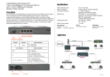
1.2FUNCTIONALDESCRIPTION ...............................................................................................................................................7
1.3TECHNICALSPECIFICATIONS............................................................................................................................................10
1.4E1SIGNALSTRUCTURE..................................................................................................................................................13
1.5T1(DS1)SIGNALSTRUCTURE .........................................................................................................................................13
1.6APPLICATIONS/CAPABILITIES .........................................................................................................................................14
CHAPTER2.INSTALLATION .................................................................................................................................... 15
2.1GENERAL ....................................................................................................................................................................15
2.2SITEPREPARATION .......................................................................................................................................................15
2.3MECHANICALASSEMBLY................................................................................................................................................15
2.4ELECTRICALINSTALLATION..............................................................................................................................................16
2.4.1Powerconnection.............................................................................................................................................16
2.4.2RearandFrontpanelconnectors .....................................................................................................................17
2.5REMOVAL/REPLACEMENTPROCEDURES ...........................................................................................................................18
2.5.1SFPRemoval/Replacement(HotSwappable) .................................................................................................18
2.5.2TopcoverRemoval/Replacementforinternalaccess.....................................................................................19
2.5.3SNMPFeatureRemoval/Replacement ...........................................................................................................20
CHAPTER3.CONSOLEOPERATION ......................................................................................................................... 21
3.1INTRODUCTION ............................................................................................................................................................21
3.2TERMINALMODEOPERATION ........................................................................................................................................21
3.3CONNECTINGTOTHEFIBERMULTIPLEXER .........................................................................................................................22
3.4CONFIGURINGINCONSOLEMODE...................................................................................................................................23
3.4.1Login.................................................................................................................................................................23
3.4.2MainMenu.......................................................................................................................................................23
3.4.3DeviceConfigurationMenu..............................................................................................................................24
3.4.4PasswordConfigurationMenu.........................................................................................................................25
3.4.5AlarmConfigurationMenu...............................................................................................................................26
3.4.6OrderWire........................................................................................................................................................26
3.4.7StoreParameters..............................................................................................................................................27
3.4.8AggregateConfiguration..................................................................................................................................28
3.4.9OpticalLoopBack.............................................................................................................................................29
3.4.10E1/T1ModeConfiguration(RJ45modelsonly)..............................................................................................30
3.4.11E1(T1)Configuration .....................................................................................................................................30
3.4.12LANPortConfiguration ..................................................................................................................................32
CHAPTER4.WEBBASEDOPERATION ..................................................................................................................... 35
4.1GENERAL ....................................................................................................................................................................35
4.2TCP/IPCONFIGURATION...............................................................................................................................................35
4.3BROWSERLOGIN..........................................................................................................................................................35
4.3.1PanelDisplay ....................................................................................................................................................36
4.3.2Configuration ...................................................................................................................................................37
4.3.3TCP/IPConfiguration........................................................................................................................................38
4.3.4DateandTimeConfiguration ...........................................................................................................................38
4.3.5SNMPManagerConfiguration .........................................................................................................................39
4.3.6SYSLOGConfiguration ......................................................................................................................................40
4.3.7LOGInformation...............................................................................................................................................41
4.4PROVISIONINGVIAWEB ................................................................................................................................................42
4.4.1DeviceConfiguration........................................................................................................................................42
4.4.2OpticalConfiguration .......................................................................................................................................43
4.4.3E1/T1Configuration .........................................................................................................................................44
4.4.4LANConfiguration ............................................................................................................................................45
4.4.5OrderWireConfiguration.................................................................................................................................46
4.4.6SFPInformation................................................................................................................................................47
4.5REMOTEMANAGEMENT................................................................................................................................................48
Table of Contents
ii
CHAPTER5.SN
MPOPERATION ..............................................................................................................................48
5.1GENERAL ................................................................................................................................................................... 48
5.2SNMPOPERATIONS .................................................................................................................................................... 49
5.3THEMANAGEMENTINFORMATIONBASE ......................................................................................................................... 50
5.4MIBSTRUCTURE ......................................................................................................................................................... 50
5.5SNMPCOMMUNITIES ................................................................................................................................................. 50
5.6SNMPUPGRADEVIATFTP .......................................................................................................................................... 51
5.7SNMPTRAPMESSAGES ............................................................................................................................................... 52
Chapter 1. Introduction
7
Chapter 1. Introduction
1.1 General
ThankyouforchoosingFMUX80/160/FMUX800/1600.Ifyouwouldliketoskip right to the installation and
configurationoftheMultiplexer,proceedtoChapters3and4.
The Fiber Multiplexer is a 1U (1.75") high standalone or 19" rack mountable E1/T1/LAN multiplexer over
fiber link, built upon a cost effective fixed design. Th
e Fiber Multiplexer providesan economic optical connection
solution in highdensity E1 and/or T1 installations such as between branch offices or for 2G/3G mobile backhaul,
where multiple high speed synchronous data communications are required with highspeed Ethernet backhaul. By
utilizingafixeddesign,costsarereducedandreliabilityimproved.Thestandar
dunitisachassiswithlocalcontroland
ordered with single or dual power. One model supports RJ45 connectors for E1/T1, wired per USOC RJ48C, while
anothermodelboasts BNC connectorsforunbalanced75E1 over coaxial cables. TheFMUX160utilizesfixed optical
transceiversandconnectoroptionsincludingST™
,SCorFC.TheFMUX1600usesSFPcagesthatsupportanyindustry
standard1.25GbpsSFPmodule.Therangeof transmissionforopticalconnectionisfrom2Km(formultimode)upto
120Km (single mode). Optional SNMP Card (for local and remote management purposes) may be ordered and
installedinth
echassis.
1.2 Functional Description
TheFiber Multiplexer basicchassisisavailableinfivepowersupplyconfigurations.Dependingonthemodel,
powermaybederivedfromsingleAC100~240VAC,singleDC+18~60VDC,dualAC100~240VAC,dualDC+18~60VDC,
orACplusDCpowersources.TheFiber Multiplexer providesallE1/T1andLANconnectionsontherearpanel.The
frontpanelpr
ovidestheLEDindicators,orderwire,clearchannelRS232,aggregateopticalandconsoleconnectors.
ModelBreakdown:
FMUX80B8Ch.UnbalancedE1,BNCwith4portEthernetSwitchand100MEthernetwirespeedtrunk
FMUX80R8Ch.BalancedE1/T1,RJ45with4portEthernetSwitchand100MEthernetwirespeedtrunk
FMUX160B16Ch.UnbalancedE1,BNCwith4portEthernetSwitchand100MEthernetwirespeedtrunk
FMUX
160R16Ch.BalancedE1/T1,RJ45with4portEthernetSwitchand100MEthernetwirespeedtrunk
FMUX800B8Ch.UnbalancedE1,BNCwith4portGigabitEthernetSwitchand850MEthernettrunk
FMUX800R8Ch.BalancedE1/T1,RJ45with4portGigabitEthernetSwitchand850MEthernettrunk
FMUX
1600B16Ch.UnbalancedE1,BNCwith4portGigabitEthernetSwitchand850MEthernettrunk
FMUX1600R16Ch.BalancedE1/T1,RJ45with4portGigabitEthernetSwitchand850MEthernettrunk
The 16CHANNEL "B" Model has 16 pairs of BNC (75 Ohm unbalanced) connectors for E1 Line interface
con
nectionssupportingsixteenseparateE1channelsatatransmissionrateof2.048Mb/s(transparentunframedE1)
each.
The 16CHANNEL "R" Model provide 16 RJ45 (120/100 Ohm balanced, software selectable) connectors for
E1/T1(DS1) Line interface connections supporting sixteen separate E1/T1(DS1) channels at a transmission rate of
2.048/1.544Mb/s (transparent unframe
d E1/T1) each. E1 and T1 configuration cannot be mixed; all ports must be
eitherE1orT1.
The8CHANNELmodelshavethesamefeatures,butwithonly8tributarychannels.
ThebuiltinEthernetSwitchprovidesfourRJ45connectorsfor10/100MwirespeedEthernet(FMUX80/160)
or10
/100/1000MEthernet(FMUX800/1600up to850Mtrunk speed).Theswitchfunctionprovidesauto/forcedper
portsettings,PortbasedVLANandEthernetflowcontrolenable/disable.
LEDsonthefrontpanelwillshowpower,alarmandchannelstatusesforallports.
Chapter 1. Introduction
8
TheFiber Multiplexer E1andT1InterfacePortsfullymeetallE1andT1specificationsincludingITUTG.703,
G.704,G.706,G.732,G.733,G.823andG.824.TheEthernetswitchmeetsallEthernetspecificationsforIEEE802.3and
IEEE802.3u.
EachE1/T1CHANNELPortfeaturesdiagnosticcapabilitiesforperforminglocalloopbackorremoteloopbac
k.
The loop back function is controlled by the terminal mode (RS232 console) or when the SNMP option board is
installedviaTelnet,WeborSNMPsetcommands.
Theunitoperatesfromaninternalfreerunningoscillator.TheFiber Multiplexer iscompletelytransparentto
clockinganddatatransmission.ThismakesconfigurationoftheMU
Xextremelyeasy.
Whenthe Fiber Multiplexer isordered with an optionalSNMP Module, themodule card is installed inside
thechassis.ConfigurationisaccomplishedvialocalcontrolontheasynchronousRS232portwith astandardVT100
terminal,viaEthernetandTelnet,orviaanystandardSNMPnetworkmanagementsoftwareoverEth
ernet.TheFiber
Multiplexerwill then also have an embeddedweb server to provide local or remote management using any www
browser. If the SNMP Card option is not installed, local management is still possible via the unit's internal menu
systemaccessiblefromtheasynchronousRS232portwithastandardVT10
0terminal.
TheFiber Multiplexer alsoincludesthe ability todoinbandremoteconfiguration.Oncethefiberopticli nk
has been established, the remote unit may be configured or status checked from the local unit using any of the
availablemanagementoptions.
Chapter 1. Introduction
9
Thefollowingphoto,withgraphics,showsthemajorcomponentswhichmakeuptheFiber Multiplexer (with
theSNMPoptioninstalled).Thisphotoshowsaunitwith16E1/T1RJ45interfaces.
Figure11:Fiber Multiplexer MajorComponents
DC
AC
SFP
SNMP
Chapter 1. Introduction
10
1.3 Technical Specifications
E1Link
Framing Unframed (transparent)
Bit Rate 2.048 Mb/s
Line Code AMI
HDB3
Line Impedance Unbalanced 75 ohms (BNC)
Balanced 120 ohms (RJ-45)
Receiver sensitivity +3 to -12dB (short haul)
"Pulse" Amplitude Nominal 2.37V+/-10% for 75 ohms
Nominal 3.00V+/-10% for 120 ohms
"Zero" Amplitude +/-0.3V
Transmit Frequency Tracking
Internal Timing
+/-50 ppm
Jitter Performance According to ITU-T G.823
Complies With ITU-T G.703, G.704, G.706 and G.732
Interface Connectors RJ-45
BNC
Test Loops LLB (Local Loop Back)
RLB (Remote Loop Back)
RRLB (Request Remote Loop Back)
T1Link
Framing Unframed (transparent)
Bit Rate 1.544 Mb/s
Line Code AMI
B8ZS
Line Impedance Balanced 100 ohms (RJ-45)
Receiver sensitivity +3 to -12dB (short haul)
"Pulse" Amplitude Nominal 3.00V+/-10% for 100 ohms
"Zero" Amplitude +/-0.3V
Transmit Frequency Tracking
Internal Timing
+/-50 ppm
Jitter Performance According to ITU-T G.824
Complies With ITU-T G.703, G.704, G.706 and G.733
Interface Connectors RJ-45
Test Loops LLB (Local Loop Back)
RLB (Remote Loop Back)
RRLB (Request Remote Loop Back)
EthernetSwitch
Interface Type (FMUX80/160) 10Base-T, 100Base-TX (auto-negotiation)
Interface Type (FMUX800/1600) 10Base-T, 100Base-TX, 1000Base-T (auto-negotiation)
Interface Connector RJ-45
WAN Data Rate 100M (FE Models) or 850M (GbE Models)
Complies with IEEE802.3 10Base-T
IEEE802.3u 100Base-TX
IEEE802.3ab 1000Base-T
IEEE802.3x Ethernet flow control
Configuration modes Auto, forced, Port Based VLAN, Ethernet flow control
MTU 1552 bytes (FMUX80/160)
10240 bytes (FMUX800/1600)
Chapter 1. Introduction
11
LocalSetupandConfiguration
Console RS-232 async DCE
Terminal Parameters Speed: 38,400
Bits: 8 bits
Parity: None
Stop: 1 bit
Flow Control: None
Pin Assignment (DB9F) 2 - RD Receive Data (output towards DTE)
3 - TD Transmit Data (input from DTE)
5 - SG Signal Ground
AlarmOutputRelays
Alarm Output One of Normally Open/Closed contact for alarms, both
audio and visual.
Contact ratings: 1A at 30 VDC resistive
or 0.5A at 125 VAC resistive
LEDIndicators
PWR1 Green Power Module 1 active
PWR2 Green Power Module 2 active
OP1 Green Off = off
On = optical link is good
blinking = working port
OP2 Green Off = off or disabled
On = optical link is good
Blinking = working port
Channels Dual Color One LED for each channel (1-8) or (1-16)
Green = E1/T1 Signal Present
Off = Out of Service
Amber = E1/T1 Loss of Signal
Amber (blinking) = channel in loopback mode
ALM Red Indicates an alarm has occurred, includes E1 or T1 BPV, signal
loss, LAN link down, or fiber sync slip.
RDI Red Remote Defect Indicator, indicates an alarm has occurred in
the remote multiplexer, includes E1, T1, LAN and fiber signal
loss.
SYS Green Indicates the system is normal
SNMP Green If SNMP option is installed, indicates the agent is active by
blinking once per second.
Phone Green Indicates the order wire is in use.
E1 Green For an E1/T1 multiplexer, On if configured as E1-RJ45 (120
ohm), OFF for T1-RJ-45 (100 ohm), Blinking for E1-BNC (75
ohm)
LNK (LAN) Green 4 LEDs, one for each LAN port
On = LAN link established
Flashing = link with traffic
Off = no LAN link or port disabled
100M (LAN) Dual Color 4 LEDs, one for each LAN port
Amber On = The LAN speed is 1000M (FMUX1600, 800 only)
Green On = The LAN speed is 100M
Off = If link is present, the LAN speed is 10M
Chapter 1. Introduction
12
OpticalSpecifications(FMUX80/160fixedopticaltype)
Standard Types WDM Types*
Type M-M S-M S-M S-M S-M S-M S-M S-M S-M
Distance (Km) 2 15 30 50 120 20(A)* 20(B)* 40(A)* 40(B)*
Tx:1310 Tx:1550 Tx:1310 Tx:1550 Wavelength
(nm)
1310 1310 1310 1310 1550
Rx:1550 Rx:1310 Rx:1550 Rx:1310
BER** <10
-11
<10
-11
<10
-11
<10
-11
<10
-11
<10
-11
<10
-11
<10
-11
<10
-11
Sensitivity -31dBm -32dBm -35dBm -36dBm -35dBm -32dBm -32dBm -32dBm -32dBm
Output Power -20dBm -20dBm -15dBm -8dBm 0dBm -18dBm -15dBm -10dBm -7dBm
Power Margin 11dB 12dB 20dB 28dB 35dB 14dB 17dB 22dB 25dB
Return Loss -12dBm -12dBm -12dBm -12dBm -12dBm -14dBm -14dBm -14dBm -14dBm
ST v v v v v
SC v v v v v v v v v
Conn.
Types
FC v v v v v
MM:multimodeSM:singlemode[AllopticaltransceiversareratedClassA.]
*WDMtypesmustmatch(A)with(B)inpairs
**BitErrorRate
Allfibertransceiversinthefiber multiplexer incorporate anautomaticlasershutdownfeature(ALS)designed
to protect personnel that may come into cont
act with a disconnected fiber connection. This feature may also be
disabledfortestingpurposesviaconsoleterminalmodeorSNMP(whenSNMPoptionisinstalled).
Physical
Height: 43 mm (1.75")
Width: 438 mm (17.25")
Depth: 200 mm (7.875")
Weight: 2.4 kg (5.3 lb.) Net
Powersupply
Voltage (AC source) 100 ~ 240 VAC
Voltage (DC source) 18 ~ 60 VDC
Frequency 47 to 63 Hz for AC power
Power consumption <30 Watts
Environment
Temperature 0-60
o
C / 32-140
o
F
Humidity 0 to 90% non-condensing
Miscellaneous
MTBF 65,000 hours
Emission compliance meets FCC part 15 Sub B (class A)
EN55022:1994/A1:1995/A2:1997,
EN61000-3-2:1995, EN61000-3-3:1995,
and EN50082-1:1997
Safety compliance EN60950-1
Chapter 1. Introduction
13
1.4 E1 Signal Structure
E1linklinerate
TheE1lineoperatesatanominalrateof2.048Mb/s.
E1linklinecoding
ThebasicE1linesignaliscodedusingeithertheAlternateMarkInversion(AMI)orHDB3rule.
In the AMI format, "ones" are alternately transmitted as positive and negative pulses, whereas "zeros" are
transmitted as a zero voltage level. AMI is not used in most 2
.048Mb/s transmissions because synchronization loss
occursduringlongstringsofdatazeros.
IntheHDB3format,astringoffourconsecutivezerosis replacedwithasubstitutestringofpulsescontaining
an intentional bipolar violation. The HDB3 code substi
tutions provide high pulse density so that the receiving
equipmentisabletomaintainsynchronizationwiththereceivedsignal.
The8/16-CHANNEL E1 supportstwoE1linecodes:
AMIcoding.
HDB3coding.
The 8/16-CHANNEL E1 supports only transparent unframed format. ie., The E1 will pass through with its
originalframingstructurecompletelyintact.
1.5 T1(DS1) Signal Structure
T1linklinerate
TheT1lineoperatesatanominalrateof1.544Mb/s.
T1linklinecoding
ThebasicT1linesignaliscodedusingeithertheAlternateMarkInversion(AMI)orB8ZSrule.
In the AMI format, "ones" are alternately transmitted as positive and negative pulses, whereas "zeros" are
transmitted as a zero voltage level. AMI is not used in most 1
.544Mb/s transmissions because synchronization loss
occursduringlongstringsofdatazeros.
IntheB8ZSformat,astringofeightconsecutivezerosisreplacedwithasubstitutestringofpulsescontaining
an intentional bipolar violation. The B8ZS code s
ubstitutions provide high pulse density so that the receiving
equipmentisabletomaintainsynchronizationwiththereceivedsignal.
The8/16-CHANNEL T1supportstwoT1linecodes:
AMIcoding.
B8ZScoding.
The 8/16-CHANNEL T1 supports only transparent unframed format. ie., The T1 will pass through with its
originalframingstructurecompletelyintact.
Chapter 1. Introduction
14
1.6 Applications / Capabilities
Inthefollowingexample,theFiber Multiplexer utilizesanopticalfiberconnectionbetweenapairofunitsto
provide8or16channelsofE1,T1,and1to4portsofTrunkEthernetbetweentheunits.
ThetimingschemefortypicalE1orT1equipmentistotransparentlypasstimingfromatimingsourceun
iton
oneside,toatimingslaveduniton the other. Each of the upto16availablechannelsoftheFiber Multiplexer is
independentofanyotherchannelforframingortiming.
Figure12:TypicalPointtoPointApplicationofFiber Multiplexer
Chapter 2. Installation
15
Chapter 2. Installation
2.1 General
Thischapterexplainsindetailtherequirementsandproceduresfortheinstallation oftheFiber Multiplexer
Standalone/RackMountFiberOpticalMultiplexer.
2.2 Site Preparation
Install the Fiber Multiplexer within reach of an easily accessible grounded AC outlet. The outlet should be
capableoffurnishing100to240VAC(18to60VDCforDCsupply).Allowatleast10cm(4inch)clearanceattherear
andfrontoftheFiber Multiplexer forsignallinesandinterfacecables.
2.3 Mechanical Assembly
The Fiber Multiplexer is designed for rack mount installation and only requires 1U space (1 3/4") in a
standard EIA 19 inch rack. It is highly recommended that the unit be placed in a rack. The Fiber Multiplexer is
delivered completely assembled, with the exception of the rack mount adapter brackets. No provision is made fo
r
boltingtheFiber Multiplexer toatabletop.
Figure21:RackmountInstallationoftheFiber Multiplexer
Chapter 2. Installation
16
2.4 Electrical Installation
2.4.1Powerconnection
Fora model with ACpowersupply, AC power (100~240VAC)issuppliedto the Fiber Multiplexer through a
standardIECC143prongreceptacle,locatedontherearofthechassis.ForamodelwithDCpowersupply,DC–48V
(18~60VDC) is connected to the terminal block, observing the proper polarity. In the AC/
DC model, both IEC
receptacle and DC terminal block are provided for dual power operation. The Fiber Multiplexer should alwaysbe
groundedthroughtheprotectiveearthleadofthepowercableinACinstallations,orviatheframegroundconnection
forDCinstallations.
Figure22:Supplyconnections,AC/DCmodelshown
Left: Live line
Right: Neutral line
Middle: Ground
Right: -V (-48V)
Left: +V (0V)
Middle: Frame Ground
DC IN
+V FG -V
18~60VDC
IECC13lineplug
Chapter 2. Installation
17
2.4.2RearandFrontpanelconnectors
AllChannelsarefixedontherearoftheFiber Multiplexer.Asamanufactureroffibermultiplexersforalmost
15years,ourexperiencehasshownthatinlessthan1%ofcaseswillanoperatoreverusetheexpansionfeatureofa
modularmultiplexerwhich is allE1orT1.Thisadditionalcostformodulardesignis bornbytheo
perator,increasing
operatingcosts. In this age where costs must be controlled,purchasersshould be opting for a low cost fixed design
whenavailable.Maintenancepersonnelmusttakeonanewmindsettonotspecifyhighpricedanduselessfeatures
whendevelopi
ngcompliancedocuments.Modulardesignedmultiplexers,ofthiscapacity,areneitherrequiredorare
theyfinanciallyviable.ModulardesignsarereservedformultiservicemultiplexerssupportingTDM,DataandVoice.
RearPanel(exampleFMUX160B)
RearPanel(exampleFMUX1600R)
Figure23: RearPanelConnections
The front pa
nel of the Fiber Multiplexer, holds the optical interfaces, the status and alarm LEDs, the call
button,orderwirejack,clearRS232channelandthelocalmanagementconsoleport.Theopticalinterfacesmaybeof
the Fixed type or pluggable SFP type. The two optical interfaces provide 1+1 fiber protection. The front pa
nel also
providestheconnectionstotheRS232ConsoleInterface(terminalmode)andtothemanagementnetworkforSNMP
control(whentheSNMPoptionisinstalled).
Figure24: FrontPanelControlsandIndicators
16xE1/T1balancedRJ45
DCMains
TerminalBlock
MainsSwitche
s
ACMains
IECC14
E1unbalancedBNC
GigabitEthernetSwitch
Optical
Interfaces
AlarmContacts
RS232
ClearChannel
Console
Management
Port
OpticalandChannel
Status
Indicators
OrderWire
FastEthernetSwitch
SNMPEthernet
Management
Port
OrderWire
CallButton
Chapter 2. Installation
18
2.5 Removal/Replacement Procedures
2.5.1SFPRemoval/Replacement(HotSwappable)
The Gigabit Ethernet Fiber Multiplexer accepts any SFP unit that complies with the MSA standard. Follow all
ESDprecautionswhenhandlingtheSFPmodules.Fiberopticcomponentsand cablesarevery sensitive to dirt,dust
and mishandling, especially in highspeed networks. Dirty or mistreated fiber may cause errors and an unwa
nted
degradation of signal quality. Remove the dust caps on SFP and patch cable connectors only when ready to plug in
opticalcables.
WhenchoosingSFPopticalmodules,theSFPmustbeabletosupporttherequireddatarate.FortheFMUX800
andFMUX1600,SFPwithadataratingof1.
25Gbpsisrequired.MakesuretheSFPmoduleschosenaresuitableforthe
requireddatarate.(FMUX80andFMUX160usefixedtransceivers.)
Installation
CTC Union supplied SFP modules are of the BaleClasp type. The bale clasp SFP module has a baleclasp that
securesthemoduleintotheSFPcage.
Figure25:OpticalInterfaceRemoval/Replacement(whileinservice)
RemovingaBaleClaspSFPModule
Step1OpenthebaleclaspontheSFPmodule.Presstheclaspdow
nwardwithyourindexfinger.
Step2GrasptheSFPmodulebetweenyourthumbandindexfingerandcarefullyremoveitfromtheSFPcage.
InsertingaBaleClaspSFPModuleintoanSFPcage
Step1Closeth
ebaleclaspupwardbeforeinsertingtheSFPmodule.
Step2LineuptheSFPmodulewiththeport,andslideitintothecageuntilitseats.
Figure26:SFPcageslocatedonfrontpanel
SFPCages
1+1Optical
Chapter 2. Installation
19
2.5.2TopcoverRemoval/Replacementforinternalaccess
Normally, there is no need to remove the cover of the unit. All interfaces are fixed and no user serviceable
components are inside. However, to changeany AC or DC power module, add the SNMP feature, internal access is
requiredandthecovermustberemoved.
***CAUTION***
This procedure should only be performed by qualified service personnel. In addition, all power connections
mustberemovedbeforeevenattemptingtoopenthecase.
1.Iftheunitisinstalledinarack,itmustberemovedalongwithallpowerconnections.
2.Therackmountingbrackets,ifinstalled,neednotbere
moved.
3.Thetopcoverisheldinplacebyeightscrews.
4.Oncealleightscrewsareremoved,thetoppaneljustliftsoff.Theinternalsarenowexposed.
Followtheprocedureinreversetoreinstallthetoppanel.Installthescrewsbutatfirstdonotti
ghten.Make
surealleightscrewsarestartedandnotcrossthreaded,thentightentheminacrisscrosspattern.Thescrewsareonly
3mm, so do not over tighten or they may become stripped or broken. Reinstall the rack mount ears if they were
removed.
Figure27:Topcoverremoval(whileoutofservice)
Chapter 2. Installation
20
2.5.3SNMPFeatureRemoval/Replacement
***CAUTION***
This procedure should only be performed by qualified service personnel. In addition, all power connections
mustberemovedbeforeattemptingtoopenthecase.
1.Iftheunitisinstalledinarack,itmustberemoved.
2.Followtheprocedurein2.5.2toremovethetopcover.
3.Theconnectorfor theSNM
Pdaughtercardislocatedontheleftsideofthedevice,whenlookingfrom the
front. The SNMP kit will include three standoffs, the SNMP card and three screws. Insert the three standoffs and
tightencarefullyasthey arebrassandonly3.5mm.Carefullyalignthepin
softheSNMPcard,seatthecard,ensuring
nopinsarebent.ThethreeholesinthePCBshouldlineupwiththethreestandoffsonthemainboard.
4.Installthethreepanheadscrewssupplied.Tightenfirmly,butdonotovertighten.Refertothephotobelow.
5.Rei
nstallthetopcover.
Figure28:SNMPmodulecardRemoval/Replacement
  • Page 1 1
  • Page 2 2
  • Page 3 3
  • Page 4 4
  • Page 5 5
  • Page 6 6
  • Page 7 7
  • Page 8 8
  • Page 9 9
  • Page 10 10
  • Page 11 11
  • Page 12 12
  • Page 13 13
  • Page 14 14
  • Page 15 15
  • Page 16 16
  • Page 17 17
  • Page 18 18
  • Page 19 19
  • Page 20 20
  • Page 21 21
  • Page 22 22
  • Page 23 23
  • Page 24 24
  • Page 25 25
  • Page 26 26
  • Page 27 27
  • Page 28 28
  • Page 29 29
  • Page 30 30
  • Page 31 31
  • Page 32 32
  • Page 33 33
  • Page 34 34
  • Page 35 35
  • Page 36 36
  • Page 37 37
  • Page 38 38
  • Page 39 39
  • Page 40 40
  • Page 41 41
  • Page 42 42
  • Page 43 43
  • Page 44 44
  • Page 45 45
  • Page 46 46
  • Page 47 47
  • Page 48 48
  • Page 49 49
  • Page 50 50
  • Page 51 51
  • Page 52 52
  • Page 53 53
  • Page 54 54
  • Page 55 55
  • Page 56 56

CTC Union FMUX800 User manual

Type
User manual
This manual is also suitable for

Ask a question and I''ll find the answer in the document

Finding information in a document is now easier with AI