Page is loading ...

1
USER MANUAL
FTH4-1000M(S)
FTH4-100M
Managed Gigabit & Fast Ethernet
OAM/IP Media Converter with Cable Tray

2
CTC Union Technologies Co., Ltd.
Far Eastern Vienna Technology Center
(Neihu Technology Park)
8F, No. 60 Zhouzi St., Neihu, Taipei 114,
Taiwan
T +886-2-26591021
F +886-2-26590237
H www.ctcu.com
FTH4-1000M(S)
FTH4-100M Operation Manual
Version 1.0 April 2014
This Manual supports the following models:
FTH4-1000M: 1x100/1000Base-FX + 1x10/100/1000Base-TX
FTH4-1000MS: 1x100/1000Base-FX (SFP) + 1x10/100/1000Base-TX
FTH4-100M: 1x100Base-FX + 1x10/100Base-TX
2014 CTC Union Technologies Co., LTD.
All trademarks are the property of their respective owners.
Technical information in this document is subject to change without notice.

3
Legal
The information in this publication has been carefully checked and is believed to be entirely accurate at the time of publication. CTC Union Technologies
assumes no responsibility, however, for possible errors or omissions, or for any consequences resulting from the use of the information contained herein.
CTC Union Technologies reserves the right to make changes in its products or product specifications with the intent to improve function or design at any
time and without notice and is not required to update this documentation to reflect such changes.
CTC Union Technologies makes no warranty, representation, or guarantee regarding the suitability of its products for any particular purpose, nor does CTC
Union assume any liability arising out of the application or use of any product and specifically disclaims any and all liability, including without limitation any
consequential or incidental damages.
CTC Union products are not designed, intended, or authorized for use in systems or applications intended to support or sustain life, or for any other
application in which the failure of the product could create a situation where personal injury or death may occur. Should the Buyer purchase or use a CTC
Union product for any such unintended or unauthorized application, the Buyer shall indemnify and hold CTC Union Technologies and its officers,
employees, subsidiaries, affiliates, and distributors harmless against all claims, costs, damages, expenses, and reasonable attorney fees arising out of,
either directly or indirectly, any claim of personal injury or death that may be associated with such unintended or unauthorized use, even if such claim
alleges that CTC Union Technologies was negligent regarding the design or manufacture of said product.
TRADEMARKS
Microsoft is a registered trademark of Microsoft Corp.
HyperTerminal™ is a registered trademark of Hilgraeve Inc.
FCC WARNING:
This equipment has been tested and found to comply with the limits for a Class A digital device, pursuant to Part 15 of the FCC Rules. These limits are
designed to provide reasonable protection against harmful interference when the equipment is operated in a commercial environment. This equipment
generates, uses, and can radiate radio frequency energy and if not installed and used in accordance with the instruction manual may cause harmful
interference in which case the user will be required to correct the interference at his own expense. NOTICE: (1) The changes or modifications not
expressively approved by the party responsible for compliance could void the user's authority to operate the equipment. (2) Shielded interface cables and
AC power cord, if any, must be used in order to comply with the emission limits.
CISPR PUB.22 Class A COMPLIANCE:
This device complies with EMC directive of the European Community and meets or exceeds the following technical standard. EN 55022 - Limits and
Methods of Measurement of Radio Interference Characteristics of Information Technology Equipment. This device complies with CISPR Class A.
CE NOTICE
Marking by the symbol CE indicates compliance of this equipment to the EMC and LVD directives of the European Community. Such marking is indicative
that this equipment meets or exceeds the following technical standards: EN 55022:2006, Class A, EN55024:1998+A1:2001+A2:2003, and EN60950-1:2001

4
Table of Contents
CHAPTER 1 INTRODUCTION ........................................................................................................................................................................................................................................... 6
1.1 WELCOME ................................................................................................................................................................................................................................................................................ 6
1.2 PRODUCT DESCRIPTION............................................................................................................................................................................................................................................................... 6
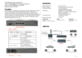
1.3 PRODUCT FEATURES ................................................................................................................................................................................................................................................................... 7
1.4 SPECIFICATIONS ......................................................................................................................................................................................................................................................................... 8
1.5 MANAGEMENT FEATURES ........................................................................................................................................................................................................................................................... 8
1.6 PANEL ..................................................................................................................................................................................................................................................................................... 9
1.6.1 Top & Front panel ......................................................................................................................................................................................................................................................... 9
1.6.2 Wall Mounting Holes & Inside the Media Converter .................................................................................................................................................................................................. 10
1.7 LED INDICATORS ..................................................................................................................................................................................................................................................................... 11
1.8 RESET TO DEFAULT BUTTON ...................................................................................................................................................................................................................................................... 12
CHAPTER 2 INSTALLATION ............................................................................................................................................................................................................................................ 13
2.1 CABLE TRAY MANAGEMENT ....................................................................................................................................................................................................................................................... 13
2.2 WALL MOUNTING .................................................................................................................................................................................................................................................................... 14
2.3 INSTALLATION OF SFP MODULES (FOR FTH4-1000MS ONLY) ........................................................................................................................................................................................................ 15
2.3.1 Inserting a Bale Clasp SFP Module into the Cage ........................................................................................................................................................................................................ 15
2.3.2 Removing a Bale Clasp SFP Module ............................................................................................................................................................................................................................ 15
CHAPTER 3 WEB BASED PROVISIONING ........................................................................................................................................................................................................................ 16
3.1 INTRODUCTION ........................................................................................................................................................................................................................................................................ 16
3.2 WEB LOGIN PAGE .................................................................................................................................................................................................................................................................... 16
3.3 WEB MAIN PAGE .................................................................................................................................................................................................................................................................... 17
3.4 SYSTEM INFORMATION ............................................................................................................................................................................................................................................................. 18
3.4.1 Network Information .................................................................................................................................................................................................................................................. 18
3.4.2 DD Information ........................................................................................................................................................................................................................................................... 19
3.5 LOCAL SETTINGS ...................................................................................................................................................................................................................................................................... 20
3.5.1 IP Configuration .......................................................................................................................................................................................................................................................... 21
3.5.2 Password Setting ........................................................................................................................................................................................................................................................ 22
3.5.3 Converter Configuration ............................................................................................................................................................................................................................................. 23
3.5.4 Port Configuration ...................................................................................................................................................................................................................................................... 26
3.5.5 MIB Counters .............................................................................................................................................................................................................................................................. 27
3.5.6 VLAN ........................................................................................................................................................................................................................................................................... 28
3.5.6.1 VLAN Group ....................................................................................................................................................................................................................................................................................... 28

5
3.5.6.2 VLAN Per Port Configuration .............................................................................................................................................................................................................................................................. 29
3.5.7 Management VLAN Setting ........................................................................................................................................................................................................................................ 30
3.6 REMOTE SETTINGS ................................................................................................................................................................................................................................................................... 31
3.7 802.3AH OAM FUNCTIONS ...................................................................................................................................................................................................................................................... 31
3.7.1 802.3ah Configuration ................................................................................................................................................................................................................................................ 32
3.7.2 Loop Back Test ............................................................................................................................................................................................................................................................ 34
3.7.3 802.3ah Status ............................................................................................................................................................................................................................................................ 35
3.8 TOOLS ................................................................................................................................................................................................................................................................................... 38
3.8.1 System Reboot ............................................................................................................................................................................................................................................................ 38
3.8.2 Save and Restore ......................................................................................................................................................................................................................................................... 39
3.8.3 Firmware Upgrade ...................................................................................................................................................................................................................................................... 40
3.9 LOGOUT ................................................................................................................................................................................................................................................................................. 41
3.10 TROUBLESHOOTING ................................................................................................................................................................................................................................................................ 42
3.10.1 Factory Default ......................................................................................................................................................................................................................................................... 42
3.10.2 Reset ......................................................................................................................................................................................................................................................................... 42
3.10.3 LED Observations ...................................................................................................................................................................................................................................................... 43
3.10.3.1 Power On ......................................................................................................................................................................................................................................................................................... 43
3.10.3.2 UTP Link Test .................................................................................................................................................................................................................................................................................... 43
3.10.3.3 Fiber Link Test .................................................................................................................................................................................................................................................................................. 43
3.10.4 Operation Checks ...................................................................................................................................................................................................................................................... 44
3.10.4.1 Converter Check ............................................................................................................................................................................................................................................................................... 44
3.10.4.2 Ping Test ........................................................................................................................................................................................................................................................................................... 44
3.10.4.3 Web Access Test .............................................................................................................................................................................................................................................................................. 45

6
Chapter 1 Introduction
1.1 Welcome
Thank you for choosing FTH4-1000MS & FTH4-100M Managed Gigabit & Fast Ethernet OAM/IP Media Converter with cable tray.
Throughout this document, the two different models of this family will be referred to as FTH4-1000M & FTH4-100M (FTH4-1000MS will also be
stated when necessary). If you would like to skip right to the installation of the media converter, proceed to Chapter 2.
This manual is used to explain the hardware installation procedures and operation of FTH4-1000M & FTH4-100M, and present its
capabilities and specifications. This manual is divided into 3 chapters, the Introduction, Installation, and Provisioning Chapters.
Installers should carefully read the Chapters 1 & 2, Introduction and Installation. The divisions in that manual are intended for use by
personnel to answer questions in general areas. Planners and potential purchasers may read the Introduction to determine the suitability of the
product to its intended use; Operating Personnel would use the Web Based Management Chapters and Appendices to become familiar with
the settings. Network Administrators should read the chapters on Web Based Management and Trouble Shooting to become familiar with the
diagnostic capabilities, network settings and management strategies.
1.2 Product Description
FTH4-1000M & FTH4-100M are managed electrical to optical media converters with cable tray for Gigabit & Fast Ethernet. There are two
models for FTH4-1000MS series, one with fixed optical transceiver (FTH4-1000M) and one supporting pluggable SFP transceiver (FTH4-
1000MS). These converters support embedded stand-alone Web based management over IP networks as well as IEEE802.3ah OAM for
remote in-band management.
FTH4-1000M & FTH4-100M are IEEE802.3ah OAM compliant copper to fiber Gigabit & Fast Ethernet solution housed in wall mountable
enclosure. These converters have a built-in cable tray that allows users to enclose excessive fiber within the converter. When deployed as a
stand-alone solution, this media converter incorporates an easy to use Web user interface for operation, administration and maintenance of
both locally and remotely connected FTH4-1000M & FTH4-100M converters. By offering 802.3ah OAM compliance, this converter can be
linked to any 802.3ah compliant fiber switch and support loop back and dying gasp functions.

7
1.3 Product Features
Auto-Cross over for MDI/MDIX at UTP port
Auto-Negotiation or Forced Manual mode for UTP port
Supports SFP for selectable Fast or Gigabit speed on fiber (for FTH4-1000MS only)
Supports 802.3X flow control Enable or Disable
Supports Jumbo Frames up to 9600 bytes
Supports 16 Tag VLAN Groups
Supports 802.1Q tagging
Ingress/Egress Bandwidth control with 64K granularity
Supports 802.3ah-OAM loop back and dying gasp (remote power failure detection)
Supports firmware upgrade via Web
Supports Digital Diagnostics (DOM) for supported SFP
Includes RMON counters
Supports password setting for authentication
Supports Link Fault Pass Through (LFP) Function
Supports Auto Laser Shutdown (ALS) Function
With built-in fiber cable tray
FTH4-1000MS SFP socket supports a wide range of standard SFP modules to address any network situation.
WARNING: Fiber optic equipment may emit laser or infrared light that can injure your eyes. Never look into an optical fiber or connector port.
Always assume that fiber optic cables are connected to an active laser light source.

8
1.4 Specifications
Model
Item
FTH4-1000M(S)
FTH4-100M
Optical Interface
Connector
Duplex SC, ST, FC (FTH4-1000M) or SFP cage
(FTH4-1000MS)
Duplex SC, ST, FC
Data rate
100/1000Base-X
100Base-FX
Duplex mode
Full duplex on fiber
Full duplex on fiber
Electrical Interface
Connector
RJ-45, shielded
RJ-45, shielded
Data rate
auto, 10Mbps (10Base), 100Mbps (100Base), or
1000Mbps (1000Base)
auto, 10Mbps (10Base) or 100Mbps (100Base)
Duplex mode
Full or Half (Auto)
Full or Half (Auto)
Cable
Cat 5e or better
Cat 5e or better
Indications
Power, Fiber Link, Fiber Speed, LAN Link, LAN Speed
Power, Fiber Link, LAN Link, LAN Speed
Power
Output Voltage
12VDC
Consumption
< 4W
< 4W
Dimensions
220 x 140 x 27mm (D x W x H)
220 x 140 x 27mm (D x W x H)
Weight
720g
720g
Temperature
0°C~60°C (Operating), -10°C~70°C (Storage)
0°C~60°C (Operating), -10°C~70°C (Storage)
Humidity
10 ~ 90% non-condensing
10 ~ 90% non-condensing
Certifications
CE, FCC, RoHS Compliant
CE, FCC, RoHS Compliant
MTBF
65000 hrs
65000 hrs
1.5 Management Features
Once configured for TCP/IP access, these units support a Web Smart GUI for intuitive setting via point & click.

9
1.6 Panel
1.6.1 Top & Front panel
FTH4-1000M & FTH4-1000MS FTH4-100M
Figure 1. Top panel Figure 2. Front panel
LED indicators
RJ-45 port
Cable holder
Reset to default
button

10
1.6.2 Wall Mounting Holes & Inside the Media Converter
Figure 3. Wall mounting holes Figure 4. Inside the media converter
Wall mounting
holes
Cable tray
management
Power DC jack
Fiber optic port

11
1.7 LED Indicators
FTH4-1000M & FTH4-100M have LEDs on the front face that report the condition of power, Fiber link & Speed, LAN link & Speed.
FTH4-1000M LED Indicators FTH4-100M LED Indicators
LED
Color
Status
Definition
Power
Green
ON
Light if power is connected.
OFF
Power is not connected.
Fiber Link
(FTH4-100M)
Green
ON steadily
Light when the fiber port has an optical link but no link activity.
Flashing
Flash when there is data traffic.
OFF
There is no optical link.
Fiber Link
(FTH4-1000MS)
Green
ON steadily
Light when the fiber port has an optical link but no link activity.
Flashing
Flash when there is data traffic.
OFF
There is no optical link.
Fiber Speed
(FTH4-1000MS)
Green
ON
Light when the Fiber speed is 100M.
Amber
ON
Light when the Fiber speed is 1000M.
OFF
There is no optical link.
LAN LINK
Green
ON steadily
Light when the LAN port has a link but no link activity.
Flashing
Flash when there is Ethernet traffic.
OFF
There is no LAN port link.
LAN Speed
Green
ON
Light when the LAN speed is 100M.
Amber
ON
Light when the LAN speed is 1000M. (for FTH4-1000MS only)
OFF
If not lit, the LAN speed of 10M is indicated.

12
1.8 Reset to Default Button
The “Reset to Default” button is located next to RJ-45 UTP port. It is used to recover lost password or to return TCP/IP settings to factory
default values. Use a pencil or blue-point pen and then press the button for 6 seconds then release to reset the device to the factory default
settings. DO NOT POWER OFF. Allow the device to again fully reboot.
Default values:
Login Username: admin
Password: admin
IP: 10.1.1.1
Netmask: 255.255.255.0
Gateway: 0.0.0.0

13
Chapter 2 Installation
2.1 Cable Tray Management
FTH4-1000M & FTH4-100M have built-in cable tray that is used to organize excessive fiber in order. The installation of fiber cable in the cable
tray is simple and straightforward. The following pictures describe the fiber installation step by step.
Step 1. Use the screwdriver to remove Step 2. Remove the top panel. Step 3. Connect one end of the fiber connector to
screws fixed on the top panel. the fiber optic port and t hen organize
excessive fiber in the cable tray.

14
2.2 Wall mounting
FTH4-1000M & FTH4-100M can not only be placed on the flat desk but also be mounted on the wall. The media converter provides three wall
mounting holes at the bottom panel that allows users to hang it vertically or horizontally depending on the actual wall mounting needs. The wall
mounting installation methods are simple and straightforward. Follow the steps below to hang the media converter on the wall.
Firstly, fix two or three screws (screws are not provided) on the wall. The distance between screws varies depending on the vertical or
horizontal direction of the media converter. Once the screws are fixed on the wall, hang the media converter on those screws securely.
Figure 5. Wall mounting (vertical) Figure 6. Wall mounting (horizontal)

15
2.3 Installation of SFP Modules (for FTH4-1000MS only)
We supplied SFP modules are of the Bale Clasp type. The bale clasp pluggable module has a bale clasp that secures the module into the
SFP cage and has a handle to aid in removing the module.
Bale Clasp type SFP
2.3.1 Inserting a Bale Clasp SFP Module into the Cage
Step 1 Close the bale clasp upward before inserting the pluggable module.
Step 2 Line up the SFP module with the port, and slide it into the cage. Seat it. Attach fiber cable.
2.3.2 Removing a Bale Clasp SFP Module
Step 1 Remove fiber cable. Open the bale clasp on the SFP module. Press the clasp downward with your index finger.
Step 2 Grasp the SFP module between your thumb and index finger and carefully remove it from the SFP cage.
Follow all ESD precautions when handling SFP modules.

16
Chapter 3 Web Based Provisioning
3.1 Introduction
In an effort to make Networking devices easier to configure, many devices can now be configured via a Web Page, which should be
familiar to all Internet users.
The webpage is accessed by the Default IP Address of the device from a Web Browser such as Internet Explorer or Firefox in the following
way:
http://10.1.1.1/ (Assuming the device has Default IP Address of 10.1.1.1)
Before accessing this device by web browser, the IP address must be known or it must be reset or changed to be used on the desired
network. Please refer to Chapter 1, section 1.8 for the factory reset procedure. For initial configuration, you must set your PC to the default IP
subnet and access this device that way. Then you can change the IP address through the web interface.
3.2 Web Login Page
Access the device via a web browser.
Enter the username 'admin' and password 'admin'. Then, click "Login".

17
3.3 Web Main Page
When you successfully access the device, the first page you will see look like the one provided below. In this manual, we use Gigabit
media converter’s (FTH4-1000M) Web configuration page as example. If you use Fast Ethernet media converter, some pages may vary.

18
3.4 System Information
3.4.1 Network Information
The information displayed on this page gives specific device, network information, and port status for the local FTH4-1000MS and for any
remote that is accessible via IEEE802.3ah OAM in-band management.

19
3.4.2 DD Information
The DD or DDOM information is read from the MSA compliant SFP module and can be displayed via the web user interface.

20
3.5 Local Settings
The following is a listing of the local settings that can be performed via the web interface for the Gigabit & Fast Ethernet media converter.
We will go through the settings here, one by one, in detail.
/