Page is loading ...

USER MANUAL
FMUX-01A
Fiber Optical Multiplexer
Standalone / Rack Type
4, 8, 12 or 16 Channel Modular Design
G.703 E1, T1(DS1)
Datacom V.35, X.21, RS-530, RS-449, RS-232
Ethernet 10/100Base-TX Bridge
SNMP Manageable


The information contained in this document is subject to change without prior notice.
The information in this publication has been carefully checked and is believed to be entirely accurate at the time of
publication. CTC Union Technologies assumes no responsibility, however, for possible errors or omissions, or for any
consequences resulting from the use of the information contained herein. CTC Union Technologies reserves the right to
make changes in its products or product specifications with the intent to improve function or design at any time and
without notice and is not required to update this documentation to reflect such changes.
CTC Union Technologies makes no warranty, representation, or guarantee regarding the suitability of its products for
any particular purpose, nor does CTC Union assume any liability arising out of the application or use of any product
and specifically disclaims any and all liability, including without limitation any consequential or incidental damages.
CTC Union products are not designed, intended, or authorized for use in systems or applications intended to support or
sustain life, or for any other application in which the failure of the product could create a situation where personal injury
or death may occur. Should the Buyer purchase or use a CTC Union product for any such unintended or unauthorized
application, the Buyer shall indemnify and hold CTC Union Technologies and its officers, employees, subsidiaries,
affiliates, and distributors harmless against all claims, costs, damages, expenses, and reasonable attorney fees arising
out of, either directly or indirectly, any claim of personal injury or death that may be associated with such unintended or
unauthorized use, even if such claim alleges that CTC Union Technologies was negligent regarding the design or
manufacture of said product.
TRADEMARKS
Microsoft is a registered trademark of Microsoft Corp.
HyperTerminal™ is a registered trademark of Hilgraeve Inc.
WARNING:
This equipment has been tested and found to comply with the limits for a Class A digital device, pursuant to Part 15 of
the FCC Rules. These limits are designed to provide reasonable protection against harmful interference when the
equipment is operated in a commercial environment. This equipment generates, uses, and can radiate radio frequency
energy and if not installed and used in accordance with the instruction manual may cause harmful interference in which
case the user will be required to correct the interference at his own expense. NOTICE: (1) The changes or modifications
not expressively approved by the party responsible for compliance could void the user's authority to operate the
equipment. (2) Shielded interface cables and AC power cord, if any, must be used in order to comply with the emission
limits.
CISPR PUB.22 Class A COMPLIANCE:
This device complies with EMC directive of the European Community and meets or exceeds the following technical
standard. EN 55022 - Limits and Methods of Measurement of Radio Interference Characteristics of Information
Technology Equipment. This device complies with CISPR Class A.
WARNING:
This is a Class A product. In a domestic environment this product may cause radio interference in which case the user
may be required to take adequate measures.
CE NOTICE
Marking by the symbol CE indicates compliance of this equipment to the EMC directive of the European Community.
Such marking is indicative that this equipment meets or exceeds the following technical standards:
EN 55022:1994/A1:1995/A2:1997 Class A and EN61000-3-2:1995, EN61000-3-3:1995 and EN50082-1:1997

CTC Union Technologies Co., Ltd.
Far Eastern Vienna Technology Center (Neihu Technology Park)
8F, No. 60, Zhouzi St.
Neihu, Taipei, 114
Taiwan
Phone: +886-2-2659-1021
FAX: +886-2-2799-1355
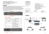
FMUX-01A
Platform fiber multiplexer with 4, 8, 12, 16 channels E1, T1, Data communication, or
10/100Base-TX Ethernet Bridge.
Installation and Operation Manual
Version 1.0 Mar 2004 Released for first printing
Version 1.1 July 2005 Added Datacom Loopback & Timing
Version 1.2 Apr 2006
This manual supports the following models:
FMUX-01A
This document is the third official release manual. Please check CTC Union's website for any
updated manual or contact us by E-mail at info@ctcu.com. Please address any comments for
improving this manual or to point out omissions or errors to [email protected]. Thank you.
The information and specifications in this document are subject to change without notice.

Table of Contents
i
Chapter 1. Introduction
1.1 General......................................................................................................................................1
1.2 Functional Description..............................................................................................................1
1.3 Technical Specifications ...........................................................................................................4
1.4 E1 Signal Structure....................................................................................................................8
1.5 T1(DS1) Signal Structure..........................................................................................................8
1.6 Applications / Capabilities........................................................................................................9
Chapter 2. Port Card Overview
2.1 Introduction.............................................................................................................................11
2.2 Port Card Overview.................................................................................................................11
2.3 4 x E1 I/F Module Overview...................................................................................................11
2.4 4 x T1 I/F Module Overview...................................................................................................11
2.5 External Clock Overview........................................................................................................11
2.6 4 x Data I/F Module Overview ...............................................................................................12
2.7 Ethernet Bridge Module Option..............................................................................................17
Chapter 3. Installation
3.1 General....................................................................................................................................19
3.2 Site Preparation.......................................................................................................................19
3.3 Mechanical Assembly.............................................................................................................19
3.4 Electrical Installation...............................................................................................................20
3.4.1 Power connection..............................................................................................................20
3.4.2 Rear and Front panel connectors.......................................................................................21
3.5 Removal/Replacement Procedures..........................................................................................22
3.5.1 Optical Module Removal / Replacement (Hot Swappable).............................................22
3.5.2 Channel Port I/F Module Removal / Replacement ...........................................................23
3.5.3 Top cover Removal / Replacement for internal access.....................................................24
3.5.4 External Clock Feature Removal / Replacement ..............................................................25
3.5.5 SNMP Feature Removal / Replacement............................................................................26
Chapter 4. Operation
4.1 Introduction.............................................................................................................................27
4.2 LCD Menu Operation..............................................................................................................27
4.2.1 Top Level Menus ..............................................................................................................28
4.2.2 Menu Table .......................................................................................................................30
4.3 Terminal Mode Operation.......................................................................................................31
4.4 Connecting to the Fiber Multiplexer.......................................................................................31
4.5 Configuring in Console Mode.................................................................................................32
4.5.1 Local or Remote Login .....................................................................................................33
4.5.2 Define System Parameters ................................................................................................33
4.5.3 System Configuration........................................................................................................34
4.5.4 System Reset.....................................................................................................................35
4.5.5 Optical Configuration........................................................................................................35
4.5.6 Port Option Configuration.................................................................................................35
4.5.7 Alarm Threshold Settings..................................................................................................39
4.5.8 Setting System Date and Time..........................................................................................40
4.5.9 Display System Status.......................................................................................................41
4.5.10 Alarm Buffer Display......................................................................................................41
4.5.11 Performance Display.......................................................................................................42
4.5.12 Alarm Cut Off .................................................................................................................42

Table of Contents
ii
Chapter 5. Loop Back Testing
5.1 General....................................................................................................................................43
5.2 Loop Back Modes...................................................................................................................43
5.2.1 Optical Loop Back............................................................................................................43
5.2.2 E1/T1/Datacom 4-Channel Port Card Loop Back............................................................44
5.2.3 Datacom (RS-530, V.35, X.21, RS-449, RS-232) 4-Channel Port Card Loop Back.......45
5.2.4 Datacom (RS-530, V.35, X.21, RS-449, RS-232) 4-Channel Port Card Timing.............46
Chapter 6. SNMP Operation
6.1 General....................................................................................................................................47
6.2 SNMP Operations....................................................................................................................47
6.3 The Management Information Base ........................................................................................48
6.4 MIB Structure..........................................................................................................................48
6.5 SNMP Communities................................................................................................................49
6.6 Configuring the SNMP Agent.................................................................................................49
6.7 Configure the SNMP Manager................................................................................................52
6.8 Save and Restart SNMP...........................................................................................................52
6.9 SNMP Upgrade via TFTP .......................................................................................................53
6.10 SNMP Object Details ...........................................................................................................53
6.11 SNMP Trap Messages ...........................................................................................................58

Chapter 1. Introduction
1 Version 1.2 Apr 2006
1.1 General
Thank you for choosing the Platform Fiber Multiplexer. If you would like to skip right to
the installation and configuration of the Multiplexer, proceed to Chapters 3 and 4.
The Fiber Multiplexer is a 1U (1.75") high standalone or 19/23" rack mountable
E1/T1/Data/LAN Bridge multiplexer over fiber link, built upon a highly flexible, modular design.
The Fiber Multiplexer provides an economic optical connection solution in high-density E1
and/or T1 installations such as between branch offices, where multiple high speed synchronous data
communications are required or to link a mix of platforms over a single fiber pair. By utilizing a
modular design, a large variety of configurations may be realized and the unit may be easily custom
tailored for each specific application when ordered. The 4-CHANNEL E1, T1, V.35 (X.21/RS-
530/RS-449) data, Ethernet Bridge Port cards and optical interface cards are all optional. The
standard unit is a chassis with local control and ordered with single or dual power. The appropriate
hot swappable optical interface cards may be selected to support multi-mode or single-mode fiber
cable operation, with a variety of transceiver power and connector options including ST™, SC, FC,
LC, or MT-RJ. WDM (Wave Division Multiplexing) optical interfaces are also available to provide
bi-directional transmission on a single fiber to reduce cost when using leased fiber links. The range
of transmission for optical connection is from 2Km (for multi-mode) up to 120Km (single mode).
External Clock Card (external or internal clock source) and SNMP Card (for local and remote
management purposes) may be optionally installed in the chassis.
1.2 Functional Description
The Fiber Multiplexer basic chassis is available in five power supply configurations.
Depending on the model, power may be derived from single AC 90~250VAC, single DC
+20~60VDC, dual AC 90~250VAC, dual DC +20~60VDC, or AC plus DC power sources. The
Fiber Multiplexer provides all Line Card connections on the rear panel. There are 4 slots
available for installation of 4-CHANNEL E1 or T1 Port Cards (ITU-T G.703 E1/T1), 4-
CHANNEL Data Port Cards (RS-530, X.21, RS-449, V.35, or RS-232), or Single-CHANNEL
Ethernet Bridge LAN Port Cards (10/100Base-TX) into the Fiber Multiplexer chassis. Each 4-
CHANNEL Port Card provides 4 individual channels of E1, T1, or Datacom per Port Card. The
Single-CHANNEL Ethernet Bridge LAN Port Card provides one 8.192Mb/s (4xE1 speed)
WAN link for 10/100Base Ethernet LAN bridging applications.
The 4-CHANNEL E1 Port Card has the option of using BNC (75 Ohm unbalanced) or RJ-
45 (120 Ohm balanced) connectors for E1 Line interface connections and supports four separate E1
channels at a transmission rate of 2.048Mb/s (transparent unframed E1) each.
The 4-CHANNEL T1 Port Card provides four RJ-45 (100 Ohm balanced) connectors for
T1(DS1) Line interface connections and supports four separate T1 (DS1) channels at a transmission
rate of 1.544Mb/s (transparent unframed T1) each.
The 4-CHANNEL Data Port Card provides four standard nx56/nx64Kb/s, up to 2.048Mb/s
for V.35 (or X.21, RS-530, RS-449, RS-232) DCE ports on MB34 (DB15, DB25, DB37, DB25)
female or male connectors (required adapter cables optional) for direct connection to terminal
equipment.
The Ethernet Bridge Port Card provides an RJ-45 connector for 10Base-T or 100Base-TX
Ethernet (auto negotiation) connections. The bridging function provides LAN to LAN segment
links which operate under the same network address space.
LEDs on the front panel will show both the channel statuses and any alarm indications for
installed port cards (except Ethernet card which display link status on the card itself).

Chapter 1. Introduction
2 Version 1.2 Apr 2006
The Fiber Multiplexer E1 and T1 Interface Cards fully meet all E1 and T1 specifications
including ITU-T G.703, G.704, G.732, G.733, G.823 and G.824. The Bridge Interface Card meets
all Ethernet specifications for IEEE802.3 and IEEE802.3u.
Each 4-CHANNEL Port Card features diagnostic capabilities for performing local loop
back or remote loop back (except for Ethernet Bridge card). The loop back function is controlled by
the front panel LCD menu, terminal mode (RS-232 console) or when the SNMP option board is
installed via Telnet or SNMP set commands.
Up to five clock source selections are provided. Without the external clock card option, the
unit operates from an internal free running oscillator. When the external clock card option is
installed, additional clock sources may be selected from the clock card's own internal oscillator or
from an external clock references for E1 PCM, E1 TTL, T1 PCM, or T1 TTL. All E1 and T1
equipment may connect to the Fiber Multiplexer without regard to master or slave timing. The
Fiber Multiplexer is completely transparent to clocking and data transmission. This makes
configuration of the MUX extremely easy.
The Fiber Multiplexer provides optical interfaces (1+1) that are completely redundant and hot
swappable. By utilizing a modular design, fiber type (single mode or multi mode), the optical power
margin requirement and connector type can be easily chosen at installation time. This provides an
extremely flexible main unit which is not tied to a fixed optical interface. When two optical
modules are installed, the secondary module is in "standby", in case of any failure in the primary
path. If the primary fiber path fails, the switchover time to the secondary fiber is less than 50
milliseconds (industry standard). The automatic fall over function of the fiber allows the fiber to
continue to run in the secondary fiber, even after primary fiber connection is restored. This will
avoid another 50 millisecond loss of transmission on all channels. The fiber path can also be forced
from primary to secondary or back through the LCD menu or terminal console.
When the Fiber Multiplexer is ordered with an optional SNMP Card, the card is installed
inside the chassis. Configuration is accomplished via local control on the asynchronous RS-232 port
with a standard VT-100 terminal, via Ethernet and Telnet, or via any standard SNMP network
management software over Ethernet. The Fiber Multiplexer also has a Windows™ based GUI
management program that communicates with the Fiber Multiplexer via SNMP protocol to
display all status in real time, configure the unit, provides performance monitoring, and display
alarm buffers and real time trap messages. If the SNMP Card option is not installed, local and
remote management is still possible via the unit's internal menu system accessible from the front
panel LCD and menu keys, or via the asynchronous RS-232 port with a standard VT-100 terminal.
The Fiber Multiplexer also includes the ability to do in-band remote configuration. Once
the fiber optic link has been established, the remote unit may be configured or status checked from
the local unit using any of the available management options.

Chapter 1. Introduction
3 Version 1.2 Apr 2006
P
P
P
W
W
W
R
R
R
-
-
-
2
2
2
D
D
D
C
C
C
P
P
P
W
W
W
R
R
R
-
-
-
1
1
1
A
A
A
C
C
C
P
P
P
o
o
o
r
r
r
t
t
t
1
1
1
C
C
C
a
a
a
r
r
r
d
d
d
P
P
P
o
o
o
r
r
r
t
t
t
2
2
2
C
C
C
a
a
a
r
r
r
d
d
d
P
P
P
o
o
o
r
r
r
t
t
t
3
3
3
C
C
C
a
a
a
r
r
r
d
d
d
P
P
P
o
o
o
r
r
r
t
t
t
4
4
4
C
C
C
a
a
a
r
r
r
d
d
d
M
M
M
a
a
a
i
i
i
n
n
n
B
B
B
o
o
o
a
a
a
r
r
r
d
d
d
A
A
A
s
s
s
s
s
s
y
y
y
S
S
S
N
N
N
M
M
M
P
P
P
C
C
C
a
a
a
r
r
r
d
d
d
E
E
E
x
x
x
t
t
t
e
e
e
r
r
r
n
n
n
a
a
a
l
l
l
C
C
C
l
l
l
o
o
o
c
c
c
k
k
k
O
O
O
p
p
p
t
t
t
i
i
i
.
.
.
2
2
2
O
O
O
p
p
p
t
t
t
i
i
i
.
.
.
1
1
1
F
F
F
/
/
/
W
W
W
The following photo, with graphics, shows the major components which make up the Fiber
Multiplexer (with the External Clock and SNMP options installed). This photo shows a unit with
E1-BNC card in port 1, X.21 data communications card in port 2, T1-RJ45 card in port 3, and
10/100Base Ethernet bridge in port 4.
Figure 1-1 : Fiber Multiplexer Major Components

Chapter 1. Introduction
4 Version 1.2 Apr 2006
1.3 Technical Specifications
E1 Link
Framing Unframed (transparent*)
Bit Rate 2.048 Mb/s
Line Code AMI
HDB3
Line Impedance Unbalanced 75 ohms (BNC)
Balanced 120 ohms (RJ-45)
Receiver sensitivity +3 to -12dB (short haul)
"Pulse" Amplitude Nominal 2.37V+/-10% for 75 ohms
Nominal 3.00V+/-10% for 120 ohms
"Zero" Amplitude +/-0.3V
Transmit Frequency Tracking
Internal Timing
(w/external clock card option)
+/-30 ppm
Jitter Performance According to ITU-T G.823
Performance monitoring According to ITU-T G.821
Complies With ITU-T G.703, G.704, G.706 and G.732
Interface Connectors RJ-45 (wire wrap connector also available)
BNC
Test Loops LLB (Local Loop Back)
NELB (Near End Loop Back)
RLB (Remote Loop Back)
RRLB (Request Remote Loop Back)
* Transparent to framing (ITU-T G.704); transparent to ISDN PRI (30B+1D) E1 transmissions
T1 Link
Framing Unframed (transparent)
Bit Rate 1.544 Mb/s
Line Code AMI
B8ZS
Line Impedance Balanced 100 ohms (RJ-45)
Receiver sensitivity +3 to -12dB (short haul)
"Pulse" Amplitude Nominal 3.00V+/-10% for 100 ohms
"Zero" Amplitude +/-0.3V
Transmit Frequency Tracking
Internal Timing
(w/external clock card option)
+/-30 ppm
Jitter Performance According to ITU-T G.824
Performance monitoring According to ITU-T G.821
Complies With ITU-T G.703, G.704, G.706 and G.733
Interface Connectors RJ-45 (wire wrap connector also available)
Test Loops LLB (Local Loop Back)
NELB (Near End Loop Back)
RLB (Remote Loop Back)
RRLB (Request Remote Loop Back)
Optical Interface
Bit Rate 51.84Mbps
Line code Scrambled NRZ
Protection 1+1 redundant, hot swappable modules
Switch over time <50ms

Chapter 1. Introduction
5 Version 1.2 Apr 2006
Data Port Channels
Interface Types V.35
X.21
RS-530/V.36
RS-449
RS-232
Interface Connectors
V.35 Interface
X.21 Interface
RS-530 Interface
RS-449 Interface
RS-232 Interface
(provided by 1 to 4 header adapter cables)
34 pin, Female or Male
15 pin, D-type Female or Male
25 pin, D-type Female or Male
37 pin, D-type Female or Male
25 pin, D-type Female or Male
Line Code NRZ
Data Rate (each channel) nx64Kb/s (64 ~ 2048Kb/s)
where n equal 1 to 32
RS-232 maximum is 128Kb/s
Clock Modes Transparent, recovery, External, or Internal
Control Signals CTS constantly ON or follows RTS
DSR constantly ON, except during test loops
DCD constantly ON, except during signal loss
Test Loops LLB (Local Loop Back)
RLB (Remote Loop Back)
V.54
Bridge Port Channels
Interface Type 10Base-T, 100Base-TX (auto-negotiation)
Interface Connector RJ-45
WAN Data Rate 8.192Mb/s
Complies with IEEE802.3 10Base-T
IEEE802.3u 100Base-TX
Configuration modes bridge/repeater, full/half, 10/100, auto
Test Loops NONE
Local Setup and Configuration
LCD 2 rows of 16 characters
Pushbutton Switches ESC
Left Arrow (-)
Right Arrow (+)
Enter
Alarm Output Relays
Alarm Output Four pairs of Normally Open contacts for Major
and Minor alarms, both audio and visual.
Contact ratings: 1A at 30 VDC resistive
or 0.5A at 125 VAC resistive
Pin Assignment (DB9F) 1 - 2 / Major (audio)
3 - 4 / Major (visual)
5 / frame ground
6 - 7 / Minor (audio)
8 - 9 / Minor (visual)

Chapter 1. Introduction
6 Version 1.2 Apr 2006
LED Indicators
Power 1
Green Power Module 1 active
Power 2 Green Power Module 2 active
Optical 1 Amber Off = off
On = working (ALS is off)
On = working & linked (ALS is set Auto)
Blinking = working & not linked
(If ALS is disabled, then the not linked condition will
not be indicated by a blinking LED)
Optical 2 Amber Off = disabled
On = standby (ALS is off)
On = standby & linked (ALS is set Auto)
Blinking = Standby & not linked
(If ALS is disabled, then the not linked condition will
not be indicated by a blinking LED)
Channels GREEN One LED for each channel (A-D) of each Port (1-4)
or a total of 16 LED.
On = In Service
Off = Out of Service
Blinking = Loss of Signal
Audible Alarm
Cutoff
Amber Audible Alarm has sounded, alarm cutoff switch has
been pushed
Minor Alarm Amber Indicates a minor alarm has occurred, includes E1 or
T1 BPV or fiber sync slip.
Major Alarm RED Indicates a major alarm has occurred, includes E1,
T1, and fiber signal loss.
Far End Error Amber Indicates a far end (remote) error has occurred
Near End Error RED Indicates a near end (local) error has occurred
System Failure RED Indicates a failure in the "system" such as fiber LOS
Optical (Dual) GREEN = optical link established
RED = optical link failure
E1 (Dual) GREEN = E1 active, no error
RED = E1 Signal Loss
Off = No E1
T1 (Dual) GREEN = T1 active, no errors
RED = T1 Signal Loss
Off = No T1
RS-232 Console Port
Port interface RS-232D asynchronous, DCE
Port connector RJ-45
Data rate (*default) 19200 bps
Data format -One start bit
-8 data bits
-No parity
-One stop bit
RJ-45 Pin Usage
RJ-45(DCE) DB9(DTE)
4 GND 5
5 TD 2
6 RD 3

Chapter 1. Introduction
7 Version 1.2 Apr 2006
Optical Specifications (secondary fiber need not be identical to primary)
Standard Types WDM Types*
Type M-M S-M S-M S-M S-M S-M S-M S-M S-M
Distance (Km) 2 15 30 50 120 20(A)* 20(B)* 40(A)* 40(B)*
Tx:1310 Tx:1550 Tx:1310 Tx:1550
Wavelength
(nm)
1310 1310 1310 1310 1550
Rx:1550 Rx:1310 Rx:1550 Rx:1310
BER** <10
-
11
<10
-
11
<10
-
11
<10
-
11
<10
-
11
<10
-
11
<10
-
11
<10
-
11
<10
-11
Sensitivity
-31dBm -32dBm -35dBm -36dBm -35dBm -32dBm -32dBm -32dBm -32dBm
Output Power
-20dBm -20dBm -15dBm -8dBm 0dBm -18dBm -15dBm -10dBm -7dBm
Power Margin
11dB 12dB 20dB 28dB 35dB 14dB 17dB 22dB 25dB
Return Loss
-12dBm -12dBm -12dBm -12dBm -12dBm -14dBm -14dBm -14dBm -14dBm
ST v v v v v
SC v v v v v v v v v
LC v v v v v
MT-RJ
v v v v v
Conn.
Types
FC v v v v v
M-M: multi-mode S-M: single-mode [All optical transceivers are rated Class A.]
* WDM types must match (A) with (B) in pairs
** Bit Error Rate
All fiber transceivers in the Multiplexer incorporate an automatic laser shutdown feature
(ALS) designed to protect personnel that may come into contact with a disconnected fiber
connection. This feature may also be disabled for testing purposes via the front panel LCD, console
terminal mode or SNMP (when SNMP option is installed). The fiber module ports may be
independently installed with any of the above fiber features and must only match the remote side's
module. Fiber modules are completely hot swappable and may be replaced in the field without
taking the unit out of service.
Physical
Height: 43 mm (1.75")
Width: 438 mm (17.25")
Depth: 251 mm (9.875")
Weight: 4.5 kg (10 lb.) Net
Power supply
Voltage (AC source) 90 ~ 250 VAC
Voltage (DC source) 20 ~ 60 VDC
Frequency 47 to 63 Hz for AC power
Power consumption 40 VA (~ 40 watts)
Environment
Temperature
0-50
o
C / 32-122
o
F
Humidity 0 to 90% non-condensing
Heat Dissipation <100 BTU/hr
Miscellaneous
MTBF 87,116 hours (+/- 5%)
Emission compliance meets FCC part 15 Sub B (class A)
EN55022:1994/A1:1995/A2:1997,
EN61000-3-2:1995, EN61000-3-3:1995,
and EN50082-1:1997

Chapter 1. Introduction
8 Version 1.2 Apr 2006
1.4 E1 Signal Structure
E1 link line rate
The E1 line operates at a nominal rate of 2.048Mb/s.
E1 link line coding
The basic E1 line signal is coded using either the Alternate Mark Inversion (AMI) or HDB3
rule.
In the AMI format, "ones" are alternately transmitted as positive and negative pulses, whereas
"zeros" are transmitted as a zero voltage level. AMI is not used in most 2.048Mb/s transmissions
because synchronization loss occurs during long strings of data zeros.
In the HDB3 format, a string of four consecutive zeros is replaced with a substitute string of
pulses containing an intentional bipolar violation. The HDB3 code substitutions provide high pulse
density so that the receiving equipment is able to maintain synchronization with the received signal.
The 4-CHANNEL E1 Port Card supports two E1 line codes:
AMI coding.
HDB3 coding.
The 4-CHANNEL E1 Port Card supports only transparent unframed format. ie. The E1 will
pass through with its original framing structure completely intact.
1.5 T1(DS1) Signal Structure
T1 link line rate
The T1 line operates at a nominal rate of 1.544Mb/s.
T1 link line coding
The basic T1 line signal is coded using either the Alternate Mark Inversion (AMI) or B8ZS
rule.
In the AMI format, "ones" are alternately transmitted as positive and negative pulses, whereas
"zeros" are transmitted as a zero voltage level. AMI is not used in most 1.544Mb/s transmissions
because synchronization loss occurs during long strings of data zeros.
In the B8ZS format, a string of eight consecutive zeros is replaced with a substitute string of
pulses containing an intentional bipolar violation. The B8ZS code substitutions provide high pulse
density so that the receiving equipment is able to maintain synchronization with the received signal.
The 4-CHANNEL T1 Port Card supports two T1 line codes:
AMI coding.
B8ZS coding.
The 4-CHANNEL T1 Port Card supports only transparent unframed format. ie. The T1 will
pass through with its original framing structure completely intact.

Chapter 1. Introduction
9 Version 1.2 Apr 2006
1.6 Applications / Capabilities
In the following example, the Fiber Multiplexer utilizes an optical fiber connection between
a pair of units to provide 4, 8, 12 or 16 channels of E1, T1, Datacom, or 1 to 4 channels of Ethernet
Bridge between the units.
The timing scheme for typical E1 or T1 equipment is to transparently pass timing from a
timing source unit on one side, to a timing slaved unit on the other. Each of the up to 16 available
channels of the Fiber Multiplexer is independent of any other channel for framing or timing. For
datacom channels (V.35, X.21, etc.) full timing configuration is possible to either provide clock,
receive clock or to transparently pass clock from one device to the other.
Figure 1-2 : Typical Point-to-Point Application of Fiber Multiplexer

Chapter 1. Introduction
10 Version 1.2 Apr 2006
This page left blank intentionally.

Chapter 2. Port Card Overview
11 Version 1.2 Apr 2006
2.1 Introduction
This chapter provides a more descriptive over-view of the available 4-Channel Port card
options. Detailed specifications are in Chapter 1, while removal and replacement procedures are
detailed in Chapter 3. Unit configuration is all covered in Chapter 4. The cards are NOT designed to
be "hot" swappable, therefore make sure the Fiber Multiplexer chassis is powered off before
replacing a card or pulling it from the chassis. Removal and installation of 4-Channel Port Cards
with the rack chassis under power is NOT RECOMMENDED and will definitely effect the
operation of the other 4-Channel Port Cards (insertion and removal cannot be recognized by the
Fiber Multiplexer ).
2.2 Port Card Overview
The 4-Channel Port Cards for the Fiber Multiplexer are modular PCAs which slide into
the Fiber Multiplexer chassis, and interface with the internal "main board". The main board
provides an interface connection to the 4-Channel Port Cards for power, data connection and
other logic (for local management terminal and optional SNMP).
2.3 4 x E1 I/F Module Overview
The 4 x E1 4-Channel Port Cards for the Fiber Multiplexer are modular PCAs which slide
into the Fiber Multiplexer chassis and provide four completely independent ITU-T G.703 E1
interfaces. The PCA module terminates with a DB25F connector that is designed to connect to a
physical adapter. The adapter is available in two options, one, with 4 pairs of BNC connectors for
75 Ohm unbalanced connections and the other with four RJ-45 jacks for 120 Ohm balanced
connections.
2.4 4 x T1 I/F Module Overview
The 4 x T1 4-Channel Port Cards for the Fiber Multiplexer are modular PCAs which slide
into the Fiber Multiplexer chassis and provide four completely independent T1(DS1) interfaces.
The PCA module terminates with a DB25F connector that is designed to connect to a physical
adapter. The adapter is available with four RJ-45 jacks for 100 Ohm balanced connections.
2.5 External Clock Overview
The Fiber Multiplexer is available with an external clock option that allows the unit to be
synchronized with external clocks or equipment. The Fiber Multiplexer may receive an external
clock source from E1 PCM, E1 TTL, T1 PCM or T1 TTL signal sources. Additionally, the option
includes its own precision crystal based clock. The external clock is received via an RJ-45 jack
from the rear panel.
Ext Clk
1. Rx - (RRing)
2. Rx + (RTip)
Figure 2-1. External Clock Connector

Chapter 2. Port Card Overview
12 Version 1.2 Apr 2006
2.6 4 x Data I/F Module Overview
The 4 x Data 4-Channel Port Cards for the Fiber Multiplexer are modular PCAs which slide
into the Fiber Multiplexer chassis and provide four completely independent Data (V.35, X.21,
RS-530, RS-449, or RS-232) interfaces. The PCA module terminates with a HD62F connector that
is designed to connect to a physical adapter. The Data module is available in one of ten interface
and cable options.
1. 4 x V.35 with 4 MB34 Female connectors
2. 4 x V.35 with 4 MB34 Male connectors
3. 4 x X.21 with 4 DB15 Female connectors
4. 4 x X.21 with 4 DB15 Male connectors
5. 4 x RS-530 with 4 DB25 Female connectors
6. 4 x RS-530 with 4 DB25 Male connectors
7. 4 x RS-449 with 4 DB37 Female connectors
8. 4 x RS-449 with 4 DB37 Male connectors
9. 4 x RS-232 with 4 DB25 Female connectors
10. 4 x RS-232 with 4 DB25 Male connectors
When the Fiber Multiplexer is ordered with an X21 Port Card option, a 4-CHANNEL
X.21 Card and adapter cable are supplied with each DB15 wired according to the following table.
Signal
Function
DB15
PIN#
Abbreviation Direction Description
Shield 1 FG <->
Chassis ground.
May be isolated from signal ground.
Ground 8 SG <-> Common signal ground.
Transmit(A)
Transmit(B)
2
9
TD(A)
TD(B)
To MUX
UNIT
Serial digital data from DTE.
Receive(A)
Receive(B)
4
11
RD(A)
RD(B)
Fm. MUX
UNIT
Serial digital data at the output of the Fiber
Multiplexer receiver.
Control(A)
Control(B)
3
10
RTS(A)
RTS(B)
To MUX
UNIT
A ON signal to the Fiber Multiplexer when data
transmission is desired.
Indication(A)
Indication(B)
5
12
DCD(A)
DCD(B)
Fm. MUX
UNIT
Constantly ON, except when a loss of the
received carrier signal is detected.
Ext. Timing(A)
Ext. Timing(B)
7
14
ETC(A)
ETC(B)
To MUX
UNIT
A transmitted data rate clock input from the data
source.
Signal Timing(A)
Signal Timing(B)
6
13
RC(A)
RC(B)
Fm. MUX
UNIT
A received data rate clock for use by an external
data source.
Table 2-1 : DB15 adapter cable pin out for X.21

Chapter 2. Port Card Overview
13 Version 1.2 Apr 2006
When the Fiber Multiplexer is ordered with an V35 Port Card option, a 4-CHANNEL
V.35 Card and adapter cable are supplied with each MB34 wired according to the following table.
Signal
Function
MB34
PIN#
V.35
Circuit
Direction Description
Frame
Ground
A Frame <->
Chassis ground.
May be isolated from signal ground.
Signal
Ground
B Signal Ground <-> Common signal ground.
Transmit
Data
P
S
TD(A)
TD(B)
To MUX UNIT
Serial digital data from DTE.
Receive
Data
R
T
RD(A)
RD(B)
Fm. MUX
UNIT
Serial digital data at the output of the Fiber
Multiplexer receiver.
Request
To Send
C RTS To MUX UNIT
A ON signal to the Fiber Multiplexer when
data transmission is desired.
Clear
To Send
D CTS
Fm. MUX
UNIT
Constantly ON.
Data Set
Ready
E DSR
Fm. MUX
UNIT
Constantly ON,
Except during test loops.
Data Terminal
Ready
H DTR To MUX UNIT
DTR not used, used for a received serial data
rate clock input from the DTE.
Data Carrier
Detect
F DCD
Fm. MUX
UNIT
Constantly ON, except when a loss of the
received carrier signal is detected.
External
Transmit Clock
U
W
ETC(A)
ETC(B)
To MUX UNIT
A transmitted data rate clock input from the
data source.
Transmit
Clock
Y
AA
TC(A)
TC(B)
Fm. MUX
UNIT
A transmitted data rate clock for use by an
external data source.
Receive
Clock
V
X
RC(A)
RC(B)
Fm. MUX
UNIT
A received data rate clock for use by an
external data source.
Remote
Loopback
HH RL To MUX UNIT
When on, commands Fiber Multiplexer into
remote loop back.
Local
Loopback
JJ LL To MUX UNIT
When on, commands Fiber Multiplexer into
local loop back.
Test Indicator
KK TM
Fm. MUX
UNIT
ON during any test mode
Table 2-2 : MB34 cable pin out for V.35

Chapter 2. Port Card Overview
14 Version 1.2 Apr 2006
When the Fiber Multiplexer is ordered with an RS449 Port Card option, a 4-CHANNEL
RS-449 Card and adapter cable are supplied with each DB37 wired according to the following
table.
SIGNAL
FUNCTION
DB37
PIN
RS-449
CIRCUIT
Direction DESCRIPTION
Protective
Ground
1 Frame <->
Chassis ground.
May be isolated from signal ground.
Signal
Ground
19,20,
37
SG,RC,
SC
<-> Common signal ground.
Transmitted
Data
4
22
SD(A)
SD(B)
To MUX
UNIT
Serial digital data from DTE.
Received
Data
6
24
RD(A)
RD(B)
Fm. MUX
UNIT
Serial digital data at the output of the Fiber
Multiplexer receiver.
Request to
Sent
7
25
RS(A)
RS(B)
To MUX
UNIT
A ON signal to the Fiber Multiplexer when data
transmission is desired.
Clear to
Sent
9
27
CS(A)
CS(B)
Fm. MUX
UNIT
Constantly ON.
Data Set
Ready
11
29
DM(A)
DM(B)
Fm. MUX
UNIT
Constantly ON,
Except during test loops.
Data Terminal
Ready
12
30
TR(A)
TR(B)
To MUX
UNIT
DTR not used, used for a received serial data rate
clock input from the DTE.
Data Carrier
Detect
13
31
RR(A)
RR(B)
Fm. MUX
UNIT
Constantly ON, except when a loss of the received
carrier signal is detected.
External
Transmit clock
17
35
TT(A)
TT(B)
To MUX
UNIT
A transmitted data rate clock input from the data
source.
Transmit
Clock
5
23
ST(A)
ST(B)
Fm. MUX
UNIT
A transmitted data rate clock for use by an
external data source.
Receive
Clock
8
26
RT(A)
RT(B)
Fm. MUX
UNIT
A received data rate clock for use by an external
data source.
Remote
Loop back
14 RL
To MUX
UNIT
When on, commands Fiber Multiplexer into
remote loop back.
Local
Loop back
10 LL
To MUX
UNIT
When on, commands Fiber Multiplexer into local
loop back.
Test Indicator 18 TM
Fm. MUX
UNIT
ON during any test mode
Table 2-3 : DB37 adapter cable pin out for RS-449
/