Page is loading ...

USER MANUAL
FMUX04
Fiber Optical Multiplexer
Standalone / Rack Type
4 Channel Fixed Design
G.703 E1, T1(DS1)
SNMP Manageable (Optional)
FXS Order Wire (Optional)


The information contained in this document is subject to change without prior notice.
TRADEMARKS
Microsoft is a registered trademark of Microsoft Corp.
HyperTerminal™ is a registered trademark of Hilgraeve Inc.
WARNING:
This equipment has been tested and found to comply with the limits for a Class A digital
device, pursuant to Part 15 of the FCC Rules. These limits are designed to provide reasonable
protection against harmful interference when the equipment is operated in a commercial
environment. This equipment generates, uses, and can radiate radio frequency energy and if
not installed and used in accordance with the instruction manual may cause harmful
interference in which case the user will be required to correct the interference at his own
expense. NOTICE: (1) The changes or modifications not expressively approved by the party
responsible for compliance could void the user's authority to operate the equipment. (2)
Shielded interface cables and AC power cord, if any, must be used in order to comply with
the emission limits.
CISPR PUB.22 Class A COMPLIANCE:
This device complies with EMC directive of the European Community and meets or exceeds
the following technical standard. EN 55022 - Limits and Methods of Measurement of Radio
Interference Characteristics of Information Technology Equipment. This device complies
with CISPR Class A.
WARNING:
This is a Class A product. In a domestic environment this product may cause radio
interference in which case the user may be required to take adequate measures.
CE NOTICE
Marking by the symbol CE indicates compliance of this equipment to the EMC directive of
the European Community. Such marking is indicative that this equipment meets or exceeds
the following technical standards:
EN 55022:1994/A1:1995/A2:1997 Class A and EN61000-3-2:1995, EN61000-3-3:1995 and
EN50082-1:1997

CTC Union Technologies Co., Ltd.
Far Eastern Vienna Technology Center (Neihu Technology Park)
8F, No. 60, Zhouzi St.
Neihu, Taipei, 114
Taiwan
Phone: +886-2-2659-1021
FAX: +886-2-2799-1355
FMUX04 User Manual
Fiber Multiplexer with 4 channels E1 or T1
Version 1.0 Mar 2006
This manual supports the following models:
FMUX04
This document is the first official release manual. Please check CTC Union's website for any
updated manual or contact us by E-mail at in[email protected]. Please address any comments for
improving this manual or to point out omissions or errors to [email protected]. Thank
you.
The information and specifications in this document are subject to change without notice.

Table of Contents
i
Chapter 1. Introduction............................................................................................................. 7
1.1 General Description....................................................................................................... 7
1.2 Functional and Feature Description............................................................................... 7
1.3 Features List.................................................................................................................. 9
1.4 Packing List................................................................................................................... 9
1.5 Technical Specifications.............................................................................................. 11
1.5.1 E1 Link.................................................................................................................. 11
1.5.2 T1 Link.................................................................................................................. 11
1.5.3 Local Setup and Configuration.............................................................................. 12
1.5.4 RS-232 Console Port ............................................................................................. 12
1.5.5 LED Indicators ...................................................................................................... 12
1.5.6 Optical Specifications............................................................................................ 13
1.5.7 Transceiver Options............................................................................................... 13
1.5.8 Physical ................................................................................................................. 13
1.5.9 Power supply......................................................................................................... 14
1.5.10 Environment........................................................................................................ 14
1.5.11 Miscellaneous...................................................................................................... 14
1.6 E1 Signal Structure...................................................................................................... 14
1.6.1 E1 link line rate ..................................................................................................... 14
1.6.2 E1 link line coding................................................................................................. 14
1.7 T1(DS1) Signal Structure............................................................................................ 15
1.7.1 T1 link line rate ..................................................................................................... 15
1.7.2 T1 link line coding................................................................................................. 15
1.8 Applications / Capabilities........................................................................................... 15
Chapter 2. Installation ............................................................................................................ 17
2.1 General........................................................................................................................ 17
2.2 Site Preparation ........................................................................................................... 17
2.3 Unpacking ................................................................................................................... 17
2.4 Mechanical Assembly .................................................................................................. 18
2.5 Electrical Installation.................................................................................................... 19
2.5.1 Power connection, AC........................................................................................... 19
2.5.2 Power connection, DC........................................................................................... 19
2.6 Rear Panel Connectors ................................................................................................. 20
2.7 Front Panel Switches, Connectors and Indicators......................................................... 20
2.8 Removal/Replacement Procedures............................................................................... 21
2.8.1 Order Wire Feature Module Removal / Replacement........................................... 21
2.8.2 SNMP Feature Removal / Replacement................................................................ 22
Chapter 3. Operation .............................................................................................................. 23
3.1 Introduction.................................................................................................................. 23
3.2 DIP Switch Setting Detail............................................................................................. 23
3.3 Terminal Mode Operation........................................................................................... 24
3.4 Connecting to the FMUX04 ........................................................................................ 24
3.5 Configuring in Console Mode..................................................................................... 25
3.5.0 Local or Remote Login.......................................................................................... 25
3.5.1 Display System Status ........................................................................................... 26

Table of Contents
ii
3.5.2 Define System Parameters .....................................................................................27
3.5.3 Display Alarm Record ...........................................................................................35
3.5.4 Device Information................................................................................................35
3.6 Remote Configuration...................................................................................................36
Chapter 4. SNMP....................................................................................................................37
4.1 General.........................................................................................................................37
4.2 SNMP Operations.........................................................................................................37
4.3 The Management Information Base..............................................................................37
4.4 MIB Structure ...............................................................................................................38
4.5 SNMP Communities.....................................................................................................38
4.6 Configuring the SNMP Agent.......................................................................................39
4.6.1 Configure the SNMP Agent...................................................................................40
4.6.2 Manager Configuration..........................................................................................40
4.6.3 TFTP Server Configuration....................................................................................41
4.6.4 Save Configuration and Reboot the SNMP............................................................42
4.6.5 TFTP and Upgrade Firmware ................................................................................42
4.7 MIB File........................................................................................................................45
4.8 Web Based Interface.....................................................................................................46
4.8.1 Security Login........................................................................................................46
4.8.2 Unit Select..............................................................................................................46
4.8.3 Display System Status............................................................................................47
4.8.4 Realtime Display....................................................................................................47
4.8.5 System Configuration ............................................................................................48
4.8.6 Optical Configuration ............................................................................................48
4.8.7 E1/T1 Configuration..............................................................................................49
4.8.8 Phone Configuration..............................................................................................49
4.8.9 Alarm Configuration..............................................................................................50
4.8.10 Date & Time ........................................................................................................50
4.8.11 SNMP Setup.........................................................................................................51
4.8.12 Display Alarm Status ...........................................................................................53
4.8.13 Display Information.............................................................................................54
4.9 Telnet Management ......................................................................................................54
Appendix A. Miscellaneous....................................................................................................56
A.1 Console port pin assignment........................................................................................56
A.2 Alarm Relay Connection Detail...................................................................................56
A.3 Console cable pin assignment CAB-DB9DB9F-232-3................................................57
A.4 Phone pin assignment...................................................................................................57
A.5 E1/T1 RJ-45 pin assignment........................................................................................57
A.6 SNMP RJ-45 pin assignment .......................................................................................58
A.7 SNMP Trap Messages and Alarms ..............................................................................58
A.8 SNMP Object Details...................................................................................................59

Chapter 1: Introduction
7
Chapter 1. Introduction
Thank you for choosing the FMUX04. If you would like to skip right to the installation and
configuration of the Multiplexer, proceed to Chapters 2 and 3.
This manual is used to explain the installation and operating procedures for the FMUX04, 4
Port Fiber Optical E1/T1 Multiplexer, and present its capabilities and specifications. This
manual is divided into 5 Chapters, the Introduction, Installation, Operation, Loop Back
Testing and SNMP chapters. The Appendix includes the pin assignments of special cables
and gives further information on options for placing the device in service.
The divisions of the manual are intended for use by personnel to answer questions in general
areas. Planners and potential purchasers may read the Introduction to determine the suitability
of the product to its intended use; Installers should read the Installation Chapter and the
Cabling Specification Appendix; Operating Personnel would use the Operations Chapter to
become familiar with the line cards and settings. Operating Personnel and Network
Administrators should read the chapters on loop back testing and on SNMP to become
familiar with the diagnostic capabilities, network settings and management strategies when
the optional SNMP card is installed.
1.1 General Description
The FMUX04 is a 1U (1.75") high standalone or half rack mountable E1/T1 multiplexer over
fiber link designed for cost effective applications. The FMUX04 provides an economic
optical connection solution in low-density E1 or T1 installations such as between remote
offices, where multiple high speed synchronous TDM (Time Division Multiplexing)
communications are required over a single fiber pair. By utilizing a fixed channel design, the
unit is extremely cost effective and provides quick return on investment.
1.2 Functional and Feature Description
The standard unit is a standalone chassis with local control (DIP switch settable or via
Console port) and ordered with either AC or DC power. The appropriate optical transceiver
may be selected when ordering to support multi-mode or single-mode fiber cable operation,
with a variety of power and connector options including ST™, SC, FC, or LC. WDM (Wave
Division Multiplexing) optical transceivers are also available to provide bi-directional
transmission on a single fiber to reduce cost when using leased fiber links. The range of
transmission for optical connection is from 2Km (for multi-mode) up to 120Km (single
mode).
SNMP (for local and remote management purposes) and FXS Order Wire are options that
may be factory ordered or may be ordered separately for later installation in the unit. The
FMUX04 is available in three power supply configurations. Depending on the model, power
may be derived from single AC 100~240VAC, single DC +18~36VDC, or single DC
+36~72VDC power source. The FMUX04 provides all interface connections on the rear
panel. There are 4 channel connections for ITU-T G.703 E1/T1 on 4 x RJ-45 (USOC RJ-48C)
or 8 x BNC connectors. Each Channel connector provides an individual channel of E1 or T1,
depending on the unit's configuration.

Chapter 1: Introduction
8
When configured for E1 operation, the 4 channels of the FMUX04 may use either BNC (75
Ohm unbalanced) or RJ-45 (120 Ohm balanced) connectors for E1 Line interface
connections. Each separate E1 channel supports a transmission rate of 2.048Mb/s (transparent
unframed E1) each.
When configured for T1 operation, the 4 channels of the FMUX04 will use four RJ-45 (100
Ohm balanced) connectors for T1(DS1) Line interface connections. Each separate T1 (DS1)
channel supports a transmission rate of 1.544Mb/s (transparent unframed T1) each.
Three state LEDs (red, green or off) on the front panel will show both the channel statuses
and any alarm indications for the channels as well as the link status of the fiber optic link.
The FMUX04 E1 and T1 Interfaces fully meet all E1 and T1 specifications including ITU-T
G.703, G.704, G.732, G.733, G.823 and G.824.
Each E1/T1-CHANNEL features diagnostic capabilities for performing local loop back,
remote loop back, or to request remote loop back. The loop back function is controlled by
front panel DIP switch setting, terminal mode (RS-232 console) or, when the SNMP option
board is installed, via Telnet or SNMP set commands.
The FMUX04 unit's optical transmission operates from an internal free running oscillator. All
E1 or T1 equipment may connect to the FMUX04 without regard to master or slave timing.
The FMUX04 is completely transparent to clocking and data transmission. This makes
configuration of the MUX extremely simple. However, the FMUX04 provides no system
clock or clock source for the E1 or T1 connection. Therefore, the connected device on one
side must provide the required E1 or T1 clock timing (either internal clock or recovery
timing).
When the FMUX04 is ordered with optional SNMP, an additional hardware card is installed
inside the unit. Configuration is accomplished via the asynchronous RS-232 port with a
standard VT-100 terminal, via Ethernet and Telnet, or via any standard SNMP network
management software over Ethernet. If the SNMP option is not installed, local management is
still possible via the unit's internal menu system accessible from the asynchronous RS-232
port with a standard VT-100 terminal. Very basic configuration may also be done via the
front panel DIP switches, in which case the console functions are disabled.
The FMUX04 also includes the ability to do in-band remote configuration. Once the fiber
optic link has been established, the remote unit may be configured or status checked from the
local unit using any of the available management options, including SNMP.
The FMUX04 has the ability to upgrade its hardware and operational code by using the
Xmodem protocol on the serial interface. Local upgrades are supported with this feature.
TFTP upgrading of local or remote is supported when an optional SNMP module is installed.

Chapter 1: Introduction
9
When the FMUX04 is ordered with optional Order Wire, a hardware card is installed inside
the unit. The front panel's RJ-11 jack provides a "hot line" between the two FMUX04 units in
the link. Standard telephones may be connected to the RJ-11 jacks and when a phone is taken
"off hook", the remote side will automatically ring. Once answered, both parties may talk
normally. Following the conversation, both parties will place the phones back "on hook" and
the system is again ready for any direct line calls.
Included within the FMUX04 system unit is integrated optical BERT (Bit Error Rate Tester).
This feature provides a built-in pattern generator and receiver. The BERT function is
designed to run "in-band" allowing BER Testing and data transmission to co-exist on the fiber
media. This allows the BERT function to be running constantly even while the unit is in
service, without effecting normal customer data transmissions. The status of the error rate on
the optical connection may then be monitored via LED indicators on the front panel of the
FMUX04.
1.3 Features List
• Simple DIP switch or serial console setting.
• AC or DC models
• Non-redundant fiber for multi-mode and single mode, 2 to 120KM.
• Transceiver options include ST™, SC, FC, or LC. WDM (Wave Division Multiplexing)
• RJ-45 and BNC connectors for E1 and T1 connection.
• ITU-T G.703, G.704, G.732, G.733, G.823 and G.824 compliant.
• Fully transparent framing and timing.
• In band remote configuration supported.
• Optical and Electrical loop backs.
• Local and remote upgrade supported.
• Full time integrated Optical BER tester constantly monitors optical transmission.
• Order Wire (FXS) option.
• SNMP option.
1.4 Packing List
Upon opening your package, please check and be sure it contains the following items:
1. FMUX04 unit, AC or DC depending on modem ordered.
2. DB9F to DB9M, 1 meter, serial cable for console configuration.
3. User's Guide (hard copy or CDROM)
4. CDROM with MIB file (if SNMP option installed)
5. Clover Leaf to local power connector AC cable.
If any of these items are missing, please contact your distributor.

Chapter 1: Introduction
The following photo (AC model), with graphics, shows the major components which make up
the FMUX04 (with the Order Wire and SNMP options installed).
E1 BNC Connectors
AC Power Switch
Switching Power (AC)
Console Port
and Alarm Relay
Contacts
Optical
Transceive
r
DIP Switches
Order Wire Module
SNMP Module
Mainboard
SNMP Ethernet jack
E1 RJ45 Connectors
LED Indicators
Order
Wire
(phone)
Figure 1-1 : FMUX04 Major Components
10

Chapter 1: Introduction
11
1.5 Technical Specifications
1.5.1 E1 Link
Ports 4 fixed ports
Framing Unframed (transparent)
Bit Rate 2.048 Mb/s +/-50ppm
Line Code AMI
HDB3
Line Impedance Unbalanced 75 ohms (BNC)
Balanced 120 ohms (RJ-45)
Receiver sensitivity -43dB (long haul)
"Pulse" Amplitude Nominal 2.37V+/-10% for 75 ohms
Nominal 3.00V+/-10% for 120 ohms
"Zero" Amplitude +/-0.1V
Transmit Frequency Tracking
Recovery Timing
+/-50 ppm
Jitter Performance According to ITU-T G.823
Complies With ITU-T G.703 and G.823
Interface Connectors RJ-45 120 ohm (USOC RJ-48C)
BNC 75 ohm
Test Loops LLB (Local Loop Back)
RLB (Remote Loop Back)
RRLB (Request Remote Loop Back)
1.5.2 T1 Link
Ports 4 fixed ports
Framing Unframed (transparent)
Bit Rate 1.544 Mb/s +/-50ppm
Line Code AMI
B8ZS
Line Impedance Balanced 100 ohms (RJ-45)
Receiver sensitivity -36dB (long haul)
"Pulse" Amplitude Nominal 3.00V+/-20% for 100 ohms
"Zero" Amplitude +/-0.15V
Transmit Frequency Tracking
Recovery Timing
+/-50 ppm
Jitter Performance According to ITU-T G.824
Complies With ITU-T G.703 and G.824
Interface Connectors RJ-45 100 ohm (USOC RJ-48C)
Test Loops LLB (Local Loop Back)
RLB (Remote Loop Back)
RRLB (Request Remote Loop Back)

Chapter 1: Introduction
12
1.5.3 Local Setup and Configuration
DIP Switches A switch -12 pole, B switch - 2 pole
Console Port local VT-100 terminal connection
1.5.4 RS-232 Console Port
Port interface V.24/RS-232 asynchronous, DCE
Port connector DB9F
Data rate (*default) 19200 bps
Data format -One start bit
-8 data bits
-No parity
-One stop bit
DB9F Pin Usage
Cable pin definition
DB9M(DCE) DB9F(DTE)
5 GND 5
2 TD 2
3 RD 3
Alarm Relay contact
Contact ratings: 1A at 30 VDC resistive
or 0.5A at 125 VAC resistive
Pin
6 common
4 NO (*)
9 NC
* closed on alarm or closed if power fails or power is off
1.5.5 LED Indicators
Power Green On = Power active, Config by DIP switch
Flash = Config by console or SNMP
E1/T1 Mode Stateful Green = E1 mode (75 ohm)
Green/Flash = E1 mode (120 ohm)
Off = T1 mode (100 ohm)
Red/flash = Error in termination setting
Remote Error Stateful Green = remote no error
Red = remote has errors
Off = unknown or no optical link
Optical BER
(Bit Error Rate)
Stateful Green = 0 error rate
Green/flash = 0 to 10
-6
error rate
Red/flash = 10
-6
to 10
-3
error rate
Red = more than 10
-3
error rate
(Optical) Link Stateful Green = Link Good
Red = Link failure
E1/T1 Channel (1~4) Stateful Green = In Service
Off = Out of Service
Red = Loss of Signal
Red/flash = loop back test active
Active (Phone) Stateful Off = On Hook
Green = Off Hook & Connected OK
Green/flash = call out or incoming call (ringing)
Red/flash = Off Hook & connect failed
Red = No Phone Option Installed
SNMP (rear panel) Green Active: ON = SNMP active (flash 1/sec)
Active: OFF = no SNMP option
Link: ON= LAN link OK; OFF = No Link

Chapter 1: Introduction
13
1.5.6 Optical Specifications
Connector Type ST, SC, FC, LC, MT-RJ or WDM-SC (single fiber)
Optical mode Multi-mode or Single-mode
Wavelength 1310nm or 1550nm
Power Margin 11dB(2k,M/M), 12dB~35dB(15~120KM,S/M)
Line coding Scrambled NRZ
Data rate 10.922 Mbps
Bit Error rate Less than 10
-11
Test Loops LLB (Local Loop Back)
RLB (Remote Loop Back)
RRLB (Request Remote Loop Back)
1.5.7 Transceiver Options
Standard Types WDM Types*
Type M/M S/M S/M S/M S/M S/M S/M S/M S/M
Distance (Km) 2 15 30 50 120 20(A)* 20(B)* 40(A)* 40(B)*
Tx:
1310
Tx:
1550
Tx:
1310
Tx:
1550
Wavelength
(nm)
1310 1310 1310 1310 1550
Rx:
1550
Rx:
1310
Rx:
1550
Rx:
1310
BER** <10
-11
<10
-11
<10
-11
<10
-11
<10
-11
<10
-11
<10
-11
<10
-11
<10
-11
Sensitivity -31dBm -32dBm -35dBm -36dBm -35dBm -32dBm -32dBm -32dBm -32dBm
Output Power -20dBm -20dBm -15dBm -8dBm 0dBm -18dBm -15dBm -10dBm -7dBm
Power Margin 11dB 12dB 20dB 28dB 35dB 14dB 17dB 22dB 25dB
Return Loss -12dBm -12dBm -12dBm -12dBm -12dBm -14dBm -14dBm -14dBm -14dBm
ST
v v v v v
SC
v v v v v v v v v
LC
v v v v v
MT
RJ
v v v v v
Connector
Types
FC
v v v v v
M/M: multi-mode S/M: single-mode [All optical transceivers are rated Class A.]
* WDM types must match (A) with (B) in pairs
** Bit Error Rate
It is highly recommended that the fiber transceiver installed at the factory match the remote
side's fiber transceiver.
1.5.8 Physical
Height: 43 mm (1.75")
Width: 195 mm (7.75")
Depth: 248 mm (9.75")
Weight: 850 g (1 lb. 14 oz.) Net
930 g including Order Wire & SNMP

Chapter 1: Introduction
14
1.5.9 Power supply
Voltage (AC source) 100 ~ 240 VAC
Voltage (DC range 1) 18 ~ 36 VDC
Voltage (DC range 2) 36 ~ 72 VDC
Frequency 47 to 63 Hz for AC power
Power consumption 15 VA maximum
1.5.10 Environment
Temperature 0-50
o
C / 32-122
o
F
Humidity 0 to 90% non-condensing
1.5.11 Miscellaneous
MTBF 300,000 hours
Emission compliance meets FCC part 15 Sub B (class A)
EN55022:1994/A1:1995/A2:1997,
EN61000-3-2:1995, EN61000-3-3:1995,
and EN50082-1:1997
1.6 E1 Signal Structure
1.6.1 E1 link line rate
The E1 line operates at a nominal rate of 2.048Mb/s.
1.6.2 E1 link line coding
The basic E1 line signal is coded using either the Alternate Mark Inversion (AMI) or HDB3
rule. In the AMI format, "ones" are alternately transmitted as positive and negative pulses,
whereas "zeros" are transmitted as a zero voltage level. AMI is not used in most 2.048Mb/s
transmissions because synchronization loss occurs during long strings of data zeros.
In the HDB3 format, a string of four consecutive zeros is replaced with a substitute string of
pulses containing an intentional bipolar violation. The HDB3 code substitutions provide high
pulse density so that the receiving equipment is able to maintain synchronization with the
received signal.
When configured for E1, the 4-CHANNEL E1 Ports support one of two E1 line codes:
AMI coding.
HDB3 coding.
The 4-CHANNEL E1 Ports support only transparent unframed format. ie. The E1 will pass
through with its original framing structure completely intact.

Chapter 1: Introduction
1.7 T1(DS1) Signal Structure
1.7.1 T1 link line rate
The T1 line operates at a nominal rate of 1.544Mb/s.
1.7.2 T1 link line coding
The basic T1 line signal is coded using either the Alternate Mark Inversion (AMI) or B8ZS
rule. In the AMI format, "ones" are alternately transmitted as positive and negative pulses,
whereas "zeros" are transmitted as a zero voltage level. AMI is not used in most 1.544Mb/s
transmissions because synchronization loss occurs during long strings of data zeros.
In the B8ZS format, a string of eight consecutive zeros is replaced with a substitute string of
pulses containing an intentional bipolar violation. The B8ZS code substitutions provide high
pulse density so that the receiving equipment is able to maintain synchronization with the
received signal.
When configured for T1, the 4-CHANNEL T1 Ports support one of two T1 line codes:
AMI coding.
B8ZS coding.
The 4-CHANNEL T1 Ports support only transparent unframed format. ie. The T1 will pass
through with its original framing structure completely intact.
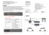
1.8 Applications / Capabilities
In the following example, the FMUX04 utilizes an optical fiber connection between a pair of
units to provide 4channels of E1 or T1 between the units. The timing scheme for typical E1 or
T1 equipment is to transparently pass timing from a timing source unit on one side, to a
timing slaved unit on the other. Each of the up to 4 available channels of the FMUX04 is
independent of any other channel for transparent framing or timing.
Figure 1-2 : Typical Point-to-Point Application of FMUX04
15

Chapter 1: Introduction
16
This page left blank intentionally.

Chapter 2. Installation
Chapter 2. Installation
2.1 General
The Installation chapter will cover the physical installation of the FMUX04, Standalone/Rack
Mount Fiber Optical Multiplexer, the electrical connections, interface connections and
cabling requirements. A brief overview of the functional components such as main unit, order
wire option and management options will also be outlined in this chapter.
Required Tools
You will need these tools to install the FMUX04:
Number 2 Phillips screwdriver for the 3mm and the 12-24 rack installation screws.
Wrist strap or other personal grounding device to prevent ESD occurrences.
Antistatic mat or antistatic foam to set the equipment on.
2.2 Site Preparation
Install the FMUX04 within reach of an easily accessible grounded AC outlet or site DC
power. The outlet should be capable of furnishing 100 to 240 VAC (18 to 36VDC or 36 to 72
VDC for DC supply). Allow at least 10cm (4 inch) clearance at the rear and front of the
FMUX04 for power lines and interface cables.
2.3 Unpacking
17
Inner cover
Transceiver
Cables
Outer cover
Figure 2-1. Unpacking the FMUX04.

Chapter 2. Installation
2.4 Mechanical Assembly
The FMUX04 is designed for standalone use, but it may be rack mounted as required with an
optional mounting kit. The rack installation only requires 1U space (1 3/4") in a standard EIA
19 inch rack. The FMUX04 is delivered completely assembled. No provision is made for
bolting the FMUX04 to a tabletop.
Figure 2-2. Single and tandem rack mounting of FMUX04.
18

Chapter 2. Installation
2.5 Electrical Installation
2.5.1 Power connection, AC
For a model with AC power supply, AC power (100~240VAC) is supplied to the FMUX04
through a becoming standard clover leaf 3-prong receptacle, located on the rear of the unit.
The FMUX04 should always be grounded through the protective earth lead of the power
cable in AC installations.
AC Input
2.5.2 Power connection, DC
For a model with DC power supply, DC -24V (18~36VDC) or DC -48V (36~72VDC) is
connected to the detachable terminal block. The DC power connector uses a 'Molex' type
connector with detachable terminal block. Please take extra caution to observe the proper
polarity of the DC when wiring the connector. The FMUX04 should always be grounded
through the protective earth lead via the frame ground connection for DC installations.
DC Input
18~36VDC 36~72VDC
Figure 2-3 : Supply connections, AC/DC models shown
19

Chapter 2. Installation
2.6 Rear Panel Connectors
The rear panel of the FMUX04 supports the E1 and T1 interface connection, the AC or DC
power connectors, the power switch and the Ethernet connector for connection to the LAN
network for SNMP control (when the SNMP option is installed). The FMUX04 routes the
signals from the 4 E1/T1 channels to the multiplexing circuitry and sends the multiplexed
signals to the Fiber Interface on the front panel.
Ethernet (SNMP)
Unbalanced E1
Balanced E1/T1
Figure 2-4 : Rear Panel Connections
2.7 Front Panel Switches, Connectors and Indicators
The front panel of the FMUX04, holds the optical interface, LED display, DIP switches and
RS-232 Console port/Alarm Relay connector. The optical interface is fixed at the factory per
order. The FMUX04 supports single mode or multimode transceiver with SC, ST, or FC
connector in powers that support 2, 15, 30, 50 or 120KM reach. The front panel also provides
the Order Wire phone jack that can directly connect to any standard telephone set.
DIP switches Optical Transceiver
Order wire phone
Terminal (NMS) and
Alarm Relay contacts
Tx Rx LED Display
Figure 2-5 : Front Panel Controls and Indicators
20
/