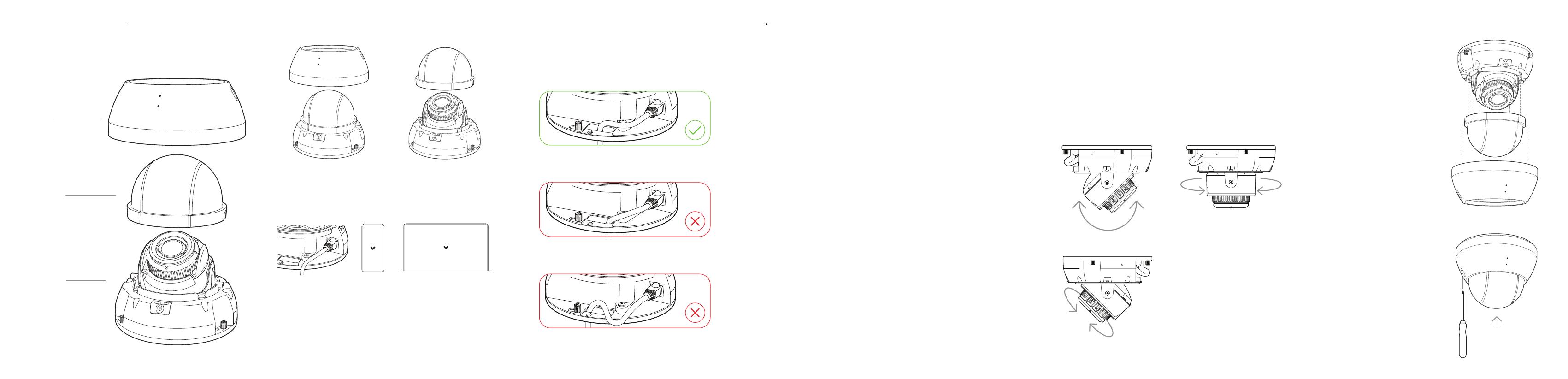
CD62 Assembly CD62 Mount
Please keep the protective lm adhered to the clear
bubble until completing the nal step of installation.
Top cover
Clear bubble
Camera base
Gently lift the clear bubble o
of the camera body. Due to the
magnetic attachment system,
there will be a small amount of
resistance.
Unscrew the 2 torx security
screws on the top cover. Remove
and set aside, while taking caution
not to scratch the clear bubble.
After positioning your camera
correctly, carefully place the
clear bubble back onto the
camera base. The 4 magnets
and 2 alignment features
on either side will guide the
bubble into position.
1. Mount the camera on a wall or ceiling. Try to keep the camera 8 to 10
feet above the ground.
2. For best night vision, avoid overhangs or obstructions. These may
reflect the camera’s IR illumination and reduce the image clarity in
night mode.
3. Use the provided T10 security torx security screwdriver to loosen
the screws and lift the cover. To remove the mount plate, loosen the
mount plate screws and twist the camera counter-clockwise. Lift the
camera vertically o the base plate and set aside.
4. Use the provided mounting template to mark wall mount holes. For
a junction box mount, use the mounting template to determine the
correct hole pattern.
5. For a solid material like wood or metal, drill ⁄ inch pilot holes. Drive
mounting screws directly into the pilot holes.
6. For drywall, drill ⁄ inch holes. Insert plastic anchors into holes and
drive mounting screws into anchors.
7. To secure the camera, place it over the mount plate screws and twist
counter-clockwise. Tighten the mount plate screws with a Phillips
screwdriver.
The status LED will turn orange to indicate the camera has power. The
LED will turn blue to indicate the camera is active. See additional LED
states and denitions under LED Behavior.
Gently pull the cable through the through-hole so it
has some slack, but will not interfere with the top cover.
Pulling the Ethernet cable too tight will strain
the cable which may impact data performance.
Too much slack in the Ethernet cable may create
top cover installation issues.
CD62 Secure
To secure the top cover, align
it to the security holes on
the baseplate. Tighten the 2
Torx security screws using the
provided T10 Security Torx
screwdriver.
Remove plastic lm after top
cover is secured.
60˚ 350˚
CD62 Adjust
350˚
Adjust your camera to the desired viewing angle.
Use the online stream to conrm image orientation.
Image can be flipped 180˚ online in Command.
Default image orientation is indicated by markings on the
lens face. Video orientation is also adjustable from within
the Verkada application.
Connect the camera to an 802.3af/at Power over Ethernet port on
your network.
Scan QR code on camera base
For easy registration and setup, scan the QR-code on the product.
If you prefer to manually register your product, please proceed to:
verkada.com/start.
1.0

