

Document
Document Details
Verkada Inc. 405 E 4th Ave, San Mateo, CA 94401
All specifications are subject to change without notice
Copyright © Verkada Inc. All rights reserved.
V1.6 (20230711)
(V1.0 first published 20211208)
Firmware
Firmware version can be verified on
Verkada Command command.verkada.com.
Product Models
This install guide pertains to models CD32-HW,
CD42-HW, CD52-HW.
2

Introduction
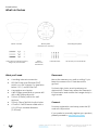
What’s in the box
What you’ll need
●A working Internet connection
●802.3af Power over Ethernet (PoE)
switch, or a PoE injector. For operation
below -20° C, use 802.3at PoE.
●A smartphone or laptop
●A #2 Phillips screwdriver or power drill
with a #2 Phillips driver bit
●1/4 inch (6.5mm) drill bit for wall
anchors
●1/8 inch (3mm) drill bit for pilot holes
●A Cat5 or Cat6 Ethernet cable with a
0.2-0.25 inch outside diameter
(5-6.5mm)
Verkada Inc. 405 E 4th Ave, San Mateo, CA 94401
All specifications are subject to change without notice
Copyright © Verkada Inc. All rights reserved.
Indoor Camera Mount plate
(Attached to camera)
Mounting template
3 M4 x 50mm machine screws,
wing nuts, and washers
4 Wall anchors T10 Security Torx screwdriver4 M4 x
25mm PH2
wall screws
Connect
For easy registration and setup, scan the QR
code on the product.
If you prefer to manually register your product,
please proceed to: verkada.com/start
3
Placement
Mount the camera on a wall or ceiling. Try to
keep the camera 8 to 10 feet above the
ground.
For best night vision, avoid overhangs or
obstructions. These may reflect the camera’s
IR illumination and reduce the image clarity in
night mode.

Introduction
Verkada Inc. 405 E 4th Ave, San Mateo, CA 94401
All specifications are subject to change without notice
Copyright © Verkada Inc. All rights reserved.
4
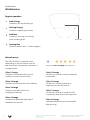
LED Behaviors
Regular operation
Solid Orange
Camera is on and booting up.
Flashing Orange
Camera is updating firmware.
Solid Blue
Camera is running, connected,
and recording data.
Flashing Blue
Generic network error. Contact support.
Network errors
1 Blue, 1 Orange
Camera is connected with PoE, but
unable to connect to the Switch.
1 Blue, 2 Orange
Camera has not received an IP address.
1 Blue, 3 Orange
Camera is not able reach the
configured Gateway.
1 Blue, 4 Orange
Camera has detected duplicate IP
addresses on the LAN.
The LED will flash in a specific order,
depending on the error state. You will
see 1 blue flash, followed by a number of
orange flashes.
Example of 1 Blue, 5 Orange flash sequence
1 Blue, 5 Orange
Camera is not able to resolve Verkada
hostnames.
1 Blue, 6 Orange
Camera is not able to receive a
response from the NTP Server.
1 Blue, 7 Orange
Camera is not able to certify the SSL
connection, likely due to SSL inspection.
1 Blue, 8 Orange
Verkada endpoints are not reachable
after boot up.
–
Status LED

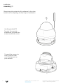
Installation
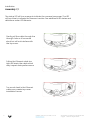
Assembly 1/2
Note
Please keep the protective film adhered to the clear
bubble until completing the final step of installation.
Use the provided T10
Security Torx security
screwdriver to loosen the
screws and lift the cover.
Verkada Inc. 405 E 4th Ave, San Mateo, CA 94401
All specifications are subject to change without notice
Copyright © Verkada Inc. All rights reserved.
Connect the camera to
an 802.3af/at Power
over Ethernet port on
your network.
5

Installation
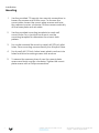
Assembly 2/2
Note
The status LED will turn orange to indicate the camera has power. The LED
will turn blue to indicate the camera is active. See additional LED states and
definitions under LED Behavior.
Verkada Inc. 405 E 4th Ave, San Mateo, CA 94401
All specifications are subject to change without notice
Copyright © Verkada Inc. All rights reserved.
Gently pull the cable through the
through-hole so it has some
slack, but will not interfere with
the top cover.
Pulling the Ethernet cable too
tight will strain the cable which
may impact data performance.
Too much slack in the Ethernet
cable may create top cover
installation issues.
6

Installation
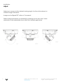
Mounting
Note
Verkada Inc. 405 E 4th Ave, San Mateo, CA 94401
All specifications are subject to change without notice
Copyright © Verkada Inc. All rights reserved.
1. Use the provided T10 security torx security screwdriver to
loosen the screws and lift the cover. To remove the
mount plate, loosen the mount plate screws and twist
the camera counter-clockwise. Lift the camera vertically
off the base plate and set aside.
2. Use the provided mounting template to mark wall
mount holes. For a junction box mount, use the
mounting template to determine the correct hole
pattern.
3. For a solid material like wood or metal, drill 1/8 inch pilot
holes. Drive mounting screws directly into the pilot holes.
4. For drywall, drill 1/4 inch holes. Insert plastic anchors into
holes and drive mounting screws into anchors.
5. To secure the camera, place it over the mount plate
screws and twist counter-clockwise. Tighten the mount
plate screws with a Phillips screwdriver.
7

Installation
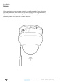
Adjust
Note
Adjust your camera to the desired viewing angle. Use the online stream to
confirm image orientation.
Image can be flipped 180˚ online in Command.
Default image orientation is indicated by markings on the lens face. Video
orientation is also adjustable from within the Verkada application.
Verkada Inc. 405 E 4th Ave, San Mateo, CA 94401
All specifications are subject to change without notice
Copyright © Verkada Inc. All rights reserved.
8

Installation
Secure
Note
After positioning your camera correctly, align the top shell security holes
with the baseplate and place the top shell back into its original position.
Tighten the security screws using the provided T10 security torx screwdriver.
Remove plastic film after top cover is secured.
Verkada Inc. 405 E 4th Ave, San Mateo, CA 94401
All specifications are subject to change without notice
Copyright © Verkada Inc. All rights reserved.
9

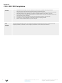
Appendix
CD32 CD42 CD52 Compliance
Caution 1. Maintenance and repair work must always be carried out by qualified technical personnel.
Disconnect power from the unit when performing a maintenance task.
2. Wiring methods used for the connection of the equipment to earth shall be in accordance with the
National Electrical Code, ANSI/NFPA 70, and the Canadian Electrical Code, Part 1, CSA C22.1.
3. The product must be installed and protected in a location that is not easily accessible and is away
from impacts or heavy vibration.
4. The device is only to be connected to PoE networks without routing to outside plants.
5. If powered by a power adapter, the adapter should be properly grounded.
6. Please contact certified dealers for power adapters.
PoE
Adapter
To reduce potential safety issues, only use the PoE adapter provided with the product, a replacement PoE
adapter provided by Verkada, or a PoE adapter purchased as an accessory from Verkada.
Verkada Inc. 405 E 4th Ave, San Mateo, CA 94401
All specifications are subject to change without notice
Copyright © Verkada Inc. All rights reserved.
10

Appendix
Support
Verkada Inc. 405 E 4th Ave, San Mateo, CA 94401
All specifications are subject to change without notice
Copyright © Verkada Inc. All rights reserved.
11
Thank you for purchasing this Verkada product. If for any
reason you're experiencing issues or need assistance, please
contact our 24/7 Technical Support Team immediately.
Sincerely,
The Verkada Team
verkada.com/support
-
 1
1
-
 2
2
-
 3
3
-
 4
4
-
 5
5
-
 6
6
-
 7
7
-
 8
8
-
 9
9
-
 10
10
-
 11
11


Ask a question and I''ll find the answer in the document
Finding information in a document is now easier with AI
Related papers
-
Verkada CF81-E Installation guide
-
Verkada CD22 / CD32 / CD42 / CD52 Indoor Dome Installation guide
-
Verkada CM41 Installation guide
-
Verkada CH52-E Installation guide
-
-
-
-
-
Verkada TD52 Video Intercom Installation guide
-
Other documents
-
Verkeda SV11 User guide
-
Henny Penny BW-4 User manual
-
-
-
-
-
-
-
-