
SV11 Environmental Sensor

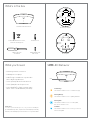
What’s in the box
SV11 Environmental Sensor
Mount plate
Mounting template
A
A,B
C,D,E
C,E
D
F
F
B
B
A,B
H
H
H
Level Line
Wall mount
4” Square junction box
European junction box
Single gang junction box
3.5” Round junction box
4” Round junction box
Pole mount straps
Verkada ACC-MNT-3 accessory
G
G
GG
4 wall anchors
T10 security Torx
screwdriver
4 M4 x 25mm PH2
wall screws
3 M4 x 50mm machine screws,
3 washers & 3 wing nuts
• A working internet connection
• A smartphone or laptop
• A #2 Phillips screwdriver or power drill
with a #2 Phillips driver bit
• ⁄ inch (6.5mm) drill bit for wall anchors
• ⁄ inch (3mm) drill bit for pilot holes
• A shielded Cat5 or Cat6 ethernet cable
with a .2-.25” outside diameter (5-6.5mm)
Please note:
To reduce potential safety issues, only use the PoE adapter
provided with the product, a replacement PoE adapter provided by
Verkada, or a PoE adapter purchased as an accessory from Verkada.
Solid Orange
This indicates that the sensor is on and booting up.
Flashing Blue
This indicates that the sensor is recording data,
but cannot reach the server.
Flashing Orange
This indicates that the sensor is updating rmware.
Solid Blue
This indicates that the sensor is running, connected,
and recording data.
LED
What you’ll need SV11 LED Behavior

Use the provided T10 security torx screwdriver to loosen the
screws and lift the cover.
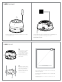
SV11 Connect
Insert the ethernet cable into the ethernet port. Scan the QR code
for easy sensor registration and setup, or proceed to:
www.verkada.com/start.
For best performance, mount the sensor on a ceiling, 8
ft above the ground.
Avoid windows, vents, and other sources of accelerated
air circulation.
The maximum detection range for air quality is 6 to 8 ft
from the sensor.
SV11 Mount
To remove the mount plate,
loosen the mount plate
screws and twist the sensor
housing counter-clockwise.
Lift the sensor housing
vertically o the base plate
and set aside.
Use the provided mounting
template to mark wall mount
holes. For a junction box
mount, use the mounting
template to determine the
correct hole pattern.
1
2
8’
6’ - 8’ max range
A
A,B
C,D,E
C,E
D
F
F
B
B
A,B
H
H
H
Level Line
Wall mount
4” Square junction box
European junction box
Single gang junction box
3.5” Round junction box
4” Round junction box
Pole mount straps
Verkada ACC-MNT-3 accessory
G
G
GG

1/8 inch
1/4 inch
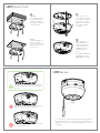
Plug in the sensor. The
status LED will turn
orange to indicate the
sensor has power. The
LED will turn blue to
indicate the sensor is
active.
See additional LED states
and denitions on the
SV11 LED behavior page.
To secure the sensor
housing, place it over the
mount plate screws and
twist counter-clockwise.
Tighten the mount plate
screws with a Phillips
screwdriver.
5
4
Drywall
For drywall, drill ⁄ inch
holes. Insert plastic
anchors into holes and
drive mounting screws
into anchors.
Solid Wall
For a solid material like
wood or metal, drill ⁄
inch pilot holes. Drive
mounting screws directly
into the pilot holes.
3
Gently pull the cable through the through-hole
so it has some slack, but will not interfere with the
top cover.
Pulling the ethernet cable too tight will strain the
cable which may impact data performance.
Too much slack in the ethernet cable may create
top cover installation issues.
To secure the sensor, align the top shell security holes with the
baseplate and place the top shell back into its original position.
Tighten the security screws using the provided T10 security torx
screwdriver.
SV11 Mount Cont.
SV11 Secure

Support
Thank you for purchasing a Verkada sensor.
If for any reason things don’t work right or you
need assistance, please contact us immediately.
Sincerely,
The Verkada Team
www.verkada.com/support
+1 (650) 514-2500
www.verkada.com/support
-
 1
1
-
 2
2
-
 3
3
-
 4
4
-
 5
5


Ask a question and I''ll find the answer in the document
Finding information in a document is now easier with AI
Other documents
-
Verkada D80 Installation guide
-
Verkada CD31 User guide
-
Verkada CD51 Installation guide
-
Verkada CD41 User guide
-
-
-
-
Verkada CF81-E Installation guide
-
-