Page is loading ...

VMAC – Vehicle Mounted Air Compressors
Toll Free: 1-888-241-2289
Fax: 1-250-740-3201
1
A700226 Retrofit Instructions
Intake Tube on Ford 6.7L VR150
Existing Kits
Instructions for VMAC Accessory A700226
V910010 Intake Tube Retrofit
V8 6.7L Diesel
Document: 1901035
Changes and Revisions
Version
Revision Details
Revised by /date
Checked by /date
Reviewed by /date
Implemented
A
Initial Release
MSP 8 Jan. 2016
DSB 13 Jan. 2016
CJH 13 Jan. 2016
13 Jan. 2016
The information in this manual is intended for certified VMAC installers
who have been trained in installation procedures and for people with
mechanical trade certification who have the tools and equipment to
properly and safely perform the installation. Do not attempt this
installation if you do not have the appropriate mechanical training,
knowledge and experience.
Follow all safety precautions for mechanical work. Any grinding,
bending or restructuring operations for correct fit in modified trucks must
follow standard shop practices.
Notice
Manuals are subject to change without notice.
Registered Trademarks
All trademarks mentioned in this manual are the property of their
respective owners. Their use by VMAC is for identification of the
manufacturers’ products only and does not imply any affiliation or
endorsement by said companies.
Loctite, Klean N’ Prime, 242 and PST are registered trademarks of
Henkel AG & Company KGaA.
Nylok is a registered trademark of Nylok Fastener Corporation.
Copyright 2016
All trademarks used in this manual are the property of the respective copyright
holder. The contents of this manual may not be reproduced in any form without the
express written permission of VMAC, 1333 Kipp Road, Nanaimo, BC V9X 1R3.
Printed in Canada

VMAC – Vehicle Mounted Air Compressors
Toll Free: 1-888-241-2289
Fax: 1-250-740-3201
2
General Information
Before You Start
Read this manual before attempting installation so that you can
familiarize yourself with the components and how they fit on the
vehicle. Identify variations for different engine models and different
situations that are listed in the manual. Open the package, unpack the
components and identify them.
Torque Specifications
All fasteners must be torqued to specifications. Use manufacturers
torque values for OEM fasteners. Apply Loctite 242® or equivalent
on all engine-mounted fasteners. Torque values are with Loctite
applied unless otherwise specified.
STANDARD GRADE 8 NATIONAL COARSE THREAD
Size
1/4
5/16
3/8
7/16
1/2
9/16
5/8
3/4
Foot-pounds
(ft-lb)
9
18
35
55
80
110
170
280
Newton meter
(N•m)
12
24
47
74
108
149
230
379
STANDARD GRADE 8 NATIONAL FINE THREAD
Size
3/8
7/16
1/2
5/8
3/4
Foot-pounds (ft-lb)
40
60
90
180
320
Newton meter (N•m)
54
81
122
244
434
METRIC CLASS 10.9
Size
M6
M8
M10
M12
M14
M16
Foot-pounds (ft-lb)
4.5
19
41
69
104
174
Newton meter (N•m)
6
25
55
93
141
236
Ordering Parts
To order parts, contact your VMAC dealer. Your dealer will ask for the
VMAC serial number, part number, description and quantity. To locate
your nearest dealer, call 1-800-738-8622 or online at
www.vmacair.com

VMAC – Vehicle Mounted Air Compressors
Toll Free: 1-888-241-2289
Fax: 1-250-740-3201
3
Important Safety Notice
The information contained in this manual is based on sound engineering
principles, research, extensive field experience and technical
information. Information is constantly changing with the addition of new
models, assemblies and service techniques. If a discrepancy is noted
in this manual, contact VMAC prior to initiating or proceeding with
service. Current information may clarify the issue. Any person with
knowledge of such discrepancies who performs service and repair
assumes all risks.
Only proven service procedures are recommended. Anyone who
departs from the specific instructions provided in this manual must first
assure that their safety and that of others is not being compromised and
that there will be no adverse effects on performance or the operational
safety of the equipment.
VMAC will not be held responsible for any liability, injuries, loss or
damage to individuals or to equipment as a result of the failure of any
person to properly adhere to the procedures set out in this manual or
standard safety practices. Safety should be your first consideration in
performing service operations. If you have any questions concerning
the procedures in this manual or require any more information on details
that are not included in this manual, please contact VMAC before
beginning repairs.
Safety Messages
This manual contains various warnings, cautions and notices that must
be observed to reduce the risk of personal injury during service or repair
and the possibility that improper service or repair may damage the
equipment or render it unsafe.
This symbol is used to call your attention to instructions
concerning your personal safety. Watch for this symbol; it
points out important safety precautions, it means, “Attention,
become alert! Your personal safety is involved”. Read the
message that follows and be alert to the possibility of
personal injury or death. Be alert; your safety is involved.
While it is impossible to warn about every conceivable
hazard, let good common sense be your guide.
This symbol is used to call your attention to instructions on a
specific procedure that if not followed may damage or
reduce the useful life of the compressor.
This symbol is used to call your attention to additional
instructions or special emphasis on a specific procedure.

VMAC – Vehicle Mounted Air Compressors
Toll Free: 1-888-241-2289
Fax: 1-250-740-3201
4
Preparing for Installation
Preparation for installation is very important. Missing a step or an item
can cause problems in the installation or damage to components.
Check off each item as it is completed so that you do not
miss any preparation steps.
□ Disconnect both batteries, (second one under driver’s door,
mounted to frame or other location), clean off any dirt, dust or
debris from air intake tube and air filter box areas.
□ Loosen hose clamps and remove both rubber elbows and intake
tube between air filter box lid and the rubber bellows leading to
the engine.
Figure 1.1 – Filter Box and Intake Tube
*Existing parts may differ slightly from that shown above.
Ensure no dirt or debris enters rubber bellows or air filter
box openings.

VMAC – Vehicle Mounted Air Compressors
Toll Free: 1-888-241-2289
Fax: 1-250-740-3201
5
Air Box Lid Removal
□ Disconnect MAF Sensor.
□ Remove Air Filter box lid, and filter element.
□ Remove the MAF sensor and the filter minder from the lid, and set
aside for re-use.
Lower Air Box Removal
□ Remove fastener at left front of air filter box where the 1/2"
compressor hose is held to the air filter box with a ‘p-clip’.
□ Remove nut, in bottom of air filter box and lift out filter box.
□ Remove rubber intake sleeve from front of air box. Keep the
sleeve, as it will be used with the modified air box. Do not reuse if
it has been modified. (Figure 1.2)
Rubber Sleeve
Figure 1.2 – Rubber Intake Sleeve
□ Remove foam piece from rear bottom of air box and save for
reuse later.
□ Remove fastener holding rear air filter box support bracket
(1200604) to inner fender and discard, if not previously removed.
Air Dam

VMAC – Vehicle Mounted Air Compressors
Toll Free: 1-888-241-2289
Fax: 1-250-740-3201
6
□ Remove OEM steel support bracket which had been locating the
air filter box, if not previously removed. (Figure 1.3)
Figure 1.3 – Air Filter Box Support Bracket
□ Remove OEM air dam. (Figure 1.4)
Figure 1.4 – OEM Air Dam
Remove OEM air duct
for modification
Air Dam

VMAC – Vehicle Mounted Air Compressors
Toll Free: 1-888-241-2289
Fax: 1-250-740-3201
7
Wiring Harness Protection and Routing
□ Locate the wiring harness guide. (Figure 1.5 / 1.6)
Figure 1.5 – Wiring Harness Guide
Figure 1.6 – Wiring Harness Guide Location
Plastic wiring harness guide
Second Threaded
OEM Hole
Forward Threaded
OEM Hole
OEM Air Duct to
be removed

VMAC – Vehicle Mounted Air Compressors
Toll Free: 1-888-241-2289
Fax: 1-250-740-3201
8
□ Unclip plastic wiring harness guide from sub frame by pressing on
clip and discard. (Figure 1.7)
Figure 1.7 – Wiring Harness Guide Clip
Remove wiring harness wrap so middle branch out of wiring can
be relocated towards the firewall. (Figure 1.8)
Figure 1.8 – Wiring Harness “Middle Branch”
Clip location on plastic guide
Wrap to be removed
Middle branch out of wiring

VMAC – Vehicle Mounted Air Compressors
Toll Free: 1-888-241-2289
Fax: 1-250-740-3201
9
□ Now that wiring harness wrap is removed take middle branch out
of wires and shift back along main wiring harness. (Figure 1.9)
Figure 1.9 – Relocate Middle Branch
□ Use electrical tape and wrap harness to secure middle branch out
of wires to main harness. (Figure 1.10)
Figure 1.10 – Tape Wrap
Middle branch out of wires
relocated back
Electrical tape wrap

VMAC – Vehicle Mounted Air Compressors
Toll Free: 1-888-241-2289
Fax: 1-250-740-3201
10
Glow Plug Module Bracket
□ Undo battery terminals on glow plug module bracket and remove
fuse block from bracket.
□ Remove fasteners holding glow plug module bracket to inner
fender, firewall and in wheel-well.
□ Undo fasteners holding the glow plug module on the bracket and
discard the glow plug bracket.
□ Attach the glow plug module to the new bracket using the supplied
fasteners.
Figure 1.11 – Glow Plug Module Bracket
□ Modify both OEM battery cable ends (positive and negative) by
removing the threaded stud from the battery cable ends and then
enlarging the stud holes to allow them to fit over each of the studs
on the glow plug module. The clamping portion of the battery
cable ends can also be cut off. (Figure 1.12)
Use caution when modifying the battery cable ends. Use
a vice or other means to hold and support the cable end
when drilling. A ‘step drill’ is recommended.
M8 Flat head Bolt (Supplied)
Positive Terminal Lock Nut
Negative Post
To Stud
on Firewall
Install Glow Plug Module
using M6 bolts (Supplied)

VMAC – Vehicle Mounted Air Compressors
Toll Free: 1-888-241-2289
Fax: 1-250-740-3201
11
Figure 1.12 – Modifying Battery Cables
□ If the battery cable clamping portions are not cut off it will look like
the image below. Be sure to wrap any exposed ‘positive’ clamp
with black electrical tape to prevent short circuiting. (Figure 1.13)
Figure 1.13 – Wrap Any Exposed “Positive” Clamp

VMAC – Vehicle Mounted Air Compressors
Toll Free: 1-888-241-2289
Fax: 1-250-740-3201
12
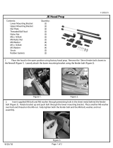
Updating the Hood Struts
□ Using a hammer, flatten the sheet metal, raised edge around the
lower hood strut area. (Figure 1.14)
Figure 1.14 – Preparing for UHMW Pad
□ Ensure there are no sharp edges remaining.
□ Remove countersunk fastener holding long leg of the glow plug
bracket to inner fender.
□ Align UHMW pad, supplied, with these two holes in inner fender
and the large portion of pad forward of holes. Reinstall glow plug
bracket flathead fastener. (Figure 1.15)
□ Install lower hood strut bracket with supplied fasteners. (Figure
1.15)
Flatten Sheet metal
edge

VMAC – Vehicle Mounted Air Compressors
Toll Free: 1-888-241-2289
Fax: 1-250-740-3201
13
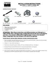
Figure 1.15 – Lower hood Strut and Glow Plug Module
□ Remove hood strut ball stud from passenger side of hood and
install into strut relocating bracket. Install relocating bracket with
supplied fasteners as shown. Note the 8mm hex nut may need to
be oriented to fit in the slot in hood. (Figure 1.16)
Figure 1.16 – Upper Hood Strut
□ Reinstall passenger side hood strut.
M8 x 16 Hex head Bolt
Lower Hood Strut
Relocating Bracket
M8 x 20 Flat head Bolt
UHMW Guard Pad
Glow Plug Module
OEM Hood
Strut Ball Stud
M8 Nut
Relocation Bracket
M8 x 18mm Bolts

VMAC – Vehicle Mounted Air Compressors
Toll Free: 1-888-241-2289
Fax: 1-250-740-3201
14
Complete Harness Routing
□ Use the 1.5” ID x 16.0” long protective wrap supplied and wrap
harness as shown. (Figure 1.17)
Figure 1.17 – Protective Wrap
□ Remove previously installed M6 screw and M6 nut from glow plug
module bracket and discard. Take loomed wire and route along
the top of main harness as shown. (Figure 1.18)
□ Use supplied 4.0” section of protective wrap and cover wiring
harness. (Figure 1.18)
□ Secure wiring harness to glow plug module using supplied M6 x
25mm screw, washer, P-Clip and M6 nut. (Figure 1.18)
Ensure protective wrap covers
harness fully down to bottom
section

VMAC – Vehicle Mounted Air Compressors
Toll Free: 1-888-241-2289
Fax: 1-250-740-3201
15
Figure 1.18 – Short Harness Wrap
□ Once installed bend P-clip down toward glow plug module to
provide clearance between P-clip and air box once installed.
(Figure 1.18 / 1.19)
Figure 1.19 – Harness Routing
□ Take washer fluid tube and loomed wire and route along the top of
the main wiring harness. Secure with supplied tie wraps.
(Figure 1.19)
Securing middle branch out of
wiring harness to bracket using
supplied P-clip, M6 bolt and nut
Route loomed wiring along top of
harness
Supplied 4.0” plastic wrap
covering wiring harness

VMAC – Vehicle Mounted Air Compressors
Toll Free: 1-888-241-2289
Fax: 1-250-740-3201
16
Figure 1.20 – Harness and Washer Fluid Tube Routing
□ Locate the sub frame nut insert which the front of the air box
mounts to, measure 6.0” down along sub frame and using 5.5mm,
or (13/64) drill until break through into hollow section. (Figure
1.21)
Figure 1.21 – Drill for P-Clip
□ Using supplied larger P-clip and secure wiring harness to sub
frame using self-tapping screw supplied. (Figure 1.22)
□ Once installed push down on P-clip toward fender liner to create
clearance for air box.
Tie wraps
Loomed wire, washer fluid
tube routed on top of main
harness
Sub frame nut insert
Drill here until break through
In to hollow section

VMAC – Vehicle Mounted Air Compressors
Toll Free: 1-888-241-2289
Fax: 1-250-740-3201
17
Figure 1.22 – Flatten P-Clip for Clearance
□ Install the supplied modified air dam.
□ Locate passenger side headlight wire and mass air flow sensor
wire and route overtop modified air dam once installed. (Figure
1.23)
Figure 1.23 – Wire Routing Around Modified Dam
□ After removing plastic wire guide, install plastic protective shell
over metallic heat tape on wiring harness routed alongside and
front of engine. Secure in place using tie wraps. (Figure 1.24)
Mass airflow connector wire
Head light wire
Note P-Clip is flattened
towards fender liner for
clearance

VMAC – Vehicle Mounted Air Compressors
Toll Free: 1-888-241-2289
Fax: 1-250-740-3201
18
Figure 1.24 – Anti-Abrasion Shell
Modify Inlet Valve Fittings
□ If the 3/16” push-to-connect fitting in the inlet valve is a straight
fitting, then remove the fitting and replace it with the supplied
3/16” 90 degree push-to-connect fitting. (Figure 1.25)
Figure 1.25 – Note Orientation of Fitting
This should be a 90 degree fitting
(Note orientation)
Protective shell
Metallic heat tape
Ensure his is a 90 degree fitting and Note orientation

VMAC – Vehicle Mounted Air Compressors
Toll Free: 1-888-241-2289
Fax: 1-250-740-3201
19
Intake Tube Brace
□ Remove OEM fastener holding ground-strap to firewall. (Figure
1.26)
Figure 1.26 – Intake Tube Brace and OEM Ground Wire
□ Use the OEM fastener to tap threads into the existing OEM hole
1-3/4” above the ground-strap hole. Remove OEM fastener and
retain. (6mm tap may also be used).
□ Install supplied brace and ground strap using OEM fastener into
lower hole and then the supplied fastener into the new threaded
hole above it. The brace should sit flush against the firewall with
the ground strap on top of the brace. Ensure the brace does not
make contact with the electrical connector on the firewall.
(Figure1.27)
Figure 1.27 – Intake Tube Brace and OEM Ground Wire
Tap hole using OEM Fastener
Remove OEM Fastener
from Ground Strap
OEM Ground Strap

VMAC – Vehicle Mounted Air Compressors
Toll Free: 1-888-241-2289
Fax: 1-250-740-3201
20
Inlet Brace Replacement
□ Remove the existing brace from the inlet and the front of the EGR
and discard fasteners.
□ Replace with the supplied thicker EGR brace. (Use supplied M6
bolts from Air End Fastener Pack, use Loctite© and torque to
specifications). (Figure 1.28)
Figure 1.28 – EGR Brace Bolt Locations
□ Replace inlet brace and install fasteners finger tight only. (Do not
use Loctite on these two (2) bolts). (Figure 1.29)
Figure 1.29 – Longest Bolts are used with Inlet Brace
Lower portion of inlet brace bolts here.
Lower Portion of Inlet Brace Bolts Here
/