Page is loading ...

FILTER MANUAL
RLP
Low Pressure
High Volume
312 SOUTH HWY. 73, PO BOX 398
FALLS CITY, NE 68355-0398
800-500-9777
®
Revision Date 04/23/2012

800-500-9777
Index
Introduction ...........................................................................................................................................i
Receiving Your Equipment............................................................................................................................... i
Safety Precautions .......................................................................................................................................... ii
Definitions ........................................................................................................................................... iii
The Filtration Process ......................................................................................................................... 1
High Temperature Precautions ....................................................................................................................... 1
Mechanical Operation .....................................................................................................................................1
Filter Media Properties........................................................................................................................ 3
Media Treatments ............................................................................................................................... 5
Installation ........................................................................................................................................... 6
Filter ................................................................................................................................................................ 6
Lubrication....................................................................................................................................................... 6
Bag and Cage Installation ............................................................................................................................... 6
Cartridge Filter Installation .............................................................................................................................. 7
RLP/MP Cage installation to “back” side of support channels.........................................................................8
Explosion vents ...............................................................................................................................................9
Operation .......................................................................................................................................... 11
Maintenance...................................................................................................................................... 12
Lubrication..................................................................................................................................................... 12
Cleaning and Repair ..................................................................................................................................... 12
Bags.............................................................................................................................................................. 12
Rotary Valve (Airlock) See airlock operation and maintenance manual. ....................................................... 12
Screw Conveyor............................................................................................................................................ 12
Speed Reducer (Arm Drive) .......................................................................................................................... 12
Magnehelic Gauge Operation ........................................................................................................... 13
Troubleshooting RLP Filters ............................................................................................................. 14
RLP Troubleshooting Worksheet .................................................................................................................. 15
Problem: High differential pressure across tubesheet................................................................................... 16
Problem: Low differential pressure across tubesheet.................................................................................... 17
Problem: Dust in exhaust air ......................................................................................................................... 17
Problem: Poor Bag Life .................................................................................................................................18
Problem: Hopper Plugging ............................................................................................................................ 18
Addendum: Cleaning Mechanism Assembly Dwg. 10532................................................................ 19
Addendum: Speed Reducer Manual (12 pages)
Addendum: Sprinkler Kit Layouts (12 pages)

FAX 402-245-5196 www.airlanco.com
i
800-500-9777
Introduction
RLP filters provide a mechanically simple, efficient, and economical means to separate particulate
from a gas stream. The absolute minimum of moving parts enhances the efficiency and durability of
the system. This manual will provide the information needed for an operator or maintenance
technician to understand the process of fabric filtration and the mechanical operation of your
AIRLANCO filter. Understanding these basic principles will assure that this filter will provide years
of dependable service with minimum maintenance.
Receiving Your Equipment
A visual inspection of your equipment should be performed before it is removed from the truck.
Dents, scratches, and other damage should be noted and photographed. The structural integrity of
the filter housing will be adversely affected by dents. AIRLANCO should be immediately notified of
any structural damage to your equipment. Packing lists should be checked thoroughly and
shortages should also be reported to AIRLANCO. It is the purchaser’s responsibility to file shortage
reports and damage claims with the carrier and the supplier. The carrier is responsible for any
damage to the equipment while it is in transit.
AIRLANCO, along with all of our employees, thanks you for selecting us to fulfill your needs
for environmental control equipment.

FAX 402-245-5196 www.airlanco.com
ii
800-500-9777
Safety Precautions
Warnings
Do not operate this equipment without guards, access doors, and covers secured.
Lock out power before servicing this equipment.
This equipment is automatically controlled and will start at any time without warning.
Do not enter clean air plenum while system fan is operating. Airflow can pull service door
closed causing severe injury or entrapment.
OSHA considers some filter housings a confined space. Follow procedures set forth by your
safety administrator.
FAILURE TO FOLLOW THESE INSTRUCTIONS MAY RESULT IN PERSONAL INJURY OR
PROPERTY DAMAGE!
READ AND UNDERSTAND SAFETY DECALS! (see below)

FAX 402-245-5196 www.airlanco.com
iii
800-500-9777
Definitions
ACR Air to Cloth Ratio. The velocity at which a gas moves through filter
media. Divide the gas volumetric flow rate (cfm) by the total area of
filtration media in (sq. ft.)
Agglomeration To gather into a mass.
Bag Filter element, sock. Usually supported by a wire cage.
Blinding Filter media becomes air impermeable due to moisture, temperature, or
other causes.
Cake Agglomeration of dust particles on the surface of a filter element.
Can Velocity Upward speed of air moving through a filter housing (fpm). Divide the
gas volumetric flow (cfm) by the cross sectional area of the baghouse
(sq. ft.)
Cartridge Filter Filter element consisting of a pleated filter media supported on a steel
or plastic skeletal frame.
CFM Cubic Feet per Minute –gas flow rate.
Clean Air Plenum Section of a baghouse directly above the tubesheet and filter bags or
cartridges.
Dew Point The temperature at which water vapor in a gas will condense into a
liquid state.
Filter Cake The accumulation of dust on a filter element before cleaning. This cake
assists in the filtration of dust.
Filter Element Refers to a filter bag or cartridge.
Header The pressurized pipe that contains the compressed air supply for
pulsing.
Inch of Water A unit of pressure equal to the pressure exerted by a column of water
one-inch in height at a standard temperature. 27.7 in. wg. = 1psi.
Interstitial Velocity The apparent velocity of a gas as it passes through the filter element
matrix. It is found by dividing the gas flow rate (cfm) by the cross
sectional area of the filter housing less the area occupied by the filter
elements.
Pressure Drop The resistance of flow of a fluid between two points.
Pulse Duration The length of time a cleaning pulse lasts.
Pulse Frequency The time between pulses in a baghouse cleaning system.
Pulse Jet Generic name given to all pulsing dust collectors.

FAX 402-245-5196 www.airlanco.com
iv
800-500-9777
Purge Pipe Pipe with holes in it that extends into a filter clean air
plenum and delivers cleaning air from the header to
the filter elements.
Re-entrainment The phenomenon whereby dust is collected from the air stream and
then is returned to the air stream. Occurs when dust is pulsed from a
filter element and then caught by an upward moving air stream.
Seeding The application of a relatively coarse, dry dust to a filter element before
start-up to provide an initial filter cake for immediate high efficiency and
to protect filter elements from blinding.
Tubesheet The steel plate from which the filter elements are suspended.
Separates the clean air and dirty sections of the baghouse.
Venturi Device used to increase the efficiency of a compressed air pulse.

FAX 402-245-5196 www.airlanco.com
1
800-500-9777
The Filtration Process
Filtration is a dry method of particulate collection in which an array of many individual targets is
assembled into a porous structure through which aerosol-laden gas is passed. In a filter, the
collection target is the filter media. Inertial, diffusional, electrostatic, and direct interception are the
primary forces that influence the collection of dry particulate on the filter media. As collection
proceeds, particles impinge upon previously collected particles and a deposit is built up which in
turn becomes the principal collection medium. This agglomeration of particles is referred to as a
“filter cake”. Filtration efficiency is not maximized until this filter cake has formed.
As the dust cake builds on the filter element surface it becomes increasingly difficult for the gas to
pass through the element. A differential pressure gauge mounted on the filter measures the force
required to move air through the filter media. Normal pressure drop for a filter will fall in the range
of 1 to 5 inches of water after the elements are broken in. The differential pressure reading will
increase as the elements get dirty. Eventually the dust cake must be removed from the filter
element surface or airflow will fall to unacceptable levels.
RLP filters are continuous self-cleaning units. A flow of low-pressure air from a centrifugal fan is
injected into each bag at periodic intervals. This air is distributed to each row of filter bags through
a rotating arm. Refer to cleaning mechanism drawing 10532 on page 19. The low-pressure
reverse flow of air from the fan gently cleans each bag. A percentage of the dust cake will fall away
from the bag into the filter hopper. It is normal for some of the dust to re-entrain onto the bag. The
rotating distribution arm turns at approximately 1 rpm. This slow speed virtually eliminates wear to
moving parts and seals. A ¾ HP gear motor drives the arm with a chain drive. The gear motor and
fan motor are explosion proof. The fan is a 3450 RPM direct drive fan requiring 460/230/60/3 AC.
Exact replacement parts can be obtained directly from AIRLANCO in Falls City, NE. (1-800-500-
9777).
High Temperature Precautions
Moisture is one of the most predominate causes for fabric filter failures. Care must be taken in
applications involving high humidity gas streams. Dryers and other combustion processes pose the
greatest danger for condensation in the filter. The filters and gas stream temperatures must be
maintained at 50oFabove the dew point of the gas stream. Excursions near or below the dew point
of the gas stream will result in condensation of the gas on the baghouse and filter media. This
moisture will change the desired dust cake into an undesirable mud cake, which is difficult to
remove, and may permanently damage the filter media. Corrosion is also intensified under these
conditions. Filters operating under high humidity conditions at any temperature should be protected
from gas condensation. This will require heating the filter to 50oF above the gas stream
temperature and insulation of the filter and ducting. Failure to take these precautions will result in
unsatisfactory performance of the equipment and possible catastrophic failure of the filter media.
Mechanical Operation
AIRLANCO RLP filters are available with either continuous or "on demand" cleaning controls.
Cleaning frequency can be controlled with a Dwyer Photohelic® pressure switch, which will
conserve energy, reduce bag wear, and lower emissions by maintaining a set pressure drop across
the filter bags. Filter bags are made from felted fibers and are supported on a rigid wire cage. The
composition of the fiber will vary depending on the dust and gas chemistry, temperature, and gas
stream humidity. Consult AIRLANCO Engineering (800-500-9777) for further information on the
characteristics and types of available filter media.
Bags are suspended in the filter from the tube sheet. The bag snaps into the tube sheet hole and is
self-supporting. A wire cage is then slipped into the bag and its top collar rests on top of the tube
sheet (refer to pg 6for illustration).

FAX 402-245-5196 www.airlanco.com
2
800-500-9777
Dust is collected on the surface of the filter bag and eventually forms a dust cake. When the
cleaning arm passes over a bag, low pressure air is injected into the filter bag opposite the normal
direction of the airflow through the bag. The bag will expand and the dust cake will break away.
This air will continue to pass through the bag in a reverse direction to further separate the dust cake
from it.
Separated dust falls into the hopper where it is removed through an airlock or other airtight device.
The airlock is placed at the discharge and allows the separated material to flow out while preventing
air from entering. Air leakage at the hopper’s discharge will cause re-entrainment of dust onto the
filter bags, which could contribute to high differential pressures.

FAX 402-245-5196 www.airlanco.com
3
800-500-9777
Filter Media Properties
Filter media is manufactured from various materials, which provide different beneficial
characteristics. Below is a Fabric Selection chart, which summarizes some of the properties of
common fabric materials.
MATERIAL
ACID
RESISTANCE
ALKALI
RESISTANCE
SOLVENT
RESISTANCE
STRENGTH &
ABRASION
FLAME
RESISTANCE
FILTRATION
PROPERTIES
RELATIVE
COST
OPERATING
TEMP °F
Polypropylene
E
E
E
E
P
G
1
180
Acrylic
G
F
G
G
P
G
2
260
Polyester
G
G
G
E
G
E
1
275
Ryton
E
E
E
G
E
V
6
375
Nomex
F
G
V
G
E
E
4
425
Teflon
E
E
E
G
E
F
8
450
Fiberglass
E
F
E
P
E
F
3
500
P-84
V
F
V
G
E
E
5
500
P= Poor, F= Fair, G= Good, V= Very good, E= Excellent
Polypropylene
This synthetic is available in both continuous filament and staple fiber form and is produced as
either a felt or woven material. Its major limitation is its low maximum continuous operating
temperature of 180°F (88°C). Oxidizing agents, copper, and related salts damage polypropylene.
Its primary benefit is that it is non-hygroscopic (does not chemically react with water). It exhibits
great resistance to static build-up and abrasion, and provides a slick surface for good dust cake
release during bag cleaning. Polypropylene is widely used in the food, detergent, chemical
processing, pharmaceutical, and tobacco industries.
Polyester
Today, polyesters are among the most widely used fabrics for general applications below 275°F
(135°C), their maximum continuous-use temperature. Their maximum surge temperature is about
300°F (149°C). Polyester fibers are produced in both filament and staple form and are available in
both woven and felted fabrics. The primary damaging agents are water (hydrolysis) and
concentrated sulfuric, nitric, and carbolic acids. They have good resistance to weak alkalies and
fair resistance to strong alkalies at low temperatures. They have good resistance to most oxidizing
agents and excellent resistance to most organic solvents.
Acrylic
These synthetic fibers offer good hydrolytic resistance over a limited temperature range, 260°F
(127°C) continuous, 275°F (135°C) surge. The homopolymer versions, such as Draylon T®
produced by Farbenfabriken Bayer AG, are normally recommended. Acrylic fibers are used in the
manufacture of ferrous and nonferrous metals, carbon black, cement, lime, fertilizers, and following
spray dryers in coal-fired burners. They are also used extensively in wet-filtration applications.

FAX 402-245-5196 www.airlanco.com
4
800-500-9777
Ryton
This is a relatively new synthetic fiber with a moderate temperature range, 375°F (190°C)
continuous, 450°F, (232°C) surge. It will hydrolyze, but only at temperatures above 375°F. It has
excellent resistance to both acids and alkalies, which makes it very useful in combustion-control
applications. Its early applications have been on industrial coal-fired boilers, waste-to-energy
incineration (with and without spray dryers), titanium dioxide, and installations where Nomex does
not perform well due to chemical or hydrolytic attack.
Nomex
This is a commonly used fiber for applications in the 275-400°F (135-204°C) range. It is produced
in both filament and staple fiber form and is available as both woven and felted fabrics. It has
excellent thermal stability, shrinking less than 1% at 350°F (177°C). The fiber is flame resistant, but
when impregnated with combustible dusts, will support combustion that will melt and destroy the
fabric. Nomex will begin to hydrolyze at 375
o
F (190°C) when the relative humidity is 10% or
greater. Hydrolysis changes the normal white or gray fabric to a red-brown color. The presence of
acids will catalyze the hydrolysis process. Unacceptably short bag life will result where sulfur
oxides (SOx) and moisture are present and frequent dew point excursions occur, such as in coal-
fired boilers. Some acid-retardant finishes have been developed for Nomex, but have been found
to improve bag life by no more than 50%, leaving most bag life cycles unacceptably short.
Teflon®(PTFE)
Teflon® is unique among synthetics in its ability to resist chemical attack across the entire pH range
throughout its operating temperature range of 450°F (232°C) continuous, to 500°F (260°C) surge.
This fluorocarbon fiber is non-adhesive, has zero moisture absorption, and is unaffected by mildew
or ultraviolet light. The primary shortcomings of Teflon® are its high cost and relatively poor
abrasion resistance. However, the higher cost can often be justified through longer bag life in
extremely corrosive atmospheres. Felted Teflon® is also produced in combination with staple glass
fibers and marketed by DuPont as Tefaire®. This combination produces some improved filtration
and flow characteristics. Applications of Teflon® include coal-fired boilers, waste-to-energy
incinerators, carbon black, titanium dioxide, primary and secondary smelting operations, and
chemical processing.
Fiberglass
Most fiberglass fabrics are woven from minute 0.00015 inch (.0038 mm) filaments. Many variations
of yarn construction, fabric weaves, and fabric finishes are available. It is also produced in a felted
form. Fiberglass has the highest operating temperature range available in conventional fabrics:
500°F (260°C) continuous, 550°F (288°C) surge. Above 500°F (260° C), the fiberglass itself is not
directly damaged, but the finish which provides yarn-to-yarn lubrication begins to vaporize, resulting
in accelerated mechanical wear of the glass fibers. Fiberglass is noncombustible, has zero
moisture absorption (cannot hydrolyze), has excellent dimensional stability, and has reasonably
good strength characteristics. Woven glass fabrics have high tensile strength characteristics but
relatively low flex strength, especially in the fill (circumference) direction of the bag, and low
abrasion resistance. Care must be taken to minimize flexing and rubbing. Fiberglass fabrics have
relatively good resistance to acids, but impurities in the glass fibers are attacked by hydrofluoric,
concentrated sulfuric, and hot phosphoric acids. They also have poor resistance to hot solutions of
weak alkalies, acid anhydrides, and metallic oxides. For these reasons, glass fabrics should not be
operated below the acid dew point. Fiberglass fabrics are used extensively with coal-fired boilers
and high temperature metals applications.
P-84
P-84 is an aromatic polymer fiber produced in felt form only. The unique shape of the fiber
produces improved capture efficiency characteristics. This fabric is specified at 500°F. Composites
are available that take advantage of the superior filtration characteristics of P-84 while reducing its
cost. Any of the previous felted materials can be combined with P-84 to produce a fabric composite
that exhibits the characteristics of both materials.

FAX 402-245-5196 www.airlanco.com
5
800-500-9777
Media Treatments
Surface Treatment of Filtration Media
Various types of surface treatment are available to enhance the filter media performance.
Discussion of these treatments and their benefits are beyond the scope of this manual. Please
consult AIRLANCO at 800-500-9777 for further information on this subject.
Pre-coating Filter Media
Fine, moist, or adhesive dusts will contribute to premature blinding of filter media. Pre-coating of
the filter media with a layer of an inert dust of known particle size distribution, such as calcium
carbonate (CaCO
3
), can minimize problems associated with these types of dusts. Consult
AIRLANCO at 800-500-9777 for information and recommendations regarding the pre-coating of
your filter bags.

FAX 402-245-5196 www.airlanco.com
6
800-500-9777
Installation
Filter
AIRLANCO filters will be shipped either as complete units or in sections. All units require the
installation of bags and cages along with electrical connections (460/230/60/3 AC) to the fan and
cleaning arm drive. Larger filters are shipped in major subassemblies that are bolted together at
the jobsite and set on the foundation. Refer to the general arrangement drawing for details on the
number of subassemblies and the extent of assembly required for your unit.
Lubrication
Fan, motors, and bearings require periodic lubrication, depending on the operating conditions of the
filter. Refer to the lubrication schedule in the maintenance section on page 12 of this manual. Gear
motors are filled prior to shipping.
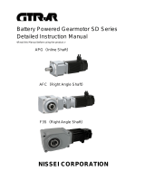
Bag and Cage Installation
1. Lower the bottom of the bag through
the hole in the tubesheet.
2. Fold the snap band (bag top) to insert
it into the tubesheet hole.
3. Fit the groove of the snap band to the
edge of the tubesheet and allow the
band to snap into place.
4. Slide the cage into the bag until it
rests on the tubesheet.
5. Check the fit of the snap band. It
should fit securely all around with no
wrinkles in the snap band. The top of
the bag should be above the tubesheet approximately 3/8”.
Optional Grounding Strip
If the bags are equipped with a grounding strip, fold the wire over the top of the bag and down its
side prior to fitting in the tubesheet. The wire should be between the bag cuff and the tubesheet as
shown in the illustration.
STAINLESS STEEL SNAP BAND
TUBESHEET TUBESHEET
CAGE TOP
WIRE CAGE
GROUND WIRE PLACED
BETWEEN BAG CUFF
AND TUBESHEET

FAX 402-245-5196 www.airlanco.com
7
800-500-9777
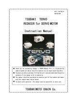
Cartridge Filter Installation
TUBESHEET
SEAL CHANNEL
CARTRIDGE FILTER
Pleated cartridge filters have a pliable polyurethane top flange that is inserted into the tubesheet
hole and snapped into place as shown in the illustration above. To remove, push the filter element
through the tubesheet hole and let it fall into the hopper. Retrieve dirty elements from the hopper
access door.
CAUTION: Cartridges may hang up on vortex breakers
in filter inlet during removal.

FAX 402-245-5196 www.airlanco.com
8
800-500-9777
RLP/MP Cage installation to “back” side of support channels
On smaller RLP/MP filters it is difficult to get the cages to the back side of the reverse air fan
support channels after the filter has been assembled. Before placing any bags or cages in any of
the tubesheet holes, locate a tubesheet hole relatively below the front support channel. Angle the
cage as shown below in first two figures down the tubesheet hole to get the cage between the front
and back support channels.
Locate a second hole relatively below the back support channel. Angle the cage as shown above
down the tubesheet hole to get the cage to the back side of the support channels. Stack all the
cages on the back side until installation.
Next, install bags and cages under the support channels. Finally, install the rest of the bags on the
back side and front side of the support channels working from the back to the front. See page 6 for
instructions on installing bags and cages to the tube sheet.
ACCESS DOOR
FRONT SUPPORT CHANNEL
BACK SUPPORT CHANNEL
CAGE
REVERSE AIR
FAN
TUBESHEET HOLES
ACCESS DOOR
CAGE
REVERSE AIR
FAN
TUBESHEET HOLES
FRONT SUPPORT CHANNEL
BACK SUPPORT CHANNEL
ACCESS DOOR
CAGE
REVERSE AIR
FAN
TUBESHEET HOLES
FRONT SUPPORT CHANNEL
BACK SUPPORT
CHANNEL
ACCESS DOOR
CAGE
REVERSE AIR
FAN
TUBESHEET HOLES
FRONT SUPPORT CHANNEL
BACK SUPPORT CHANNEL

INSTALLATION AND MAINTENANCE INSTRUCTIONS
Explosion Vents
704 S. 10th Street ∙ P.O. Box 610 ∙ Blue Springs, Missouri 64013-0610 U.S.A. ∙ (816) 229-3405 ∙ www.fike.com
06-308-1
WARNING
Read these instructions carefully and completely before
attempting to unpack, install or service the explosion vent.
Handle the explosion vent with extreme care. DO NOT
bend, poke, or in any way distort the explosion vent.
Do not locate vent assembly where personnel are
exposed to the vent or the area above or in front of the
vent, as they may be injured by the release of pressure,
flame, noise, particles, and/or process material.
Locate the explosion vent so that the discharge does not
ignite other combustibles, resulting in an ensuing fire or
secondary explosion.
Interfacing equipment and/or machinery must also be
protected.
Flow arrows on round explosion vent tags, or explosion
vent tag for square and rectangular vents must be directed
to the atmospheric side of the process. Provisions shall
be made to prevent personnel from standing or walking on
vents, as they risk falling through.
The vent opening is to be left free and clear. Nothing, i.e.
goods or products, is allowed to obstruct the vent area as
this will decrease vent efficiency.
Install the enclosed DANGER sign in a conspicuous
location near the zone of potential danger.
GENERAL
An explosion vent is a pressure relief device, designed to give
an instantaneous opening at a predetermined pressure. Its
purpose is to protect the equipment from excessive pressures
caused by dust or gas deflagrations.
INSPECTION/PREPARATION
WARNING: Always handle the explosion vent with extreme
caution. Handle the explosion vent by its edges only. Damage
to the functional area (center) or seat area of the explosion
vent may adversely affect the performance of the explosion
vent. Read the explosion vent tag completely before installing
to confirm that the size and type are correct for your system.
1. Carefully remove the explosion vent from its packaging
container.
2. Inspect the explosion vent for damage.
3. If foreign material is present, carefully clean the explosion
vent with a solvent that is compatible with your media.
4. Two personnel are recommended for handling of all vents
larger than 24” x 30” (600 x 1000 mm) (rectangular) and
30” (800 mm) (round) or larger.
5. CV-SF vents require vent frames with back-up bars to
properly function (consult Fike for design requirements).
INSTALLATION - OPEN DISCHARGE
WARNING: The vent opening should be left free and clear. Do
not insulate any part of the explosion vent or frame without
consulting Fike.
IMPORTANT: When explosion vents are installed horizontally,
the use of drainage/weep holes in the holddown frame is
required.
1. Use base/inlet of explosion vent frame as a template to
indicate placement of explosion vent on the vessel or duct
to be protected.
2. Cut the vessel or duct opening to the marked size. The
marked size should match the size identified on the vent
tag.
3. Weld or bolt the inlet angle frame to the vessel or duct.
IMPORTANT: The explosion vent frame must be installed such
that the seat area is flat and bolt holes remain perpendicular
(square and rectangular vent frames) or circular (round vent
frames).
4. If sealing is a particular concern due to the nature of the
process, apply a process compatible silicone sealant or
gasket to provide seal between explosion vent and inlet
frame.
5. If using a gasket, select a gasket material that is
compatible with the process, with a suggested thickness of
1/8" (3.2 mm) maximum. The gasket is to have the same
inside diameter and outside diameter as the explosion
vent frame.
6. Install the explosion vent and outlet flange aligning the bolt
holes. DO NOT force the explosion vent hole alignment.
7. Apply light oil to the threads and install the nuts and bolts
hand tight.
8. Torque each bolt to the value identified on the explosion
vent tag.
CAUTION: The torque values should not be exceeded as this
may cause failure of the bolt and/or damage to the vent.
INSTALLATION – WITH FLAMQUENCH II SQ (FQIISQ)
For additional information, refer to FQIISQ installation
instructions, E06-085.
WARNING: The vent opening should be left free and clear. Do
not insulate any part of the explosion vent or frame without
consulting Fike.
1. Use base/inlet of explosion vent frame as a template to
indicate placement of explosion vent on the vessel or duct
to be protected.

704 S. 10th Street ∙ P.O. Box 610 ∙ Blue Springs, Missouri 64013-0610 U.S.A. ∙ (816) 229-3405 ∙ www.fike.com
Copyright © Fike Corporation All Rights Reserved.
P/N 06-308-1-6 October, 2011 Specifications are subject to change without notice.
2. Cut the vessel or duct opening to the marked size. The
marked size should match the size identified on the vent
tag.
IMPORTANT: The FQIISQ uses an alignment hole feature to
ensure proper orientation of the hinge of the explosion vent.
The alignment hole must be included on the mounting frame so
the explosion vent and FQIISQ can be mounted in only the
prescribed orientation. Consult factory for FQIISQ bolting
pattern.
3. Weld or bolt the inlet angle frame to the vessel or duct.
IMPORTANT: The explosion vent frame must be installed such
that the seat area is flat and bolt holes remain perpendicular
(square and rectangular vent frames).
4. Install gaskets on both sides of the explosion vent. Select
a gasket material that is compatible with the process, with
a suggested thickness of 1/16" (1.5 mm) maximum. The
gasket is to have the same inside diameter and outside
diameter as the explosion vent frame.
5. Install the explosion vent and outlet flange aligning the bolt
holes. DO NOT force the explosion vent hole alignment.
6. Apply light oil to the threads and install the nuts and bolts
hand tight.
7. Torque each bolt to the value identified on the explosion
vent tag.
CAUTION: The torque values should not be exceeded as this
may cause failure of the bolt and/or damage to the vent.
BURST INDICATOR
The explosion vents can have as an option an integrated
electric burst indicator designed for intrinsically safe service.
Refer to Burst Indicator Instructions / Drawing for electrical and
dimensional specifications.
CAUTION: Unacceptably high voltage or currents will
permanently damage the electrical system and the use of a
non approved intrinsically safe power supply may even be the
eventual ignition source of a dust or gas explosion. All burst
indicators must be installed in an intrinsically safe circuit which
conforms to the applicable national standard.
WARNING: Do not bend the electrical cable at any angle at a
distance of less than 8 inch (20cm) from the mechanical
bracing part and do not lift the explosion vent by the electrical
cable, as this may damage the electrical circuit.
WARNING: The maximum torque values as mentioned on the
nameplate must not be exceeded as this will permanently
damage the electrical circuit.
MAINTENANCE
The explosion vent is maintenance-free due to its basic design
and concept. Periodic visual inspections should be performed
in accordance to the operating parameters and severity of
service. All operational system parameters should be
observed as a standard maintenance practice. The explosion
vent must be replaced if they appear damaged, corroded, or
leaking.
NOTE: Severe service is defined as rapid changes in pressure,
high pressure, high temperature, or corrosive process.

FAX 402-245-5196 www.airlanco.com
11
800-500-9777
Operation
Proper startup and shutdown procedures are very important in the successful operation of a bag
house filter. A typical ambient air dust collection system should follow this sequence of operation.
1. Start the dust removal system that transfers collected material from the filter
hopper. This could include rotary airlocks, pneumatic conveying equipment, etc.
This step is not applicable for Style II bin vent filters.
2. Start the bag house cleaning mechanism. Before starting additional equipment, let
the cleaning mechanism run long enough to allow the filter temperature and
humidity to stabilize with ambient conditions and to remove any material that may
have been left from the previous day’s operation. This is most important in high
humidity climates.
3. Start the main system fan.
4. Start the operation or process where dust is being collected.
Reverse the order of the above sequence to shut down the bag house.
1. Shut down the operation or process where dust is being collected.
2. Shut down the main system fan.
3. Shut down the bag house cleaning mechanism after allowing the collected material
to be discharged from the collector.
4. Shut down the dust removal system that transfers material from the filter hopper
(not applicable for Style II bin vent filters).

FAX 402-245-5196 www.airlanco.com
12
800-500-9777
Maintenance
Very little maintenance is required to achieve maximum efficiency and life from your AIRLANCO
filter.
The following items should be periodically serviced:
Lubrication
All bearings in the cleaning mechanism and fan drive should be lubricated periodically on a
schedule that corresponds with other equipment in your facility. Bearings should be filled with
quality grease at least once a year. Avoid forcing an excessive amount of grease into the bearing
as this may cause seal damage. The roller chain drive should be kept tight enough so that the
chain cannot “climb the sprocket” and should be oiled lightly once a month.
Cleaning and Repair
The external portion of this unit should be treated as any other metal surface that is subject to
corrosion. Clean periodically and repaint damaged surfaces when needed to prevent corrosion.
Dust may enter the clean air plenum through a leaking or broken bag. Remove accumulated dust
from clean air plenum immediately. Dust in the clean air side of a filter bag will reduce the life and
performance of the bag.
Bags
Filter bags do not require any periodic maintenance. However, at some point the bags will require
replacement. This will be indicated by persistent high differential pressure across the bags and is
not accompanied by any other change in the operating parameters of the system. Many factors
affect the life of filter bags. Refer to the section on troubleshooting (page 18) if low bag life or
persistent wear problems are evident.
Rotary Valve (Airlock) See airlock operation and maintenance manual.
Screw Conveyor
The roller chain drive should be kept tight enough so that the chain cannot "climb the sprocket" and
should be oiled lightly once per month. The auger bearings have been factory pre-lubricated with
high quality grease and for normal conditions of service require no further lubrication. Periodic
lubrication may be advisable when service is abnormal with respect to speed, temperature,
exposure to moisture, dirt, or corrosive chemicals, or where extremely long life is required. Remove
pipe plug and replace with a standard grease fitting to lubricate.
Speed Reducer (Arm Drive)
For maintenance and lubrication requirements, refer to the included Ohio Gear Ironman manual.

FAX 402-245-5196 www.airlanco.com
13
800-500-9777
Magnehelic Gauge Operation
TOP PLENUM
TUBESHEET
HIGH PRESSURE
DIRTY AIR HOUSING
(BAG HOUSE)
BAGHOUSE
LOW PRESSURE
CLEAN AIR
(TOP PLENUM)
ZERO SET
DISCHARGE CONE
CLEAN AIR
EXHAUST
DIRTY AIR
INLET
FILTER BAGS
OR CARTRIDGES
FILTERED MATERIAL
DISCHARGE
1/4" TUBING
2
46
8
10
0
MAGNEHELIC
The Magnehelic® gauge is used to measure the differential pressure between the clean gas side
(top plenum) and the dirty gas side of the baghouse. It measures the force required to pass air
through the filter media.
Normal pressure drop for a filter will fall in the range of 1 to 5 inches of water after the elements
establish a dust cake. The differential pressure reading will increase as the elements get dirty.
Eventually, the dust cake must be removed from the filter element surface or air flow will fall to
unacceptable levels.

FAX 402-245-5196 www.airlanco.com
14
800-500-9777
Troubleshooting RLP Filters
The RLP is a continuous self-cleaning filter. A
flow of low pressure air from a centrifugal fan is
directed into each bag at periodic intervals. Air
is distributed to each row of filter bags through a
rotating arm equipped with nozzles. Refer to
drawing 10532 on page 19 for an illustration of
the cleaning mechanism. The low pressure
reverse flow of air from the fan will gently clean
each bag. A percentage of the dust cake will fall
away from the bag into the filter hopper. It is
normal for some of the dust to re-entrain onto
the bag. The rotating distribution arm turns at
approximately 1 RPM. The slow speed virtually
eliminates wear to moving parts and seals. A ¾
HP gearmotor turns the arm with a chain drive.
Troubleshooting the RLP is a straight forward
process, but does require some preliminary
information to simplify the process. Complete
the worksheet on the following page before
calling AIRLANCO (800-500-9777) for service.
/