Page is loading ...

1/4
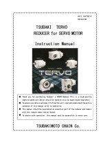
Tsubaki
TM Series
Instruction Manual
Thank you for purchasing the Tsubaki TM Series.
In order to fully realize the characteristics of this
reducer, please read this manual carefully and
use it for installation and inspection.
Please ensure that this manual is delivered to the
customer who will use the reducer.
1. When purchased
First inspect the following items upon receipt of your reducer.
(1) After unpacking the reducer, does the model number, reduction
ratio, shaft arrangement, and motor capacity listed on the
nameplate match your order?
(2) Visually inspect for damage sustained during transport.
(3) Make sure there are no loose screws or bolts.
If you find any problems, please contact the dealer where the
reducer was purchased.
2. Installation
(1) Transport
When transporting the reducer, never hook wires or slings to the
input/output shafts. (The reducer may slip off and be damaged or
the shafts may be scratched and sprockets or other components
can no longer be attached.)
(2) Installation
The area of installation should have an ambient temperature of 5
to 40°C, be well-ventilated, low in humidity, and have little or no
dust.
Do not use the reducer in locations with corrosive liquids or gases,
or in flammable or explosive locations. If the reducer is to be used
outdoors, furnish a cover or similar protection to avoid direct
exposure to rain.
(3) Mounting
Use a strong and flat mounting stand and securely mount the
reducer to it.
(3)-1. Using mounting feet
Loosen two of the four hex cap bolts on the reducer
and use those to promptly attach the supplied feet.
The TM10E does not have fixing bolts for combining
the housing. The 13E, 16E, and 22E have fixing
bolts, but after they are removed, there is a risk of
lubrication oil leaking or damage due to rough
handling. Use caution.
Mounting examples
(3)-2. Mounting directly (flange mounting)
When mounting the reducer directly to the floor or wall, take
note of the following:
1) The oil seal and cap protrude about 1 mm from
the mounting surface. Leave at least 1 mm of
clearance between the reducer and mounting
surface as shown in the following figure.
2) After removing the four mounting bolts, promptly
install the reducer. Handle with care to prevent
lubrication oil from leaking.
Input shaft
Output shaft
Output shaft
Input shaft
Output shaft
Input shaft
Output shaft
Input shaft
Output shaft
Input shaft

2/4
Unit: mm
(3)-3. Bolt sizes and tightening torque
Unit: mm
Size Bolt size (mm)
Tightening torque (N·m)
(kgf·m)
TM10E
M6 x 60 (x4) 4.9 to 5.9
{0.50 to 0.60}
TM13E
M8 x 80 (x4) 12 to 14
{1.2 to 1.4}
TM16E
M10 x 90 (x4) 24 to 27
{2.4 to 2.7}
TM22E
M10 x 100 (x2)
24 to 27
{2.4 to 2.7}
M10 x 120 (x2)
24 to 27
{2.4 to 2.7}
Bolt pitch width
Unit: mm
A B
TM10E 57 76
TM13E 71 96
TM16E 88 111
TM22E 115 150
(3)-4. Connection with driven machine
When connecting the reducer, use caution as there is a risk of
damage to the input/output shaft bearings if the sprockets and
gears are tapped strongly. Accurately center the belts and chains
and do not subject them to an overhanging load that exceeds the
specified value.
3. Lubrication
1) The reducer is shipped filled with premium quality lubrication oil
(Mobil Cylinder Oil 600W) and should be used as is. In most
situations the lubrication oil does not need to be replaced or
topped off, but if it is replaced every 10,000 hours, this will
increase the service life of the reducer.
2) Replace the lubrication oil according to the following procedure.
・ Remove the plugs at the center of the worm shaft on both
sides of the housing.
・ Turn the housing on its side and drain the lubrication oil.
・ When the lubrication oil is fully drained, rinse the interior of
the housing by flushing it with oil.
・ Use a dropper and fill with lubrication oil from the oil filling
port.
・ Do not mix the oil with other brands.
Oil volume outline
Type 10E
13E
16E
22E
Oil volume (ml)
80 170
290
520
4. Operating precautions
1) Inspecting prior to use
• When you have finished installing the reducer, check that the (1)
direction of rotation is correct, (2) the bolts are not loose, and (3)
the reducer is properly connected to the driven machine.
• In order to prevent accidents before they happen;
Make sure the equipment incorporates failsafe measures due to
the use of the reducer, or in the event the reducer malfunctions.
2) Load
Loading the reducer above its rated capacity can affect its life
and result in damage. Use the reducer within the allowable torque
value in the catalog.
3) Verification after operation starts
Verify the following after starting production:
a) There is no abnormal vibration or noise.
b) There is no shock.
c) The temperature is not unusually high.
• The reducer may generate heat during the first two or three days
of operation. This is expected and does indicate a problem.
However, if the reducer's housing surface temperature exceeds
93°C, it could indicate insufficient capacity. Please contact us.
5. Maintenance precautions
1) Maintenance
• When performing maintenance, wear suitable clothing and use
protection including safety glasses, gloves, safety shoes, etc.
• To prevent secondary accidents, keep the surrounding area safe
and tidy.
• Always turn the power off and wait for the machine to come to a
full stop. Also, use lock-outs to prevent unintentional power
supply.
• The reducer reaches extremely high temperatures during
operation. Do not touch with your bare hands.
• Read and follow labor safety codes and standards.
2) Maintenance items
Make daily inspections using appropriate measuring instruments
with the following procedures. Take note of operating conditions
when performing maintenance.
Item Details
Noise Is the noise louder than usual? Are
there unusual periodic noises?
Vibration Are there any unusual vibrations?
Temperature rise
Is there an unusual increase in
temperature? (A rough guide is a
temperature increase around 50°C)
Oil leakage
Are there any leakages from the
connection points on the reducer, oil
seals, or caps?
Note) (1) When a problem occurs, immediately stop operation and
perform a detailed inspection.
(2) If the cause is unclear or repairs are not possible, consult
the dealer where the reducer was purchased.
Model
number φD t
TM10E 30 1
TM13E 35 1
TM16E 35 1
TM22E 72 0.5
Span B
Span A

3/4
6. Internal construction
diagram
Example) TM16E internal construction
(1)
Housing (7)
Shim (13)
Parallel keyway II
(2)
WG worm (8)
Bearing (14)
Hex cap bolt
(3)
WG wheel (9)
Bearing (15)
Hex cap bolt
(4)
Output shaft B
(10)
Oil seal (16)
U nut
(5)
Input cap (11)
Oil seal (17)
Hex nut I
(6)
Output cap (12)
Parallel keyway II
(18)
Plug with hole I
7. Others
1) Type with motor (GCE)
For details about the motor section, refer to the instruction manual
for the motor. The following items are the couplings for connecting
the motor and reducer (Tsubaki E&M L jaw couplings).
Type 16GCE 22GCE
Coupling L070-S L090-S
2) Special specifications
Check the drawings when using the instruction manual.
Tsubaki E&M TM Series
Safety precautions
Thank you for your patronage.
In order to use this reducer safely, always observe the following
items.
●
An experienced technician should perform any work when handling
the TM Series. The content listed in this instruction manual must
also be carefully read and fully understood before using the reducer.
● Please ensure that this instruction manual is delivered to the
customer who will use the reducer.
● Carefully store the instruction manual so that it can be used at any
time before handling the reducer.
● The degree of harm and damage that can be expected to occur
when the reducer is mishandled is essentially classified into the
ranks of "DANGER" and "CAUTION", and these are indicated in the
instruction manual. The definitions and indications are as follows.
DANGER
This indicates the possibility that a
dangerous situation may occur, resulting
in death or serious injury if the reducer is
mishandled.
CAUTION
This indicates the possibility that a
dangerous situation may occur, resulting
in a moderate or light injury, or resulting
in only physical damage, if the reducer is
mishandled.
Depending on the situation, even items listed under CAUTION may
result in serious consequences.
Both indicate important content that must always be observed.
DANGER
(Overall)
• Work to transport, install, run tubing, wire, run/operate, and
maintain/inspect the reducer must always be performed by a
technician with specialized knowledge and skills. Otherwise
there is a risk of injury and damage to equipment.
• When the reducer is installed in equipment to transport
people, always install protective devices for safety on the
equipment side.
Otherwise there is a risk of accidents due to runaway
equipment and damage to equipment.
• When the reducer is used in lift equipment, always install
safety devices to prevent drops on the equipment side.
Otherwise there is a risk of accidents and damage to
equipment due to the lift falling.
(Installation)
• When hoisting the reducer to transport it, do not enter the
area underneath it. Otherwise there is a risk of accidents due
to the reducer falling.
(Operation)
• During operation, do not get near or touch any rotating bodies
(shafts or other parts). Otherwise there is a risk of being
caught in those parts resulting in injury.
(Daily inspection and maintenance)
• In inspection and maintenance during operation, do not touch
any rotating bodies (shafts or other parts). Otherwise there is
a risk of being caught in those parts resulting in accident.
• When entering the inside of the product to inspect it while
stopped, first confirm that the rotation of the motor and the
driven machine has stopped, and sufficiently cool the inside of
the product, and then you must work while ventilating the
interior. While performing the inspection work, arrange
personnel for confirming safe working conditions on the
exterior, and always confirm safety with the worker. Be aware
that the product interior is slippery from lubrication oil and take
sufficient safety precautions. Otherwise there is a risk of
accidents.
CAUTION
(Overall)
• Do not use the reducer outside of the specifications listed on
the TM Series nameplate or the reducer specifications in
manufacturing specification document. Otherwise there is a
risk of injury and damage to equipment.
• Do not insert fingers or objects into the openings on the TM
Series. Otherwise there is a risk of injury and damage to
equipment.
• Do not use the TM Series when damaged. Otherwise there is a
risk of injury and damage to equipment.
• Do not remove the nameplate.
• Alterations to the reducer by the customer are not covered by
the warranty and Tsubaki E&M assumes no responsibility for
them.
(Upon receipt of your reducer)
• Check the orientation of the packaging and open it. Otherwise
there is a risk of injury.
• Make sure the model number of the unit delivered matches
your order. If the wrong reducer is installed, there is a risk of
injury and damage to equipment.
(Transport)
• Use caution when transporting the reducer as it is dangerous if
it drops or falls over. If the TM Series has lifting rings, always

4/4
use those lifting rings. However, after the reducer is installed in
the machinery, do not hoist the machinery itself with the lifting
rings. Before hoisting the reducer, check the TM Series weight
on the nameplate, packaging, external diagram, catalog or
other documents, and do not suspend a reducer that exceeds
the weight rating of the lifting rings. Otherwise there is a risk of
damaging the lifting rings, injury from the reducer falling over,
and damage to equipment.
(Installation)
• Do not place obstructions around the TM Series that will
interfere with ventilation. This will hinder cooling and may
result in burns or a fire due to abnormal overheating.
• Do not get on the TM Series or hang from it under any
circumstances. Otherwise there is a risk of injury.
• Do not touch the keyways on the ends of the shafts of the TM
Series with bare hands. Otherwise there is a risk of injury.
• For equipment that is averse to greasiness such as food
machinery, take precautions for an accidental oil leak due to
breakdown or service life and install damage prevention
equipment such as an oil pan. Otherwise there is a risk the
reducer may become faulty due to an oil leak.
(Connection)
• When connecting the TM Series to a motor and the driven
machine, pay careful attention to centering, belt tension, and
the parallelism of the pulleys. When directly connected, pay
careful attention to the accuracy of the direct connection.
When belt driven, correctly adjust the belt tension. Before
operation, ensure that the tie bolts for the pulleys and
couplings have been fully tightened. Otherwise there is a risk
of injury and damage to equipment due to flying debris.
• Install a cover so that rotating components will not be touched.
Otherwise there is a risk of injury.
• When the TM Series will rotate independently, remove the key
that is temporarily installed to the output shaft. Otherwise there
is a risk of injury.
• Check the direction of rotation before connecting the reducer
to the driven machine. There is a risk of injury and damage to
equipment by mistaking the direction of rotation.
(Operation)
• During operation, the TM Series reaches high temperatures.
Use caution not to touch the reducer with your hands or body.
Otherwise there is a risk of burns.
• When a problem occurs, immediately stop operation.
Otherwise there is a risk of injury.
• Do not use the reducer with a load that exceeds the rated load.
Otherwise there is a risk of injury and damage to equipment.
• Do not loosen the oil plugs during operation. Otherwise
lubrication oil may spray out resulting in burns.
• When running the reducer in reverse, first stop it, and then run
it in reverse. Forward and reverse operation by plucking may
damage the TM Series and the driven machine.
(Daily inspection and maintenance)
• Change the lubrication oil and grease according to the
instruction manual. Always use the type of oil recommended
by the manufacturer. Otherwise there is a risk of damage to
equipment.
• The surface of the TM Series reaches high temperatures, so
do not touch it bare hands. Otherwise there is a risk of burns.
• Do not change the lubrication oil or grease during operation or
immediately after stopping. Otherwise there is a risk of burns.
• Diagnose problems that occur based on the instruction
manual. Do not operate the reducer until the cause of the
problem has been determined and action has been taken.
(Disassembly/assembly)
• Repair, disassembly, and assembly should always be
performed by a specialist. Otherwise there is a risk of injury
and damage to equipment.
(Disposal)
• The TM Series and its lubrication oil should be treated as
general industrial waste.
Limited Warranty
Tsubaki E&M Co.: hereinafter referred to as “Seller”
Customer: hereinafter referred to as “Buyer”
Goods sold or supplied by Seller to Buyer: hereinafter referred to as “Goods”
1. Warranty period without charge
18 months effective the date of shipment or 12 months effective the
first use of Goods, including installation of Goods to Buyer’s
equipment or machine - whichever comes first.
2. Warranty coverage
Should any damage or problem with the Goods arise within the
warranty period, given that the Goods were operated and
maintained according to the instructions provided in the manual,
Seller will repair and replace at no charge once the Goods are
returned to the Seller.
This warranty only covers individual Goods supplied by the Seller to
the Buyer and therefore does not include the following:
(1) Any costs related to the removal or re-installation of Goods from
the Buyer’s equipment or machine to repair or replace parts.
(2) Cost to transport Buyer’s equipment or machines to repair
facility.
(3) Costs to reimburse any profit loss due to any repair or damage
and consequential losses caused by the Buyer.
3. Warranty with charge
Seller will charge for any investigation and repair of Goods (even
during the warranty period without charge) caused by:
(1) Improper installation by failing to follow the instruction manual.
(2) Insufficient maintenance or improper operation by the Buyer.
(3) Incorrect installation of Goods onto other equipment or
machines.
(4) Structure change of the Goods by any modifications or
alterations by the Buyer.
(5) Any repair by engineers other than the Seller or those designated
by the Seller.
(6) Operation in an inappropriate environment not specified in the
manual.
(7) Force Majeure or forces beyond the Seller’s control such as a
natural disaster and injustices committed by a third party.
(8) Secondary damage or problems incurred by the Buyer’s
equipment or machines.
(9) Defective parts supplied or specified by the Buyer.
(10) Wear, tear or deterioration of parts including bearings and oil
seals.
(11) Loss or damage not liable to the Seller.
For inquires related to this instruction manual, please contact customer
service.
Customer service Tel: (0120) 251-602, Fax: (0120) 251-603
Headquarters Factory Kotari Kuresumi 1-1, Nagaokakyo, Kyoto, Japan
617-0833
Hyogo Factory Asazuma-cho 1140, Kasai, Hyogo, Japan 679-0181
Okayama Factory Niinohigashi 1515, Tsuyama, Okayama, Japan 708-1205
Nov. 1, 2013 Bulletin. No. GP25FE
URL http://www.tsubakimoto.jp
Tsubaki E&M
Co.
/