Page is loading ...

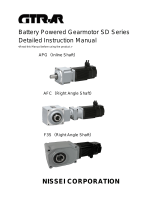
Battery Powered Gearmotor V Series
Instruction Manual
<Read this Manual before using the product.>
VG (Inline Shaft)
VH (Right Angle Shaft)
VF3 (Right Angle Hollow Bore)
(Right Angle Solid Shaft)
NISSEI CORPORATION

Thank you very much for purchasing the GTR-AR series.
●
●
: The symbol ● indicates “what you must do.”
Specific “do” item is depicted in the circle. (The example on the left shows “Ground Connection.”)
Danger
If the product is used in a device such as a personnel transport device, make sure to install a protective device
for safety purposes. Failure to implement safety measures may result in personal injury,death, and/or damage
to the device.
If the product is used in an elevator, install a safety device on the device side to prevent it from falling. Failure
to implement safety measures may result in personal injury,death, and/or damage to the device due to the
falling of the elevator.
Do not use the product in an explosive environment.
Failure to follow this precaution may result in explosions, ignition of fire, fire, electric shocks, injuries, and/or
damage to the device.
Do not change the wiring while the product is energized. Failure to follow this precaution may result in fire,
electric shock, and/or damage to the device.
Extents of hazard/damage expected to occur in the case of inept handling are basically classified and indicated
into ranks of “Danger”, “Warning” and “Caution” in this Instruction Manual. The definitions and indications are
as follows:
Danger Cases where it is expected that a degree of danger is extremely high such that inept handling
possibly causes a dangerous situation to occur, which may lead to death or serious injury.
Caution Cases where inept handling possibly causes a dangerous situation to occur, from which it is
expected a medium degree of injury or minor one may be incurred.
Even the items described in “Caution” may lead to a serious accident depending on situation. Be sure to observe
every instruction which deals with important contents.
Warning Cases where inept handling possibly causes a dangerous situation to occur, which may lead to
death or serious injury.
Introduction
Safety precautions
Be sure to carefully read the contents described in this Instruction Manual and to master how to use the product
correctly before using it.
: The symbol △ indicates “what you should pay attention to.”
(The example on the left shows “Electric Shock Hazard.”)
: The symbol ○ indicates “what you must not do.”
Specific “don’t” item is depicted in the circle. (The example on the left shows “Don’t Disassemble.”)

Caution
The product must be transported correctly in accordance with its weight.
When transporting the product, do not hold the product by the cable or output shaft. Failure to follow this
precaution may result in damage to the equipment or injury.
Do not overload/overstack the products. Failure to follow this precaution may result in injury and/or equipment
failure.
Warning
When replacing a product equipped with holding brake, make sure to secure the machine side part of the product.
Failure to follow this precaution may result in injury and/or damage to the device due to device falling down.
When performing trial operation, fix the product in place and disconnect it from the machine. Failure to
observe this precaution may result in injury.
Never use the product in a location where the motor may be exposed to splashes of water, corrosive substances, flammable
gas, and/or flammable objects. Failure to follow this precaution may result in fire or accidents.
The operators in charge of transportation, installation, wiring, operation, handling, maintenance, and inspection should have
enough knowledge and technical skill related to the product. Failure to follow this precaution may result in explosion, ignition
of fire, fire, electric shock, injury, and/or damage to the device.
Do not repair, disassemble or remodel the product. Failure to observe this precaution may result in injury, fire,
electric shock or burns.
When the operation has stopped due to the occurance of error or activated safeguards, do not re-start the operation until the
causes of error are determined and countermeasures are taken.
Failure to follow this precaution may result in damage to the equipment, injury, fire, electric shock and/or burns.
The equipment might suddenly start operating after recovering from a power failure. Make sure not to go near
the equipment. Failure to follow this precaution may result in injury.
Do not put any object that may prevent air from being circulated around the product. Failure to follow this
precaution can cause abnormal overheating of the product. It may result in fire or burns.
Be careful not to cause damage to the cable nor pull it strongly. Failure to follow this precaution may result in
injury, fire and/or electric shock.
Do not stand on or place any heavy object on the product. Failure to follow this precaution may result in injury.
Do not touch the gearmotor or driver when the power is on or immediately after turning off the power, as their surfaces may
be hot. Failure to follow this precaution may cause burns.
When operating the gearmotor with our driver, please use the specified combination.
Failure to follow this precaution may result in fire and/or damage to the equipment.
When handling the gearmotor. be careful with the sharp edges/points of the device. Failure to follow this
precaution may result in injury.
Fix the gearmotor firmly in place. Failure to follow this precaution may result in damage to the equipment or
injury.
If there is possible risk of dangerous movement due to external forces (such as gravity) during a power outage and/or error,
the brake on the gear motor alone cannot ensure safety. For such situations, please be sure to add external brakes to
ensure safety.
Never perform operations with wet hands. Failure to follow this precaution may result in electric shock.
Immediately stop the operation if there is any abnormality. Failure to follow this precaution may result in fire
and/or injury.
Do not put any combustible material near the product. Failure to follow this precaution may result in fire.
Operate the product under the conditions specified in this instruction manual. Failure to follow this precaution
may result in damage to the equipment or injury.

■
CCC Certification
○:
CCC certified
ー:
Not subject to CCC certification
○
CCC
ー
ー
ー
ー
Motor power (W) 50 100
Voltage (V) 12 24 12 24 48
From the mandatory product certification implementation rule CNCA-C04-01:2014, our 48V Brushless DC
gearmotors are subject to CCC certification.(CCC certification does not apply to power supply voltage of 36V or
less.)
Products with a CCC mark on the nameplate are CCC certified products.Please refer to the table below for the
compliance of the standards.
We have made every possible effort to make the contents of this Manual precise and clear. If there is anything that is unclear or
hard to understand, please feel free to contact us. Your comments will be greatly appreciated.
Important
Do not expose the product to strong impacts/shocks. Failure to observe this precaution may result in failure of
the product and/or injury.
Make sure that the gearmotor is correctly wired. Failure to follow this precaution may result in injury due to
damaged equipment.
When disposing of the product, dispose of it as a general industrial waste. Please follow local laws and regulations if any applies
and take care of the waste accordingly.
Do not touch the rotating part of the gearmotor. Failure to follow this precaution may result in injury.
In equipments like food machines, which must avoid oil or grease, furnish with protective devices like oil pan,
in order to protect from the oil leakage caused by failure or life of the manufactured products. Leaking oil may
cause defective products.
Caution
Notice
We shall assume no responsibility or liability for any troubles caused by use that violates the cautions this manual.
The contents of this Manual are subject to change without notice.
200 400
24 48 24 48
ー
○
ー
○

Table of contents
Introduction
Safety precautions
1. Before Using This Product
1-1 Names of parts and their functions
P.6
Gearmotor
1-2 Things you should check before use
P.6
Contents of the package
1-3 Information provided on nameplate
P.7
2. Connection Method and Installation
2-1 Connection method
P.8
2-2 Motor signal line and power line
P.9
Signal line colors and functions
Connector pin configuration
Motor power line colors and descriptions
Brake lead wire colors and voltage specifications
2-3 Installation
P.10
Installation location
Installation direction
Mounting method
Tightening torque
2-4 Connecting with other equipment
P.11
When directly connected
Attaching Chains, V-Belts, Gears, etc.
Installing or removing the hollow bore
3. Specifications and Performance
3-1 Motor and electromagnetic brake specifications
P.19
Motor specifications
Electromagnetic brake specifications
3-2 Range of use of gearmotor
P.20
3-3 When making a driver
P.22
4. Maintenance, Service Life, and Inspection
4-1 Maintenance and service life
P.23
4-2 Periodic inspection
P.23
4-3 Brake gap adjustment method
P.23
Adjustment method
50 W
100 W, 200 W, 400 W
Toothed lock washer nut mounting method
5. Warranty
P.25

1. Before Using This Product
1-1 Names of parts and their functions
■
Gearmotor
Brake lead wire Motor signal line Motor power line
Output shaft
Gearhead
Brake Motor Bracket Foot
* Its appearance differs according to classification by mount form and motor type.
1-2 Things you should check before use
■
Contents of the package
Check for the following items when unpacking the package.
(1) Is the information on the nameplate consistent with your order?
Model, reduction ratio, motor capacity, voltage,etc…
(3) Are there any loose nuts or screws?
(4) Contents of the package
a) Gearmotor……………………………………………………… 1 unit
b) Instruction Manual (abridged edition)
………………………
1 copy Surge protector
c) Surge protector (with brake only)
……………………………
1 piece Part Number: ERZV07D820
d) Optional parts
If there are any defects, or if you have any questions, please contact us
immediately.
(2) Are there any damaged parts due to an unexpected accident, etc.
during transportation?
6

1-3 Information provided on nameplate
■For 12V or 24V
■
For 48V
Model
Rated Voltage
IP Rating
QR code
Insulation class
Reduction ratio
Manufacturing No.
Model
Rated Voltage
Reduction ratio
Insulation class
IP Rating
QR code
Manufacturing No.
CCC mark
7

2. Connection method and installation
2-1 Connection method
■
Connect each device as shown in the figure below.
The length of the cords from the gearmotor is 500mm
■
Example of connecting to our driver
Note: The maximum extension length for the motor signal line, motor power line, and brake lead wire is 5 m.
Note:
PIease use the extension cord (Option) if you need to
extend the motor signal cord.
If it is extended by connecting optional extension cords, its
overall length must be 4.5 m or less (i.e. up to four
extension cords can be used).
Extension cords are not available for the motor power line
and brake lead wire.
Extend it to 5 m or less using cords with a diameter not
smaller than the specified wire diameter (P.19).
Make the motor power line as short as possilbe in order to
avoid deterioration of motor performance.
If the motor signal line is extended by connecting optional extension cords, its overall length must
be 4.5 m or less (i.e., up to four extension cords can be used).
The motor power line is not equipped with a round terminal. Such terminal must be prepared by the
user.
Brake lead wire [0.3 m AWG20]
(with brake only)
* Shipped with the extension cord
having a connector on both ends.
Extension cord [1 m]
Motor power line [0.5 m]
Motor signal line [0.5 m]
Low Voltage Brushless DC Gearmotor
Connected to ontrol unit
Connected to PC
Connection to battery
power supply
PC connection cable [1 m] (option)
I/O cable [0.3 m] (driver accessory)
Clamp filter
(option)
Motor signal line [0.5 m]
Motor power line [0.5 m]
Low Voltage Brushless
DC Gearmotor
Brake lead wire [0.3 m AWG20] (with brake only)
Connected to brake power supply
8

2-2 Motor signal line and power line
■
Signal line colors and functions
■Connector pin configuration
■
Motor power line colors and descriptions
■
Brake lead wire colors and voltage specifications
Green/ White
Green
Gray
Orange
Purple
Plug housing
Manufacturer
SXA-001T-P0.6
XAP-05V-1
J.S.T. MFG.
Line color
W-phase pole signal output (open collector)
GND
Function
Red
White
Black
Description
U-phase
V-phase
W-phase
Line color
Pole sensor power supply (15 V for our driver)
U-phase pole signal output (open collector)
V-phase pole signal output (open collector)
Wire color
Socket crimping terminal
Yellow
White
Orange
Voltage specification
12 V specification
24 V specification
48 V specification
Terminal #1 notch
Purple
Orange
Green
Green/White
Gray
9

2-3 Installation
■
Installation environment
Ingress protection rating
:
IP30
Ambient temperature
:
0
℃
to 40
℃
Ambient humidity
:
85%RH or less (no dew condition)
Altitude
:
1,000 m or lower
Atmosphere
:
A well ventilated place free from corrosive gas, explosive gas, vapor and/or chemicals.
Not to be exposed to water and direct sunlight.
The brake should not be exposed to water, powders, grease, and/or oil mists.
■
Installation direction
There are no limitations on its orientation. (Since it uses a grease lubrication system)
■
Mounting method
[1] Foot and Flange Mount:
Secure it to a vibration-free, machined flat surface (flatness 0.3 mm or less) using four bolts.
[2] Shaft Mount(Torque arm mounting):
Allow the driven shaft to support the weight of the reducer.
(Make sure that the torque arm isn't subjected to forces other than rotation reaction forces.)
■
Tightening torque for installation fixing bolts (reference value)
M16
5.5 M5 2.9 {0.3}
6.5 M6 4.9 {0.5}
8.5 M8 13 {1.3}
108 {11.0}
Tightening torque
(
mm
)
(
N
・
m
)
{(
kgf
・
m
)}
{1.3}
11 M10 25
22 M20 294 {30.0}
13 M12 44 {4.5}
15 M14 69 {7.0}
18
Mounting hole Bolt size
{2.6}
9 M8 13
10

2-4 Connecting with other equipment
■
When directly connected
Shaft center of the connecting machine
Shaft center of the reducer
●
An example of gear coupling
●
The δ and θ should be minimized as much as possible.
●
To attach the connecting devices (coupling, sprocket, pulley, gear, etc.) to the reducer shaft, be sure to
use specified keys and provide H7 or equivalent fit tolerance.
The δ and θ differ according to the type of coupling. Therefore, they should be within the allowable
value defined by the respective manufacturer.(Reference: In case of chain coupling, δ should be
within 2% of the roller chain pitch and θ should be within 1 (Degree) .)
Must be aligned in a straight line.
δ
11

■
Attaching Chains, V-Belts, Gears, etc.
(1) Shaft center of the connecting machine
Shaft center of the reducer
(2) Chain/V-belt tension
Gear engagement
(3) V-belt tension — If it is too tight, the bearing may become damaged.
Chain tension —
The tension of the chain should be correctly adjusted.
Correct
Incorrect
If it is too tight, the bearing may become damaged. High impact force may also
occur if it is too loose which would result in adverse effects on the reducer and
Must be set parallel to each other.
Must be at right angle to shaft center.
Application
●The tension of V-belt and chain are properly set, also pulley and sprocket are properly positioned.
Sprocket
Application
●The chain is too loose.
●The sprocket is positioned in the reverse direction so that the load point moves to the shaft edge.
12

■
Installing and removing the hollow bore
●
Attaching the Hollow Bore of the Reducer to the Drive Shaft
[1]
[2]
When used with uniform loads, a drive shaft tolerance of h7 is recommended.
Additionally, when dealing with impact loads or large radial loads, make sure they fit each other tightly.
The tolerance of the interior surface of hollow bore is designed to be H8.
[3] If the shafts are a tight fit, use a plastic hammer on the end of the hollow bore to insert it.
Fig. 1
(Customers need to provide their own spacer, nuts, bolts, keys and shaft bearings.)
[4]
[5] It is recommended that axial runout for the shaft be 0.05 mm or less at the shaft end.
If major wobbling occurs during operation, it may have a negative effect on the reducer.
●
Connecting Reducer to the Drive Shaft
[1] When there are steps on the drive shaft
Fig. 2: Attachment Using a Spacer and Retaining Ring
(Customers need to provide their own spacer, bolts, and retaining rings.)
Note:Be careful when tightening the bolt, as tightening it too much can distort the shape of the retaining ring.
For the length of the turn-stop key for the drive shaft, tolerance range H8 for the bore on the fixed side
is recommended.
Coat the drive shaft surface and bore surface with a lubricant (molybdenum disulfide) suitable to the
atmosphere in which they are used and connect the reducer to the drive shaft.
When doing so, be sure not to hit the casing. If you make a jig like the one in the diagram below, drive
shaft insertion will be easier.
Key
Bore
Tolerance Hollow Fixed-End
Bore
Spacer
Bolt
Shaft Bearing
Oil Seal
Nut
Drive Shaft
Fix the drive shaft between
pillow block bearings
Retaining Ring Bolt
Spacer
Drive Shaft
13

Fig. 3: Attachment Using an Endplate
(Customers need to provide their own endplates and bolts.)
[2] When there are no steps on the drive shaft
Fig. 4: Attachment Using a Spacer and Retaining Ring
(Customers need to provide their own spacer, positioning spacers, bolts, and retaining rings.)
Make sure there is a gap between the outer diameter of the spacer and the bore diameter of the hollow bore.
In addition, attaching the positioning spacer allows for smooth removal from the hollow bore.
(Refer to Fig.5, p.15 for more on removal from the hollow bore.)
If the fit is too tight and the outer diameter of the spacer is inaccurate, burning and axial runout of the drive
shaft and hollow bore can result.
The positioning spacer is used to position the reducer. It is not required if you know the length of the drive
shaft in advance.
Fix the drive shaft between
pillow block bearings.
Endplate
Bolt
Fix the drive shaft between
pillow block bearings.
Bolt
Spacer
Retaining Ring
Positioning Spacer
Drive Shaft
Drive Shaft
14

●
Recommended Sizes for the Fixing Elments of the Drive Shaft
Recommended Sizes for the Fixing Elements of the Drive Shaft(mm)
●
Drive Shaft Length
●
Drive Shaft Key Length
●
Removal from the Hollow Bore
35
However, look at the dimension leeway for spacers in the section
titled "Removal from the Hollow Bore."
Make sure the drive shaft reaches both ends of L1. (See figure at right.)
The length of the key should be at least 1.5 times the width of the
hollow bore.
Additionally, the key is inserted in such a position that at least half its
length is in L1. (See figure at right.)
Make sure there is room to spare between the casing and the hollow
bore.
If you make and use a jig like the one below, drive shaft removal will
be easier.
φ34.5
For the attachment of the hollow bore in general use, we recommend you to refer to the dimensions
shown on the right as a guide line for the strength when designing.
Hollow Bore Bolt
Size Outer
Diameter Spacer Dimensions C-Shaped Retaining
Ring for Holes
Hole Diameter Inner Diameter Width
M6 φ14.5 φ7 3 15φ15
φ11 5
φ25 M6 φ24.5 φ7 4 25
φ30 M8 φ29.5 φ9 5 30
φ35 M10
Bolt
Spacer
C-Shaped Retaining Ring
(The convex spacer prevents rotation)
Key 2
Spacer Cross Section
Key 1 Round Plate Retaining Ring
Spacer (with Tap) Bolt
(The drive shaft will slide out if this bolt is tightend.)
Fig. 5
(Customers needs to provide their own spacers, round plates, bolts and retaining ring keys.)
15

●
How to Install the Reducer
The Advantages and Disadvantages of Flange and Torque Arm Installation
●
Hollow Bore and Flange Installation
●
* The values in parentheses are intended for VF3F(right angle solid shaft).
Reduction Ratio
1/10 to 1/160
1/10 to 1/60
Motor Power
0.1 kW
0.2 kW
Frame No.
15 (18)
25 (22) φ8.6M10×P1.5
B 13
Torque Arm
Installation
Advantages Disadvantages
When the hollow bore is installed directly to
the flange of an application, it can cause
motor burn-out or bearing damage if it is off-
center, so be sure to center it properly.
There is an installation guide, as shown in
the diagram at the right.
The dimension tolerance for φA for the
installation guide is h7 in the case of VF3S.
The installation bolts are installed as shown
in the diagram at the right. Four bolts should
be used.
Flange Installation
●
Makes centering with the application easy.
●Fastening to the application only requires one detent.
●
Can be installed directly on the device.
●Saves space. ●Centering with the application is required.
●
Requires a torque arm.
●Requires space for installing a torque arm.
DA E
φ10.5 φ8.6
When attaching the mounting bolts, it is recommended to have the engagement of the bolt with
thread D or F be at least two times the screw size (bolt diameter).(i.e. For an M10, 20 mm or more
of thread engagement with D or F is recommended.)
φ14
25
φ16.5
φ12.5
C
39.5
Detailed diagram of tapped holes for VF3 flange mount installation (standard specification)
15.5
40
30 45.5
φ8.6
1835 (32)
30 (28) 1/10 to 1/60
1/80 to 1/240
1/80 to 1/240
0.4 kW
0.2 kW
0.4 kW
φ10.5 40.5M10×P1.5
58M16×P2 φ10.6 15.5M12×P1.75
F
38M10×P1.5 14.5φ10.5 25
25
Installation Bolts (4 Bolts)
Installation Guide
Application Drive Shaft
VF3S (Right Angle Hollow Bore)
Application Flange
16

•
•
•
(Reference value)
How to install the Torque Arm Detent Ⓐ part
[1] For normal/reverse rotation operation and unidirectional operation (intermittently).
■Fastening the Reducer and Torque Arm
<Bolt Size and Tightening Torque>
Bolt size Tightening torque N•m {kgf•m}
Install the the torque arm detent to the driven
machine side.
Because the torque arm sustains a reactive force
from rotation, consideration needs to be given to
impact loads particularly during startup and braking,
Bolts and plates that are sufficiently strong must be
used. It is best to use an optional torque arm.
To install the torque arm and reducer, fasten them
using spring washers and flat washers with the
installation bolts.
25
{
2.6
}
M12 44
{
4.5
}
M16 108
{
11
}
Fasten the torque arm detent so there is no looseness or wobble. When doing this, center the
detent hole with that of the application to make sure that no radial load (suspension load) is applied
against the driven shaft and hollow shaft of the reducer. (Refer to the diagram below.)
M10
Detent Ⓐpart
Driven machine
side
Application Torque arm
Flat washer
Bolt
Spring
washer
Nut Hole in the driven machine
Hole on the torque arm side
Application Torque arm
Bad example
Unreasonable force will be applied to the driven
17

[2] Unidirectional operation (consecutive)
(Refer to ”● Connecting Reducer to the Drive Shaft”.)
For unidirectional operation (consecutive) which has no frequent start-up torque applied, the torque
arm can be used without a detent. However, it is still necessary to fasten the driven shaft to the
If mounting has a looseness, impact may be
applied to the torque arm with each startup and
defects such as loosen bolts may occur.
If mounting without looseness are not allowed
for some reason, rubber bush or other cushion
materials shall be used between the torque arm
and the bolt as a protective measure.
Bolts with sufficient strength shall be used.
(Refer to the right diagram.)
Note)
In this case, it is necessary to provide sufficient clearance for looseness in both radial and thrust
directions for alignment between the application and detent. (Refer to the diagram below.)
Rubber bush or other
cushion materials
Application
Torque Arm
Flat Washer
Bolt
Spring Washer
Nut
Nut
Application Stepped Pin
Torque arm
Leave a gap.
Leave a gap to avoid
radial loads.
Stepped Pin
Torque Arm Hole
Example of Stepped Pin Usage
18

3.
Specifications and Performance
3-1
Motor and electromagnetic brake specifications
■
Motor Specifications
* The rated current values in the table above are values for the motor unit only (gearhead removed).
For gearmotor information, see p.20-21.
■
Electromagnetic Brake Specifications
Ambient Storage
Humidity (%RH)
Be sure to insert a Surge protector to protect the driver from surge
generated by turning on/off the electromagnetic brake.
Use the varistor (82 V, 1J or higher) included in the package or a
diode (100 V, 1A, or higher).
48
0.95 1.76
24 48
Motor Power 50W 100W 200W 400W
9.9
0.9 (AWG18) 2 (AWG14)
12.4 5.8 2.7 9.8 5.1 20.1
Motor
Voltage (V) Brushless Motor
Rated Current (A) 24 482412 24 12
5.9 2.7 24 48
13.9 13.2
0.58
48
5
0~40ºC
85%RH or less (no condensation)
-10 to 60ºC (no freezing)
85%RH or less (no condensation)
2424 48
0.36 0.17
13.9 15.1
24 12
Wire Size (mm
2
)
0.20 0.57
0.65
Static Torque
[Motor Shaft] (N・m)
8.3
0.44 0.25
12
Current Draw (20ºC) (A)
0.5 (AWG20)
0.28 0.58 0.31
Wire Size (mm
2
)
A well ventilated place free from corrosive gas, explosive gas, vapor and/or chemicals.
Not to be exposed to water and direct sunlight.
The brake should not be exposed to water, powders, grease, and/or oil mists.
Atmosphere
5.3 6.0 7.8 8.6
0.5 G or less
1,000 m or lower
Excitation Voltage
(±10%) (V)
Power Draw (20ºC) (W)
Motor Power 50W 100W 200W 400W
Brake Type Power-Off (Spring Close)
Vibration
Altitude
Maximum Extended
Length (m)
Ambient Temperature
(ºC)
Ambient Humidity (%RH)
Ambient Storage
Temperature (ºC)
19

3-2
Gearmotor Characteristics
*
* In the graphs below, 100% corresponds to output allowable torque in the performance tables.
*
* There is a possibility that the product (100W/12V) may be unable to output rated rotational
speed (2500 r/min) when it’s near 100% load factor.
When using a our driver
・
Load factor – Rotation speed
Load factor – Current
The coefficient of rotation speed to load and the coefficient of current draw to load for gearmotor units are shown
in these graphs. These characteristics are gearmotor unit characterisrics. Customers may refer to these graphs
when creating drivers. Standards for usage that conform to time ratings (5 sec. and 30 sec.) are shown, but we
ask that our customers confirm this on their application.
When operating inside the limited duty range, there is the possibility that the life of the gearmotor will be
reduced and that electromagnetic brakes will have reduced braking power. Contact our company for more
details.
Used within the rated speed range (100 to
2500 r/min) at 100% load factor.
The rotational speed in the graphs below corresponds to the motor shaft. Use the gear ratio to calculate the
output rotational speed.
20
/