Page is loading ...

NISSEI CORPORATION
APG(Inline Shaft)
<Read this Manual before using the product.>
AFC(Right Angle Shaft)
Battery Powered Gearmotor SD Series
Detailed Instruction Manual
F3S(Right Angle Shaft)

・
Be sure to carefully read the contents described in this instruction manual and
to understand how to use product correctly before using it.
・The extent of hazard/damage expected to occur in the case of improper handling
are classified and indicated in ranks of “DANGER”, ”WARNING”, and ”CAUTION.”
The definitions and indications are as follows.
■
Description of the symbol
■
The types of contents to be observed are explained with classification by graphical
symbols below.
Introduction
Thank you very much for purchasing our product.
Safety Precautions
Danger
Cases where it is expected that a degree of danger is extremely high such that improper
handling possibly causes a dangerous situation to occur, which may lead to death or
serious injury.
Warning
Cases where improper handling possibly causes a dangerous situation to occur, which
may lead to death or serious injury.
Caution
Cases where improper handling possibly causes a dangerous situation to occur, from
which a minor or medium degree of injury may be incurred.
Indicates "What You Must Do."
If the product is used in an elevator, install a safety device on the application to prevent it from
falling. Failure to implement safety measures may result in personal injury, death, and/or damage to
the application due to the falling of the elevator.
Danger
If the product is used in an application such as a personnel transport device, make sure to install a
protective device for safety purposes. Failure to implement safety measures may result in personal
injury, death, and/or damage to the application.
Do not change the wiring while the product is energized. Failure to follow this precaution may result
in fire, electric shock, and/or damage to the application.
Even items described in “CAUTION” may lead to a serious results depending on the situation.
Be sure to observe every instruction which deals with important contents.
Indicates
"What You Must Pay Attention To." Indicates "What You Must Not Do."
Indicates "Burn Hazard." Indicates "Do Not Disassemble."
Indicates "Electric Shock Hazard."
■
General
Indicates "Fire Hazard." Indicates "Ground Connection."
Do not use the product under the explosive atmosphere. Failure to follow this precaution may result
in explosions, ignition of fire, fire, electric shock, injury, and/or damage to the application.
■
Wiring

Be sure not to get water or oil/grease into the brake unit. Failure to follow this precaution may result
in falling or out-of-control accident due to the decreased brake torque.
Do not operate the product where it is exposed to water (except IP65), corrosive atmosphere,
flammable gas atmosphere, and near the combustible material.
Failure to follow this precaution may result in fire and/or accident.
If a dangerous situation is expected due to the movement by external force (gravity, etc.) when the
power is shut off or stopped abnormally, safety cannot be ensured with the holding brake of the
gearmotor . In this case, be sure to provide an external brake structure to ensure safety. Failure to
follow this precaution may result in damage of the product and/or injury.
Never perform operations with wet hands. Failure to follow this precaution may result in electric
shock.
■
Installation
When the operation has stopped due to the occurrence of error or activated safeguards, do not re-
start the operation until the causes of error are determined and countermeasures are taken. Failure
to follow this precaution may result in damage to the application, injury, fire, electric shock, and/or
burns.
When reversing the rotation, be sure to stop the motor completely before starting the reverse
rotation. Otherwise, the application may be damaged.
Do not perform withstand voltage test witch applies 12V or more to the sensor circuit built in the
motor. Failure to follow this precaution may result in damage of the product and/or injury.
Make sure the temperature of motor surface should not exceed 90℃.Failure to follow this
precaution may result in damage of the product and/or burn injury.
Be sure not to approach to the application after a power failure.
Otherwise, sudden power recovery may cause injury.
Do not expose the product to strong impacts/shocks. Failure to observe this precaution may result
in failure of the product and/or injury.
When operating the gearmotor with our driver, use it under the specified combination. Failure to
follow this precaution may result in damage to the application and/or fire.
Warning
The operators in charge of installation, piping, wiring, operation, handling, maintenance, and
inspection should have enough knowledge and technical skill related to the product. Failure to
follow this precaution may result in fire, electric shock, injury, and/or damage to the application.
■
Operation
■
General
Do not remove the nameplate.
Do not repair, disassemble or remodel the product. Failure to observe this precaution may result in
injury, fire, electric shock, and/or burns.
Operate the product under the conditions specified in this instruction manual. Failure to follow this
precaution may result in damage to the application and/or injury.
When performing trial operation, fix the product in place and disconnect it from the application.
Failure to follow this precaution may result in injury.
When replacing the product equipped with holding brake, make sure to secure the application side.
Failure to follow this precaution may result in injury and/or damage to the application due to the
falling of the device.
Caution
■
General

■
CCC Certification
Units with the CCC indication on the nameplate are subject to CCC and Chinese efficiency regulations.
Please use the product with our company's controller.
Do not overload/over stack the products. Failure to follow this precaution may result in injury and/or
malfunction.
The product must be transported correctly in accordance with its weight. Failure to follow this
precaution may result in injury and/or malfunction.
Caution
We have made every possible effort to make the contents of this manual easy to understand. If there is anything that
is unclear or hard to understand, please feel free to contact us.
Important
Make sure that the gearmotor is correctly wired. Failure to follow this precaution may result in injury
due to damaged equipment.
Do not touch the rotating part of the gearmotor. Failure to follow this precaution may result in injury.
Immediately stop the operation if there is any abnormality. Failure to follow this precaution may
result in electric shock, injury, and/or fire.
Notice
■
Operation
Fix the gearmotor firmly in place. Failure to follow this precaution may result in damage to the
application and/or injury.
Do not touch the gearmotor when the power is on or immediately after turning off the power, as
their surfaces may be hot for a while. Failure to follow this precaution may cause burns.
Be careful not to cause damage to the cable nor pull it strongly. Failure to follow this precaution
may result in injury, fire, and/or electric shock.
Do not put any object that may prevent air from being circulated around the product. Failure to
follow this precaution may cause burns due to abnormal overheating, and/or fire.
We shall assume no responsibility or liability for any troubles caused by use that violates the cautions this manual.
When disposing of the product, dispose of it as a general industrial waste. Please follow local laws and regulations if
any apply and take care of the waste accordingly.
Install an oil pan for a food machinery and other applications in which leakage cannot be present
and may occur in the event of a failure, service life, etc. Otherwise, products may be defective due
to oil leakage.
Do not put any combustible material near the product. Failure to follow this precaution may result in
fire.
■
Transportation
■
Installation
■
Wiring
When handling the gearmotor, be careful with the sharp edges/points of the application. Failure to
follow this precaution may result in injury.
The contents of this manual are subject to change without notice.
Do not transport the gearmotor by holding the cable or the output shaft. Failure to follow this
precaution may result in damage to the application and/or injury.
Do not stand on or place any heavy object on the product. Failure to follow this precaution may
result in injury.

Introduction
Safety precautions
1.
Before Using This Product
1-1
Names of Parts
P.
6
1-2
Inspection upon Unpacking
P.
6
1-3 Information provided on Nameplate
P.
6
1-4 Gearmotor Model
P.
7
2.
Connection method and Installation
2-1
Connection method
P.
8
2-2
Motor signal line and Power line
P.
9
2-3
Installation
P.
9
2-4
Connecting with other equipment
P.10
2-5
Installing Flange/Torque Arm(F3S)
P.14
3.
Specifications and Performance
3-1
Motor and Electromagnetic Brake Specifications
P.
17
3-2
Range of use of Gearmotor
P.
18
3-3
When making a driver
P.
19
4.
Maintenance, Service Life, and Inspection
4-1
Maintenance and Service Life
P.20
4-2 Periodic Inspection
P.20
5.
Storage
P.21
6.
Warranty
P.21
Contact Us
P.22
Related Instruction Manual and Software
P.23
Table of contents

■
Gearmotor
*
Its appearance differs according to classification by mount form.
■
Checking Package Contents
Check for the following items when unpacking the package.
Contact the dealer from where you purchased the product or your nearest service office
if you have any questions or if there are any defects.
1. Is the information on the nameplate consistent with your order?
(Gearmotor Model, Reduction Ratio, Motor Power, Voltage, etc.)
2. Were any parts damaged during transportation?
3. Are there any loose screws, bolts, or nuts?
4. Do the accessories included in the package match the contents of the accessory list?
(The accessory list is not included if there are no accessories.)
1. Before Using This Product
1-1 Names of Part
1-2 Inspection upon Unpacking
5
Motor
3
Gearhead 8
Brake
4
Bracket 9
Brake lead wire
1
Output shaft 6
Motor power line
2
Assembling Flange 7
Motor signal line
No. Name No. Name
6

The following is a typical nameplate.
・
Check the following chart for Gearmotor Model.
・
In case of inquiry, inform us the Gearmotor Model and MFG NO.
The contents of Gearmotor Model's codes are as follows.
Make sure the Gearmotor Model on nameplate is consistent with your order.
ー
ー
10:1/10 15:1/15 20:1/20 25:1/25
30:1/30 40:1/40 50:1/50 60:1/60
・
[2] Frame Number is changed by Mount Form.
[2]
[1]
[4]
B
[9]
Motor
Specification
M
M
M
W
Inline Shaft Compact Flange Mount
Right Angle Shaft Compact Flange Mount
Right Angle Shaft Flange Mount
Output Shaft Diameter
Brushless Motor SD series
F3S
DC48V
SD
Motor
Classification
F3S
IP44
IP65
0.75kW
CCC and China efficiencyl Standard
No Brake
With Brake
Auxiliary Code
Blank
X
Power supply
voltage L4
Standards
A
Brake
N
Standard Specification
Designates a special option
Motor Power
080
IP65
option
[7]
[6]
[11]
[10]
[8]
Motor
Model
[5]
IP40
W
IP44
Gearhead
Type
S
1-3 Information provided on Nameplate
1-4 Gearmotor Model
7
Rating
8
Manufacturing No.(MFG NO.)
9
QR code
4
Rated Voltage
5
IP Rating
6
Insulation class
1
Gearmotor Model
2
Motor Power
3
Reduction ratio
No. Description
XSD M 080 L4 A N
[11][5] [6] [7] [8] [9] [10]
Auxiliary CodeBrakeStandards
Power supply
voltage
Motor Power
Motor
Specification
Motor
Classification
Gearhead Type
APG 22 N
Motor Model option
[1] [2] [3]
Mount Form Frame Number Shaft Form Reduction ratio
15
[4]
[3]
hollow shaft
(Stainless Steel)
S
hollow shaft
(Carbon Steel)
N
10〜60
Reduction
ratio
hollow shaft
(Carbon Steel)
Inline Shaft
(Carbon Steel)
AFC
APG
Mount Form
APG
AFC
F3S
Frame Number
**
APG
AFC
N
Shaft Form
(material)
7

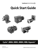
Connect each device as shown in the following figure.
■
Extension cord [1 m]
(optional part: OP-ACDSG1)
●
The length of the cords from the gearmotor is 0.5 m.
●
Please use the extension cord (Option) if you need to extend
the motor signal line.
If it is extended by connecting optional extension cords,
its overall length must be 4.5 m or less
(i.e. up to four extension cords can be used).
*
Shipped with the extension cord
●
Extension cords are not available for the motor power line and having a connector on both ends.
Extend it to 5 m or less using cords with a diameter not smaller
than the specified wire diameter (P17
■
Motor Specification).
Make the motor power line as short as possible in order to
avoid deterioration of motor characteristics.
brake lead wire.
■
Example of connecting to our driver
Note: 1. The maximum extension length for the motor signal line, motor power line, and brake lead wire is 5 m.
If the motor signal line is extended by connecting optional extension cords,
its overall length must be 4.5 m or less (i.e., up to four extension cords can be used).
2. The motor power line is not equipped with a round terminal.
Such terminal must be prepared by the user.
3. The connector is not waterproof specification.
2. Connection method and Installation
2-1 Connection method
Connection to
battery power supply
PC connection cable [1 m] (option)
Connected to PC
I/O cable [0.3 m] (driver accessory)
Connected to control unit Clamp filter (option)
Motor signal line [0.5 m]
Motor power line [0.5 m]
Gear motor
Brake lead wire [0.3m AWG22]
(with brake on)
Connected to brake power supply
8

■
Signal line colors and functions
■
Connector pin configuration
■
Motor power line colors and descriptions
■
Brake lead wire colors and voltage specifications
■
Installation Environment
Ambient Temperature
Item Standard specification Water-resistant specification
IP65
IP40 / IP44
Differs depending on the model
Ingress protection rating
85
%
RH or lower
(no condensation)
Ambient Humidity
A well ventilated place free from corrosive
gas, explosive gas, vapor and/or chemicals.
Not to be exposed to rain and direct
sunlight.
The brake should not be exposed to water,
powders, grease, and/or oil mists.
Models with protection rating of IPX0 should
not be exposed to water directly.
A place free from corrosive gas, explosive
gas and/or vapor.
Not to be exposed to strong rain, wind and
direct sunlight.
Not suitable for use under water, under
environments with exposure to high
pressure water splashes, and under
exposure to cleansing chemicals.
Atmosphere
Wire color
0
℃〜
40
℃
SXA-001T-P0.6
100
%
RH or lower
(no condensation)
1000m or lower1000m or lower
Voltage specification
48V specification
0
℃〜
40
℃
Red U-phase pole signal output (open collector)
White V-phase pole signal output (open collector)
Black W-phase pole signal output (open collector)
Green GND
Socket crimping terminal
Altitude
Description
U-phase
V-phase
W-phase
2-3 Installation
Brown
White
Black
Line color
Red
J.S.T. MFG.
XAP-05V-1
Manufacturer
Plug housing
Line color Function
Yellow Pole sensor power supply (15 V for our driver)
2-2 Motor signal line and power line
Terminal #1 notch
Yellow
Red
White
Black
Green
9

■
Installation Orientation
No restriction on installation orientation. (Since it uses a grease lubrication system)
■
Installation Procedure
[1]
Foot Mount, Flange Mount
[2]
Shaft Mount (torque arm)
The driven shaft must be able to carry the weight of the reducer.
Note) Force other than the rotation reaction force should not be applied to the torque arm.
Tightening torque for installation bolts (reference value)
■
Installing and removing the hollow bore (AFC,F3S)
●
Attaching the Hollow Bore of the Reducer to the Drive Shaft
[1]
[2]
[3]
(Customers need to provide their own spacer, nuts, bolts, keys and shaft bearings.)
[4]
[5]
11 M10 25
{
2.6
}
Mounting Hole Bolt Size Tightening Torque
It is recommended that axial runout for the shaft be 0.05 mm or less at the shaft end. If major wobbling occurs during
operation, it may have a negative effect on the reducer.
Coat the drive shaft surface and bore surface with a lubricant (molybdenum disulfide) suitable to the atmosphere
in which they are used and connect the reducer to the drive shaft.
If the shafts are a tight fit, use a plastic hammer on the end of the hollow bore to insert it. When doing so, be sure
not to hit the casing. If you make a jig like the one in the diagram below, drive shaft insertion will be easier.
When used with uniform loads, a drive shaft tolerance of h7 is recommended. Additionally, when dealing with
impact loads or large radial loads, make sure they fit each other tightly. The tolerance of the interior surface of
hollow bore is designed to be H8.
2-4 Connecting with other equipment
For the length of the turn-stop key for the drive shaft, tolerance range H8 for the bore on the fixed side is recommended.
9 M8 13
{
1.3
}
(
mm
)
(
N
・
m
)
{
(kgf
・
m)
}
Secure the gearmotor with four bolts on a vibration-free and flat machine-processed surface (0.1 mm or less of flatness).
Key
Bore
Tolerance
Range H8 Hollow
Bore
Fixed-End
Bore
Tolerance
Range H8 Spacer
Nut
Bolt
Shaft Bearing
Oil Seal
(Tighten the nut to insert
the output shaft.)
Drive Shaft
10

●
Connecting Reducer to the Drive Shaft
[1] When there are steps on the drive shaft
Fig. : Attachment Using a Spacer and Retaining Ring
(Customers need to provide their own spacer, bolts, and retaining rings.)
Note:Be careful when tightening the bolt, as tightening it too much can distort the shape of the retaining ring.
Fig. : Attachment Using an Endplate
(Customers need to provide their own endplates and bolts.)
Fix the drive shaft between
pillow block bearings
Retaining Ring Bolt
Spacer
Drive Shaft
Fix the drive shaft between
pillow block bearings. Endplate
Bolt
Drive Shaft
11

[2] When there are no steps on the drive shaft
Fig. : Attachment Using a Spacer and Retaining Ring
(Customers need to provide their own spacer, positioning spacers, bolts, and retaining rings.)
●
Recommended Sizes for the Fixing Elments of the Drive Shaft
●
Drive Shaft Length
●
Drive Shaft Key Length
φ30 M8 φ29.5 φ9 5
Make sure the drive shaft reaches both ends of L1. (See
figure at right.) However, look at the dimension leeway for
spacers in the section titled "Removal from the Hollow
Bore."
The length of the key should be at least 1.5 times the width of
the hollow bore. Additionally, the key is inserted in such a
position that at least half its length is in L1. (See figure at
right.)
Recommended Sizes for the Fixing Elements of the Drive Shaft(mm)
Hole
Diameter
Hollow
Bore
Width
Inner
Diameter
Outer
Diameter
Spacer Dimensions
Bolt Size
C-Shaped
Retaining
Ring for
Holes
30
Make sure there is a gap between the outer diameter of the spacer and the bore diameter of the hollow bore. If the fit
is too tight and the outer diameter of the spacer is inaccurate, burning and axial runout of the drive shaft and hollow
bore can result.
The positioning spacer is used to position the reducer. It is not required if you know the length of the drive shaft in
advance. In addition, attaching the positioning spacer allows for smooth removal from the hollow bore. (Refer to "●
Removal from the Hollow Bore" on the next pagefor more on removal from the hollow bore.)
For the attachment of the hollow bore in general use,
we recommend you to refer to the dimensions shown
on the right as a guide line for the strength when
designing.
Fix the drive shaft between
pillow block bearings.
Bolt
Spacer
Retaining Ring
Positioning Spacer
Drive Shaft
Bolt
Spacer
C-Shaped Retaining Ring
12

●
Removal from the Hollow Bore
(Customers needs to provide their own spacers, round plates, bolts and retaining ring keys.)
■
Connecting with Inline Shaft(APG)
●
Against solid shaft
●Against
hollow Bore
(Tightening with ball screw, etc.)
(Tightening with pulley, etc.)
Make sure there is room to spare between the casing and the hollow bore. If you make and
use a jig like the one below, drive shaft removal will be easier.
Commercial
flexible coupling Commercial
tightening device
(The convex spacer prevents rotation)
Key 2
Spacer Cross Section
Key 1 Round Plate Retaining Ring
Spacer (with Tap) Bolt
(The drive shaft will slide out
if this bolt is tightend.)
13

■
Connecting with other equipment
For connecting the reducer to the other equipment, be sure to observe following points.
●
"H7" fit is recommended for the couplings, sprockets, pulleys, gears, etc.
when attaching to the reducer shaft.
1.When directly connected
Connect the reducer to the other equipment precisely, so that the center of the shaft of
both machines will be fully aligned.
2.Attaching Chains, V-Belts, Gears, etc.
・
In any connection, the shaft center of the reducer and the shaft center of
the other equipment must be set parallel to each other.
Also, be sure that the centerline of the sprockets and pulleys are perpendicular to the shaft.
・
In case excessive load is applied to the end of the output shaft, unexpected force could arise,
which may result in crack of the case.
Therefore, insert the sprockets, pulley, gear,etc. to the shoulder of the shaft,
so that the load point could be as close to the reducer as possible.
・
When operating by using belt, be sure not to give too much tension in order to avoid slipping.
Excessive tensioning may result in damage to the bearings of the shaft.
・
When operating by using chain, if the chain is installed loosely, shock load will occur
when the drive shaft starts rotation, and this can result in damage to the reducer and the other equipment.
Therefore, care should be given to the tension of the chain.
<Advantages and disadvantages of flange and torque arm installation>
■
Installing flange
Four bolts should be used.
When the hollow bore is installed directly to the flange
of an application, it can cause motor burn-out or
bearing damage if it is off-center, so be sure to center
it properly.
There is an installation guide, as shown in the diagram
at the right. The dimension tolerance for φA for the
installation guide is h7 in the case of F3S. The
installation bolts are installed as shown in the diagram
at the right.
Advantages Disadvantages
l Can be installed directly on the device.
Torque Arm Installation
l Makes centering with the application easy. l Requires a torque arm.
l Fastening to the application only requires
one detent.
l Requires space for installing a torque
arm.
2-5 Installing Flange/Torque Arm(F3S)
l Saves space.
l
Centering with the application isrequired.
Flange Installation
Installation bolts (4 bolts)
Installation Guide
Application
driven shaft
F3S (Right Angle
Shaft) Application flange
14

■
Detailed diagram of tapped holes for F3S flange mount installation (standard specification)
•
•
•
(Reference value)
Bolt size
Tightening torque N•m {kgf•m}
M10 25 { 2.6}
■Fastening the Reducer and Torque Arm
Install the the torque arm detent to the driven machine side.
Because the torque arm sustains a reactive force from
rotation, consideration needs to be given to impact
loads particularly during startup and braking, Bolts and
plates that are sufficiently strong must be used. It is
best to use an optional torque arm.
To install the torque arm and reducer, fasten
them using spring washers and flat washers with
the installation bolts.
<Bolt Size and Tightening Torque>
B FEDC
15.5 25 φ8.6 40.51/10 to 1/60 0.75 kW φ10.5 M10×P1.5
A
Motor
Power
Reduction Ratio
Frame
No.
30
Detent Ⓐpart
Driven machine side
15

l How to install the Torque Arm Detent Ⓐ part
[1] For normal/reverse rotation operation and unidirectional operation (intermittently)
If mounting has a looseness, impact may be applied to
the torque arm with each startup and defects such
as loosen bolts may occur.
Bolts with sufficient strength shall be used.
(Refer to the right diagram.)
[2] Unidirectional operation (consecutive)
(Refer to ”● Connecting Reducer to the Drive Shaft”.)
Fasten the torque arm detent so there is no looseness or wobble. When doing this, center the
detent hole with that of the application to make sure that no radial load (suspension load) is applied
against the driven shaft and hollow shaft of the reducer. (Refer to the diagram below.)
Note)
If mounting without looseness are not allowed for
some reason, rubber bush or other cushion
materials shall be used between the torque arm
and the bolt as a protective measure.
For unidirectional operation (consecutive) which has no frequent start-up torque applied, the torque arm can be
used without a detent. However, it is still necessary to fasten the driven shaft to the hollow shaft.
In this case, it is necessary to provide sufficient clearance for looseness in both radial and thrust
directions for alignment between the application and detent. (Refer to the diagram below.)
Application Torque arm
Flat washer
Bolt
Spring washer
Nut
Rubber bush or other
cushion materials
Application
Torque Arm
Flat Washer
Bolt
Spring Washer
Nut
Nut
Application Stepped Pin
Torque arm
Leave a gap.
Leave a gap to avoid radial
loads.
Stepped Pin
Torque Arm Hole
Example of Stepped Pin Usage
16

■
Motor Specifications
* Rated current value is a reference value for motor only.(without the gearhead)
About Gearmotor, plase refer the Gearmotor Characteristics(P.18).
■
Electromagnetic Brake Specifications
*
Electromagnetic Brake is meant for holding and should not be used for braking.
IP40/IP44
A place free from corrosive gas, explosive gas and/or
vapor.
Not to be exposed to strong rain, wind and direct sunlight.
Not suitable for use under water, under environments with
exposure to high pressure water splashes, and under
exposure to cleansing chemicals.
IP65
Atmosphere
0.21 A
Motor Power 0.75 kW
Power Draw (at20
℃
)10.0 W
Brake Lead Wire Size 0.3 mm
2
(AWG22)
Be sure to insert a surge protector to protect the driver from surge generated by turning on/off the
electromagnetic brake.
Use the varistor (82V, 1J or higher) included in the package or a diode (100V, 1A or higher).
Altitude
Ambient Humidity
Ambient Storage Humidity
Static Torque (motor shaft) 3.0 N
・
m
Excitation Voltage DC 48V ±10%
Current Draw (at20
℃
)
IP40/IP44
IP65 85%RH or lower (no condensation)
100%RH or lower (no condensation)
1,000m or lower
A well ventilated place free from corrosive gas, explosive
gas, vapor and/or chemicals.
Not to be exposed to rain and direct sunlight.
The brake should not be exposed to water, powders,
grease, and/or oil mists.
Models with protection rating of IPX0 should not be
exposed to water directly.
Motor Power 0.75 kW
2.0G or lower
Voltage DC 48V
Rated Current
Motor Lead Wire Size 2 mm
2
(
AWG14)
Maximum Extended Length 5 m
Ambient Temperature 0
〜
40
℃
3. Specifications and Performance
3-1 Motor and Electromagnetic Brake Specifications
Brake Type Power-Off (Spring Close)
19.5 A
Rating S3
25%
Ambient Storage Temperature -10
〜
60
℃
(no freezing)
IP40/IP44 85%RH or lower (no condensation)
IP65 100%RH or lower (no condensation)
Vibration
Motor Battery Powered Brushless Motor
17

■
Rating
Rating class of this product is Intermittent Rating(S3 25%).
Intermittent Rating(S3) is repeating the cycle which is operation period with constant load
and suspension period without apply voltage,
Duty Factor of this product is 25%.
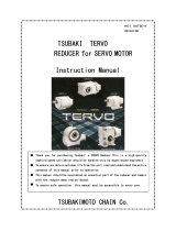
■Gearmotor Characteristics
The coefficient of rotation speed to load and the coefficient of current draw to load for gearmotor units
are shown in these graphs.
These characteristics are gearmotor unit characterisrics.
Customers may refer to these graphs when creating drivers.
* The rotational speed in the graphs below corresponds to the motor shaft.
Use the gear ratio to calculate the output rotational speed.
* In the graphs below, 100% corresponds to output allowable torque in the performance tables.
* Take care to keep the surface temperature of the motor below 90℃.
Load ratio - Current
Duty Factor =
Δt
P
×100
Δt
P
+
Δt
R
When using our driver
Used within the rated speed range (80 to 3000 r/min) at 100% load factor.
3-2 Range of use of Gearmotor
Load ratio - Rotational speed
time t
Load P
Temperature rise θ
Load & Temperature rise
0.75kW 48V Typical Characteristics
Rotational Speed (r/min)
Load Coefficient(%)
Current (A)
18

■
Type and specifications of Hall IC
■
Excitation pattern
・
It rotates in the forward direction as illustrated below.
・
Excitation current flows in the reverse direction through the power lines when rotating in the reverse direction.
Signal transition
Hu
Hv
Hw
U+
U-
V+
V-
W+
W-
ON indicated by the zone
■
Specifications of Motor and Electromagnetic Brake
・
Electromotive force constant and torque constant of a single motor are described below.
・
The resistance values of the electromagnetic brake are described below.
Flow from U to W Flow from V to W
Asahi Kasei Micro devices
15mA
EW-710B
18V
3-3 When making a driver
Flow from W to U Flow from W to V
Manufacturer
0.061
Electromotive Force Constant (V/kr/min)
Torque Constant (Nm/A)
Line Resistance (Ω)at 20ºC 0.12
8.2
Coil Resistance (Ω) at 20ºC
0.75kW
48V
230
Electromagnetic Brake Characteristics
Motor Characteristics
-20
〜
115
℃
Model
Power Supply Voltage
Output Current
Operating Temperature
Flow from V to UFlow from U to V
0.75kW
48V
19

■
Gearmotor
・
All the models that we offer utilize grease for lubrication so replacement and replenishment
of the grease is not required.
The gearmotor is designed for 10,000 hour mark.
・
The service life of the oil seal may differ depending on the environment and usage.
Oil seals may need to replaced before the 10,000 hour mark.
Gearmotor inspection items are described in the table below.
Based on the inspection guideline, determine the best inspection time by judging the usage and environment.
―
―
No increase from
the normal level
―
Remarks
・Make sure that the connections of the
gearmotor case, oil seal, bracket, etc. are
free from leakage.
・Perform cleaning with a cloth,
compressed air, etc.
・ Make sure that the gearmotor-machine
mounting screws are tight enough.
・ Make sure that the gearmotor is firmly
connected to the load.
・ Check for misalignment.
Inspection and
maintenance procedure
・ Check by touch and hearing.
Checking for
grease leakage Every 2 to 3 days
Checking of connection
between gearmotor and
machine
Before the start
of operations
Vibrational and
acoustic check Everyday
Appearance check Whenever
required
Inspection
frequency
Inspection items
4. Maintenance, Service Life, and Inspection
4-1 Maintenance and Service Life
4-2 Periodic Inspection
20
/