Page is loading ...

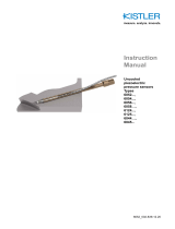
Instruction
manual
Pressure generator
Type 6904A1
6904A_002-716e-12.17


Foreword
6904A_002-716e-12.17 Page 1
Foreword
Thank you for choosing a Kistler quality product
characterized by technical innovation, precision and long
life.
Information in this document is subject to change without
notice. Kistler reserves the right to change or improve its
products and make changes in the content without
obligation to notify any person or organization of such
changes or improvements.
© 2014 … 2017 Kistler Group. All rights reserved. Except
as expressly provided herein, no part of this manual may
be reproduced for any purpose without the express prior
written consent of Kistler Group. Kistler is a registered
trademark of Kistler Holding AG. Kistler Group products
are protected by various intellectual property rights. For
more details visit www.kistler.com
Kistler Group
Eulachstrasse 22
8408 Winterthur
Switzerland
Tel. +41 52 224 11 11
Fax +41 52 224 14 14
info@kistler.com
www.kistler.com

Pressure generator Type 6904A1
Page 2 6904A_002-716e-12.17
Content
1. Foreword ...................................................................................................................................... 3
2. Before you start ........................................................................................................................... 4
2.1 Scope of supply ................................................................................................................... 4
2.2 Safety first ........................................................................................................................... 4
2.3 Golden rules ........................................................................................................................ 4
3. System description ..................................................................................................................... 5
3.1 The selector valve ............................................................................................................... 6
3.2 The spindle .......................................................................................................................... 6
3.3 Sensor mounting ports ........................................................................................................ 7
3.4 Mounting seal configuration ................................................................................................ 7
4. Installation and commissioning ................................................................................................. 8
4.1 Mounting the pressure generator ........................................................................................ 8
4.2 Fitting the lever arms ........................................................................................................... 9
4.3 Check sensor mounting ports ............................................................................................. 9
4.4 Filling the fluid reservoir .................................................................................................... 10
4.5 Purging the system ........................................................................................................... 10
5. Operation .................................................................................................................................... 11
5.1 Mounting sensors .............................................................................................................. 11
5.1.1 Reference sensor ................................................................................................. 11
5.1.2 Unit under test ...................................................................................................... 11
5.2 Priming .............................................................................................................................. 12
5.3 Pressure application .......................................................................................................... 12
6. Appendix .................................................................................................................................... 13
6.1 Dimensions ........................................................................................................................ 13
6.2 Spare parts ........................................................................................................................ 14
6.3 Additional equipment ......................................................................................................... 14
6.4 Calibration fluid.................................................................................................................. 15
Total pages: 15

6904A_002-716e-12.17 Page 3
1. Foreword
Please take the time to thoroughly read this instruction
manual. It will help you with the installation, maintenance,
and use of this product.
To the extent permitted by law Kistler does not accept
any liability if this instruction manual is not followed or
products other than those listed under Accessories are
used.
Kistler offers a wide range of products for use in
measuring technology:
Piezoelectric sensors for measuring force, torque,
strain, pressure, acceleration, shock, vibration and
acoustic-emission
Strain gage sensor systems for measuring force and
torque
Piezoresistive pressure sensors and transmitters
Signal conditioners, indicators and calibrators
Electronic control and monitoring systems as well as
software for specific measurement applications
Data transmission modules (telemetry)
Kistler also develops and produces measuring solutions
for the application fields engines, vehicles, manufac-
turing, plastics and biomechanics sectors.
Our product and application brochures will provide you
with an overview of our product range. Detailed data
sheets are available for almost all products.
If you need additional help beyond what can be found
either on-line or in this manual, please contact Kistler's
extensive support organization.

Pressure generator Type 6904A1
Page 4 6904A_002-716e-12.17
2. Before you start
2.1 Scope of supply
The Type 6904A1 Hydraulic Pressure Generator is
supplied with the following components:
Pressure generator
Lever arms (3)
Bench clamps (2)
Blanking plugs (3)
Spare seal sets (3)
Calibration fluid (500 ml)
Hook wrench
2.2 Safety first
Eye protection must be worn for protection against
possi
ble fluid spray and splashes. Furthermore, a
damaged sensor membrane may result in fluid entering
the sensor body. The subsequent pressure build-up can
cause sensor rapture, which could result in fragments,
e.g. connector parts, being projected through the air.
2.3 Golden rules
High pressure
Always make sure that pressure has been released
before removing any sensors, plugs or adaptors.
Never exceed the specified operating range of the
installed sensors.
Work cleanly
Maintain a clean calibration environment
Clean up any spilt calibration fluid.
Clean the sensor mounting ports every time before
mounting a sensor or adaptor.
Fit the supplied blanking plugs when the Pressure
Generator is not in use.
Torque & Tools
Always use
the correct mounting torques as
specified for each sensor type.
Use specified mounting tools, adapters and seals

System description
6904A_002-716e-12.17 Page 5
3. System description
The Type 6904A1 serves as pressure generator for the
calibration of piezoelectric pressure sensors.
Pressure is generated by a specially developed spindle-
operated plunger pump. The Pressure Generator’s
spindle mechanism delivers ripple-free hydraulic
pressure. This smooth spindle control, together with
minimized trapped air volumes allow for quick and
effective calibration under conditions similar to those
applied in Kistler’s End-of-Line (i.e. factory) calibrations.
Pressure rating
bar
300
Piston diameter
mm
20
Piston Stroke
mm
≈ 75
Displaced volume
ml
≈ 23
Weight
kg
≈ 11
Sensor mounting ports
3x M14x1,25
Calibration fluid
Kistler type 1055 / 1057

Pressure generator Type 6904A1
Page 6 6904A_002-716e-12.17
3.1 The selector valve
The selector valve isolates the cylinder from the fluid
reservoir
Position 0 ("Open")
Fluid can flow freely
between the reservoir and
the pressure cylinder.
The sensor mounting ports
are at atmospheric
pressure.
Use this setting when
priming the pressure
generator.
Position P ("Pressure")
The value is closed, i.e.
the reservoir is isolated
from the pressure cylinder.
Use this valve setting
when applying pressure.
3.2 The spindle
Turning the spindle moves the plunger relative to the
pressure cylinder.
Clockwise
The plunger is driven "into"
the cylinder.
Counterclockwise
The plunger is retracted
"from" the cylinder.
Sensor
Mounting Ports
Spindle
Reservoir
P0Selector
Valve

System description
6904A_002-716e-12.17 Page 7
3.3 Sensor mounting ports
The pressure generator has three sensor mounting ports.
The mounting ports accept shoulder-sealing sensors and
calibration adapters with M14x1,25 mounting threads.
3.4 Mounting seal configuration
Each of the mounting ports is fitted with a seal assembly
as shown below. The pressure generator is also supplied
with three spare seal sets (items 2, 3 and 4):
5 Blanking plug
4 Conical ring
3 Seal ring
2 O-ring

Pressure generator Type 6904A1
Page 8 6904A_002-716e-12.17
4. Installation and commissioning
4.1 Mounting the pressure generator
The pressure generator should be mounted onto a sturdy
workbench or table. It is, furthermore, recommended to
have a non-porous working surface to simplify cleaning in
the event of any spillage.
The base plate can be bolted onto the workbench via four
8mm holes, or clamped using the two provided bench
clamps. The bench clamps are inserted into the base
plate as shown below:
Take note that only the rear section of the clamp should
be in contact with the underside of the workbench. The
workbench should not be in contact with the thread or
front section of the bench clamps.
Correct mounting
Incorrect mounting

Installation and commissioning
6904A_002-716e-12.17 Page 9
4.2 Fitting the lever arms
Mount the three lever arms into the spindle as shown
below. The threaded holes for mounting the lever arms
are drilled at an angle of about 25 °, i.e. hold the lever
arm at a slight incline when assembling.
4.3 Check sensor mounting ports
Ensure that the mounting ports are clean before filling
and using the pressure generator.
Remove the three blanking plugs
If required, use clean compressed air to remove any
possible debris from the port’s seal surface and
internal thread.
Also ensure that each of the mounting ports is fitted
with a seal assembly as shown section 3.4
Re-insert blanking plugs (tighten to 25 N·m).

Pressure generator Type 6904A1
Page 10 6904A_002-716e-12.17
4.4 Filling the fluid reservoir
The reservoir must be filled with the supplied calibration
fluid. (Refer to section 6.3 for more information)
Unscrew the knurled retainer knob and remove the
reservoir lid
Carefully pour some of the supplied calibration fluid
into the reservoir. Do not fill to the brim, the reservoir
should be about "half-full"
Refit the reservoir lid and tighten the retainer knob.
4.5 Purging the system
It is recommended to purge the system prior to
conducting the first calibration. This serves to expel any
air that may be trapped in pressure generator’s cylinder/
plunger mechanism.
Set the selector valve to position 0
Turn the spindle counter clockwise until the plunger is
fully retracted, i.e. it reaches its end stop
Turn the spindle clockwise until it reaches the
opposite end stop.

Operation
6904A_002-716e-12.17 Page 11
25 N.m
KISTLER
UUT
Reference
5. Operation
5.1 Mounting sensors
Ensure that the selector valve is set to
position P before removing any
blanking plugs or sensors.
This will prevent fluid from flowing from
the open mounting port
5.1.1 Reference sensor
It is recommended to mount the reference sensor in one
of the horizontal sensor mounting ports.
Mount the reference sensor using the torque and
tools, as specified in its respective data sheet or
instruction manual
Purge the system, as described in section 4.5
5.1.2 Unit under test
It is recommended to mount the Unit Under Test (UUT) in
the vertical sensor mounting port on the top-side of the
pressure generator.
Mount the UUT as specified, ie. Using its respective
mounting adapter, seals, tools and mounting torque. If
not specified otherwise, calibration adapters should be
mounted with a tightening torque of 25 N·m.
It is generally recommend to:
First mount the calibration adapter onto the pressure
generator
then mount the UUT into the calibration adaptor

Pressure generator Type 6904A1
Page 12 6904A_002-716e-12.17
5.2 Priming
Priming fills the cylinder with calibration fluid prior to
applying pressure.
Set the selector valve to position 0
Turn the spindle counter clockwise until the plunger is
at, at least, mid-stroke, i.e. the indicator rod shows 5
grooves (or less).
5.3 Pressure application
Set the selector valve to position P
Turn the spindle clockwise to increase pressure
Turn the spindle counter clockwise to decrease
pressure
P
t
t
P

Appendix
6904A_002-716e-12.17 Page 13
6. Appendix
6.1 Dimensions

Pressure generator Type 6904A1
Page 14 6904A_002-716e-12.17
6.2 Spare parts
Blanking plug
18009802
O-ring
65007534
Seal ring
65000489
Conical seal ring
65000493
Calibration fluid
1057
6.3 Additional equipment
6935A2
Calibration manifold (6x M14x1.25, 230V)
18006816
6935A4
Calibration manifold (6x M14x1.25, 115V)
18006817
Z18553-701
Connection tube (6904A1 to 6935A)
18009804
1055
Calibration fluid - High temperature
18000007

Appendix
6904A_002-716e-12.17 Page 15
6.4 Calibration fluid
The type 6904A pressure generator has been
designed for use with calibration fluid types
1055/1057. The calibration fluids are based on a
commercial heat transfer fluid called Syltherm1 800.
The heat transfer fluid is filtered and passed through
a distillation process prior to bottling.
Type 1057
The calibration fluid Type 1057 supplied with the
6904A1 is intended for applications at and around
room temperature.
Type 1055
Please use calibration fluid type 1055 for high-
temperature applications, e.g. where the pressure
generator is used in combination with a Type 6935A
high temperature calibration manifold (Type 1055 is
supplied with the Type 6935A)
Do not discard old calibration fluid in
the municipal
trash, into sewers, on the ground or into any body of
water. Disposal must be in compliance with local laws
and regulation
Please refer to the material safety data sheet for
Syltherm 800, which
can be downloaded from the
DOW/Dow Corning websites.
1 Syltherm is a trademark of the Dow Corning
Corporation
/
