Page is loading ...

SOYAL
ACCESS CONTROL SYSTEM
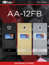
®AR-331H
V171027
CN1 CN2
CN3 CN4 Rubber Pad
AR-721RB
Digital Relay
Board
AR-WG
KEYBOARD-V2
4
6
Best Reading
Area
Arming / Blue LED
Input (Active High)
Yellow LED Input
(Active High)
Left LED Descrption Descrption
Yellow
Blue Power-on/Stand-by
/OK
Error/Alarm
Right LED
Green
Red
Contents
1Product
Security Torx Wrenches
Security Torx: M3x10
Flat Head Cap Philips
Tapping Screw: 4x20
Installation
Connector Table
Peel o screw hole rubbers and frame rubber from rubber pad
Put screw rubbers on the back side of the mounting plate and pull the
cables from the square hole of the mounting plate.
Put a frame rubber on the frame groove of body
Connect the terminal cables to the body and attach the body to the
mounting plate.
Assemble the covers with the Allen key and screws (accessories supplied).
Turn on the power and LED will light up and blink in green.
4Accessories 5Optional
2Terminal Cables 3Tools
Front Panel & Indicator
Wire Application Wire Color Description
Lock Relay 1Blue White (N.O.)DC24V1Amp
2
Purple White
(N.C.)DC24V1Amp
Common-COM-Point
3White (COM)DC24V1Amp
Door Contact 4Orange Negative Trigger Input
Exit Switch 5Purple Negative Trigger Input
Alarm Relay 6Gray Transistor Output Max. 12V/100mA
(Open Collector Active Low)
Power 7Thick Red DC 12V
8Thick Black DC 0V
Cable: CN1
Wire Application Wire Color Description
RS-485 1Thick Green RS-485(B-)
2Thick Blue RS-485(A+)
Cable: CN3
Wire Application Wire Color Description
Anti-Tamper
Switch
1White Tamper Contact 1
2White Tamper Contact 2
Arming 3 Red-White Arming Output (34*000#) / Digital Door
Output (34*128#)
Cable: CN4
Peel
off
screw
rubber
Peel
off frame
rubber
4
5
1
4
2
3
5
6
7
Screws
Rubber
Frame
Rubber
Put on/Take off together
Cable: CN2
Wire Application Wire Color Description
WG Keybard 1White Reserved for BR-WG-KEYBOARD
2White Reserved for BR-WG-KEYBOARD
Wiegand 3Thin Blue Wiegand DAT: 1 Input
4Thin Green Wiegand DAT: 0 Input
Beeper 5Pink Beeper Output 5V/100mA, Low
LED 6Brown Green LED Output 5V/20mA, Max
7Yellow Red LED Output 5V/20mA, Max
While power on the
device,hands o panel
for 10 sec. to make sure
a successful activation.
S/N Since 331HB:1707 , 331HD:1702
AR-721RB
N.C.
N.O.
COM
CTL
12V
GND
PB
WG Reader
POWER
12VDC
PB / Egress
Alarm
12V+
12V+
12V+ 12V+
V-
V-
V- V-
or
Magnet LockElectric BoltAlarm
Electric Strik
eDoor Contact
Lock
Connect to PC
or
Multi-Door
Controller
Push Button
EXIT
WG Door D.O.
Connect to
PC for FW
upgrade
BZ
WG 0
WG 1
R-LED
G-LED
CN2
LA+
LB-
21
Door O.C.(N.O.)
Door O.C.(N.C.)
COM
Door Sensor
PB
Alarm
12V+
V-
CN1CN3
3456
7
AR-331H AR-331K/U
Connect to PC or Multi-Door Controller
Converter
USB-RS485
TCP/IP-RS485
RS232-RS485
Multi-Door
Controller CH1Host CH2
LA+ LB- LA+ LB- LA+ LB-
AR-331H
345 6 78
12
Arming or
TMP Contact 1
TMP Contact 2
G-LED
BZ
WG 0
WG 1
R-LED
CN2
Set 2
Set 1
X
12V+
V-
CN1
CN3
1
2
3
Arming
TMP Contact 1
TMP Contact 2
CN4
34 52
4123
1
765
LA+
13.56MHZ Only
LB-
21
CN4
1
2
1
23
Door.D.O (N.O)
34 128

V171027
CN2
Plug in
21
CN1CN3
34
5
6
7
CN4
1
2
1
2
3456
12
3
AR-331(H)
Access Controller
Touch-panel Metal Housing / Illuminated Touch-panel
External WG keyboard (Only for S/N:1707 and After)
Adding and Deleting Tag
M4/M8
Delete All Tags
Input 123456 (or Master Code) → 29 29
Delete Single Tag
Input 123456 (or Master Code) → 10 SSSSS EEEEE
[e.g.] Delete User Address: 00058
Enter program mode → 10 00058 00058
9
9
Delete a batch of Tags
Input 123456 (or Master Code) → 10 SSSSS EEEEE
[e.g.] Delete User Address: 00101~00245
Enter program mode → 10 00101 00245
9
9
Add a Single Tag or Random tags
Input 123456 (or Master Code) → 19 UUUUU 00001 → Present the tag(s) to Access Controller (single tag or random tags one by one)→ Done
[e.g.] Add 2 random cards to User Addresses No. 100 and No. 101:
Enter program mode → 19 00100 00001 → Present the tags one by one → Done
Input 123456 (or Master Code) → 19 UUUUU QQQQQ → Present the tag (only use the tag with the lowest number) → OK
Add a batch of Sequential tags
[e.g.] Add 20 pcs sequential tags (62312~62331) to User Address NO.101 ~ NO.120:
Enter program mode → 19 00101 00120 → Close Tag into RF Area (only use the tag NO.62312) → OK
M6 ※In this mode, User Address = Card Code
※ If you want to program system on AR-331(H) directly, please order WG keyboard then install it according to the following pattern.
Add Tags
Input 123456 (or Master Code) → 11 SSSSS EEEEE → OK
[e.g.] Add User Address: 00100~01254
Enter program mode → 11 00100 01254 → OK
Delete All Tags
Input 123456 (or Master Code) → 29 29
Delete Tags
Input 123456 (or Master Code) → 10 SSSSS (or )EEEEE → OK
[e.g.] Delete a tag with card code 62362
Enter program mode → 10 62362 62362 → OK
9
Plug AR-331(H) into CN2 connector on the mainboard
Refer to command list and start to operate AR-331(H).
Tag Information
(125kHz) ※ For Mifare tags, the separator between Site Code & Card Code is comma ",".
SITE CODE
CARD CODE
SITE CODE
CARD CODE
7 8
3

V171027
Access Controller
Touch-panel Metal Housing / Illuminated Touch-panel
[e.g.] The anti-pass-back function of User Address 00154 has been enabled. After presenting the card to get in, the user doesn’t present the card to
leave. When s/he tries to present the card to get in again, since the in-in sequence violates the anti-pass-back rule, s/he will be rejected. To solve this
problem, you can reset it as follows. Enter program mode → 26 00154 00154 2 → Reset
Enable/Disable auto-open time zone
Enter program mode → 20 004 [004= enable Auto-Open Time Zone; 000= disable Auto-Open Time Zone]
Enable/Disable auto open door without presenting card
Enter program mode → 24 001 [001= enable Auto-Open Time Zone; 000= disable Auto-Open Time Zone]
[e.g.] Enable the anti-pass-back function of User Address from 00152 to 00684: 26 00152 00684 0
Enable card
Enter program mode → 26 SSSSS EEEEE N
[SSSSS= Starting User Address; EEEEE= Ending User Address; N=0(control)/ 1(Not control)/ 2(reset)]
Enable controller
Enter program mode → 20 DDD [128= Anti-pass-back(0=Disable; 1=Enable)/ 064=Entrance/Exit(0=Exit; 1=Entrance).]
Enter program mode → 20 128 (Please refer to function default value for details.)
[e.g.] Enable Anti-pass-back, and set to Exit door= (128 x 1) + (064 x 0) = 128
N: 2 sets of auto-open zone (N=0=1st set; N=1=2nd set)
HHMMhhmm=Staring time to ending time (e.g. 08301200=08:30 to 12:00)
7123456H= 7 days of a week (Sun/Mon/Tue/Wed/Thu/Fri/Sat) + Holiday (H= 0: disable; 1: enable); Holidays can be set via 701Client software.
Set up auto-open time zone
Enter program mode → 08 N HHMMhhmm 7123456H
[e.g.] To set the second time zone as 9:30 AM to 4:20 PM, Monday, Wednesday and Friday: 08 1 09301620 01010100 → Done
M4/M8: Private PIN
Card or PIN: Enter program mode → 12 UUUUU PPPP [e.g. User Address: 00001 and pass code: 1234, input 12 00001 1234 ]
Card and PIN: Enter program mode → 13 UUUUU PPPP [e.g. User Address: 00001 and pass code: 1234, input 13 00001 1234 ]
M6: Public PIN
Card or PIN: Enter program mode → 15 PPPP [Input 4-digit PIN, default value: 4321; PPPP=0000:
cancel the function of simply inputting PIN to get access
]
Card and PIN: Enter program mode → 17 PPPP [Input 4-digit PIN, default value: 1234; PPPP=0000: access mode will be "Card Only"]
Enter program mode → 00 NNN [Node ID: 001~254; if the access controller is connected to AR-716E, its Node ID will be 001~016.]
Usually, anti-pass-back is commonly applied to parking areas in order to prevent from multi-entry with one card at a time, or to locations that
need entry and exit control.
Door will remain open after the rst ashing card. There are 2 time zones supported when Standalone, and 63 time zones when connected to AR-716E.
Enter program mode → 28 064 [064= Double Door Control]
Controller with a reader to perform the "Double Door Control".
Enter program mode → 04 N [N=4/6/8]
D. Set up the password
E. Double Door Control (M4/M8)
F. Anti-pass-back (M4/M8)
G. Auto-Open Time Zone
B. Change the Node ID of Controller
C.Set up M4/M6/M8
H. Lift control
Enable
Enter program mode → 24 002 [002= enable lift control]
[e.g.] User Address NO. 168, only to the 6th and the 20th oor:
Enter program mode → 21 00168 0 00100000 → 21 00168 2 00001000
Multi oors
Enter program mode → 21 UUUUU S FFFFFFFF
[UUUUU=User Address S: 4 sets of lift control (Input: 0~3) FFFFFFFF: 8 oors setting (F=0: Disable, F=1: Enable)
Single oor
[e.g.] User Address NO. 45, allowed to access the 24th oor: 27 00045 24
Enter program mode → 27 UUUUU FF
UUUU=User Address FF=Floor number (01~32 oor)
Connect with AR-401RO16B to control access oors of users.
Set Floor/ Stop
F
8
16
24
32
0
1
2
3
F
6
14
22
30
F
7
15
23
31
F
5
13
21
29
F
4
12
20
28
F
3
11
19
27
F
2
10
18
26
F
1
9
17
25
Please refer to below oor chart
Master Code modication
Enter program mode → 09 PPPPPPRRRRRR [Input the 6-digit new master code twice.]
[e.g.] Set the Master code to be 876112, input 123456 → 09 876112876112
Enter the program mode
Input 123456 or PPPPPP
[e.g.] The Default Value= 123456, if the Master Code is already changed= 876112, input 876112 → program mode entered
Exit the program mode
Input
Operation process
A. Enter / Exit Program Mode

V171027
Access Controller
Touch-panel Metal Housing / Illuminated Touch-panel
Enable: Enter program mode → Disable: Enter program mode →
Factory Reset by its commands
When the device is Standalone (not networking)
Enter program mode → 20 016 → 24 064 → 26 00000 01023 1→ 28 000 → 29 29
※Note: if the Master Code has been changed, factory reset won't restore the Master Code to 123456.
Enable/Disable Arming status (for M4/M8; default value of arming PWD is: 1234) :
Standby Mode
Enter Program Mode
After door open
The normal procedure to open door → Input 4-digit arming PWD →
Do not open the door
→ Input 4-digit arming PWD → Present a valid card
※ [The normal procedure to open door] can refer to [Access Mode].
I. Setting Up the Arming
Alarm conditions:
1. Arming is enabled
2.Alarm system connected
Application:
1. Door open too long: Door is open longer than door relay time plus door close time.
2. Force open (Opened without a valid user card): Access by force or illegal procedure.
3. Door position abnormal: Arming is enabled and the power is suddenly o then on.
Function Default Value
M4 / M6 / M8
AR-331(H)
20 DDD
Function Selection Value Application
※Default Value
Time Attendance
Auto Relock
Auto Open
Exit by RTE Button
Master Controller of Network
Entrance/Exit
Anti-pass-back
※0: Yes
※0: Disable
※0: Disable
0: Disable
※0: Slave
※0: Exit
※0: Disable
Networking
Networking/Standalone
Networking/Standalone
Networking/Standalone
Networking
Networking
Networking
001
002
004
016
032
064
128
1: No
1: Enable
1: Enable
※1: Enable
1: Mater
1:
Entrance
1: Enable
28 DDD
Function Selection Value Application
※Default Value
Double Door Control
Force Open Alarm Output
※0: Disable
0: Disable
Networking/Standalone
Networking/Standalone
064
128
1: Enable
※1: Enable
※ M6: the user capacity can be 65535 because it only reads 5-digits CARD CODE, while in M4/M8 it reads both SITE CODE and CARD CODE(10 digits).
Select the desired function, Weighted Value =
Selection Index (0 or 1) x Value.
[e.g.] DDD (total weighted value of all functions):
Enable "Auto Open" + "Exit by RTE Button" + "Anti-
pass-back"=1*004 + 1*016 + 1*128=148; As a result
of that, the command will be 20 148 .
65,535
Mode
Networking/
Standalone
Standalone
Networking/
Standalone
Networking/
Standalone
User
Capacity Access Mode
M4
M6
M8
Yes
No
Yes
Yes
No
Yes
Yes
No
Yes
Yes
No
Yes
32
No
32
11
No
11
No
Auto-show
Duty time
Event log
Capacity
120
Holidays
Duress
Function
Time
Zone
Lift
Control
Anti-pass-
back
1.Card only
2.Card and PIN
(4-digit PIN)
+
3.User Address
(5-digit)
+ PIN
(4-digit Private PIN)
+
1.Card only
(using 17* command to set Arming PWD as 0000)
2.Card and PIN
(4-digit public PIN= Arming PWD)
+
3.Card or PIN
(4-digit public PIN= Duress code)
1.Card only
2.Card and PIN
(4-digit Private PIN)
+
3.Card or PIN
(4-digit Private PIN)
3,000 3,000
3,000
3,000
Function Selection Value Application
24 DDD ※Default Value
Auto Open without Presenting in
Auto-open Time Zone
Alarm Output/ Lift
Control
Stop Alarm by pressing RTE Button
or Closing the Door
Doorbell
※0: Disable
※
0: Alarm Output
0: None
※0: Disable
Networking/Standalone
Networking/Standalone
Networking/Standalone
Networking/Standalone
001
002
064
128
1: Enable
1: Lift Control
※ 1: Yes
1: Enable

V171027
Access Controller
Touch-panel Metal Housing / Illuminated Touch-panel
Command List
Mode
M4/M6/M8
M4//M6M8
M4/M8
M4/M8
M4/M8
M4/M8
M4/M6/M8
M4/M6/M8
M4/M6/M8
M4/M6/M8
M4/M6/M8
M4/M8
M4/M6/M8
M4/M6/M8
M4/M6/M8
M6
M4/M8
M4/M8
M4/M8
M4/M8
M4/M6/M8
M4/M8
M4/M6/M8
M4/M6/M8
M4/M8
M4/M6/M8
M4/M8
M6
M4/M8
M4/M6/M8
M4/M6/M8
M4/M8
M4/M8
M4/M6/M8
M4/M6/M8
M4/M6/M8
Function
Enter program mode
Exit program mode
Exit program mode and enter arming mode
Node ID setting (Connected to 716E)
Node ID setting (Connected to the PC directly
without 716E)
Mifare tag / card format (Optional)
Door Relay Time setting
Alarm Relay Time setting
Control mode setting
Arming Delay Time setting
Alarm Delay Time setting
Master card (Administrator) setting
Auto-open time zone setting
Master code setting
Suspend / Delete tag
Add a batch of sequential cards by inputting card
number (M6)
Recover the suspended cards
Set the access mode of the user at the designated
User Address as "Card or PIN"
Set the access mode of the user at the designated
User Address as "Card & PIN"
Arming Pulse Time setting
M4/M8:Duress code setting
M6:Public PIN setting for access mode "Card or PIN"
Card number modication
M4/M8:Arming PWD setting
M6:Public PIN setting for access mode "Card & PIN"
Door Close Time
Add card by presenting(M4/M8)
Reader additional setting
Lift control setting: multi-oor
Add/Delete tag by presenting (M6 only)
AR-401RO16B Lift Relay Activated TM
Controller parameter setting
Controller time clock setting
Anti-pass-back (Enable user)
Lift control setting: single oor
Double Door Control / Force Open Alarm
Delete all tags / Delete all parameter setting
Enable the security trigger signal ( with AR-721RB)
Description
PPPPPP=Master Code, default value=123456
NNN=Node ID of Access Controller (range: 001~016)
NNN=Node ID of Access Controller (range: 001~254)
VVV=Virtual 716E Node ID, nnn=Door number (range:001~254)
N: 0=ISO14443A; 1=ISO14443B; 2=ISO15693;
3=I Code1; 4=I Code2
PS.1. Please select the transmission standard rst.
2. Ensure both reader and card using the same transmission standard.
TTT=Door relay time 000= Output continuously
001~600=1~600 sec.
601~609=0.1~0.9 sec.
TTT=Alarm relay time 000= Output continuously 001~600=1~600 sec.
N=4: M4; N=6: M6; N=8: M8
TTT=the buer time before entering arming mode 001~600=1~600 sec.
TTT=the buer time before the alarm is activated 001~600=1~600 sec.
SSSSS-EEEEE=00000-01023 (00000-03000 for COR-980);
SSSSS=Starting User Address; EEEEE=Ending User Address
N= 0 (1st time zone) / 1 (2nd time zone)
HHMM= Starting time; hhmm= ending time
(i.e.: 08301600=08:30 to 16:00)
7123456H= 7 days of week (Sun/Mon/Tue/Wed/Thu/Fri/Sat)+ Holiday
(H= 0: disable; 1: enable); Holidays can be set by 701Client software.
PPPPPP=6-digit new master code
RRRRRR=Reconrm the new master code
=Suspend =Delete;
SSSSS=Starting User Address, EEEEE=Ending User Address
SSSSS=Starting card number
EEEEE=Ending card number
SSSSS=Starting User Address
EEEEE=Ending User Address
Access mode: Card or PIN; UUUUU=User Address;
PPPP=4-digit private PIN (0001~9999); 0000=Card Only for this user
Access mode: Card & PIN; UUUUU=User Address;
PPPP=4-digit private PIN (0000~9999)
TTT=Arming output time; 000=output continuously 001~250=0.1~2.5 sec.
PPPP=4-digit duress code (0001~9999; default value=4321; 0000=disable
the function of simply inputting PIN to get access in M6)
UUUUU= User Address; SSSSS=5-digit site code; CCCCC=5-digit card code
PPPP=4-digit Arming PWD (0001~9999; default value=1234; 0000= access
mode will become "Card Only" in M6)
TTT=Door Close Time: 001~600=1~600 sec.; default value: 15 sec.
UUUUU=User Address; QQQQQ=Card quantity (00001: for adding a single
card or a batch of random numbering cards)
Please refer to function default value for details.
UUUUU=User Address, S=4 sets of lift control (0~3); FFFFFFFF=8 assigned oor
(F=0: Disable, 1: Enable)
N=0(Delete tag); N=1(Add tag)
NNN=site number, TTT= relay time: 000~600=1~600 sec.
Please refer to function default value for details.
YYMMDDHHmmss: Year/ Month/ Day/ Hour/ Min./ Sec.
SSSSS=Starting User Address; EEEEE=Ending User Address;
N=0: Enable; N=1: Disable; N=2: Reset
UUUUU=User Address; FF=Floor (01~32 oor)
Please refer to function default value for details.
Delete all user data / Delete all parameters
Change the "Arming" (in PIN3 of CN4) to the security trigger signal,
when controller is connected with AR-721RB.
9
Command
PPPPPP
00 NNN
00 NNN VVV nnn
01 N
02 TTT
03 TTT
04 N
05 TTT
06 TTT
07 SSSSS EEEEE
08 N HHMMhhmm 7123456H
09 PPPPPPRRRRRR
10 SSSSS EEEEE (M6)
10 SSSSS EEEEE (M4/M8)
11 SSSSS EEEEE
11 SSSSS EEEEE
12 UUUUU PPPP
13 UUUUU PPPP
14 TTT
15 PPPP
16 UUUUU SSSSSCCCCC
17 PPPP
18 TTT
19 UUUUU QQQQQ
20 DDD
21 UUUUU S FFFFFFFF
22 N
23 NNN TTT
24 DDD
25 YYMMDDHHmmss
26 SSSSS EEEEE N
27 UUUUU FF
28 DDD
29 29 / 29 20
34 128
9

1095 Budapest, Mester utca 34.
Tel.: *218-5542, 215-9771, 215-7550,
216-7017, 216-7018 Fax: 218-5542
Mobil: 30 940-1970, 30 959-0930
www.soyal.hu
1141 Budapest, Fogarasi út 77.
Tel.: *220-7940, 220-7814, 220-7959,
220-8881, 364-3428 Fax: 220-7940
Mobil: 30 531-5454, 30 959-0930
/