Page is loading ...

3. Bore
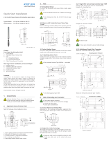
Preparation of the bore for the sensor Type 9239BA
with the mounting nipple Type 9497A1
Erode, mill or grind the bore in the hardened tool steel.
Observe centering and positional alignment.
Quick Start Installation
2.5 mm Cavity Pressure Sensor
Type 9239BA… (–28 pC/N, 2 000 bar, 200°C)
9239BA_012-037e-01.23
Content
Front page: Machining the mold
1. General notes
2. Important areas of sensor bore
3. Bore
4. Cable channeling and connector
Rear page: Sensor installation, service and repair
5. Installing sensor
6. Installing cable and connector
7. Installing identification plate
8. Functional test
9. Service and repair
Foreword
Information in this document is subject to change without
notice. Kistler reserves the right to change or improve its
products and make changes in the content without obligati-
on to notify any person or organization of such changes or
improvements.
To the extent permitted by law Kistler does not accept any
liability if this quick start installation is not followed or pro-
ducts other than those listed under Accessories are used.
© 2023 Kistler Group. All rights reserved. Products of the
Kistler Group are protected by various intellectual property
rights. For more information, visit: www.kistler.com.
1. General notes
• Sensor ø2,5 mm may not be machined
• Front of sensor must be clean and without notches
• Only use recommended installation accessories
• Do not use cable to pull sensor out of bore
1. Contact surface plane, rectangular and clean.
2. Sensor centering 2.55 +0/0.05 mm
3. Coat front side of sensor thinly with grease
2. Important places of the hole
The following points of the hole should be noted:
4.1.1 Single-wire cut and grip connector Type 1839
Machine cable channel and recess for mounting plate.
Example shown: Drilled hole
4. Cable channeling and connector
• Install cables in channels to simplify mold assembly
• Do not route cables next to hot runner cartridge
• Chamfer all sharp edges
• Cover open ducts/slots
4.1 Single-wire cable technology
The single-wire technology uses the tool steel to ensure elec-
trical shielding of the sensor signal. Thus the wiring is routed
through drilled holes.
• Single-wire cable must be completely enclosed in mold
• Single-wire cable may not be routed with power cable
4.1.2 Multichannel single-wire connectors
Recess for 4-channel connector Type 1708B…
Example channel:
• Observe radii
• Cover open ducts with electromagnetic shielding
material
• Clean bore and thread chip-free
Recess for 8-channel connector Type 1710B

Kistler Group
Eulachstraße 22
8408 Winterthur, Switzerland
Tel. +41 52 224 11 11
info@kistler.com www.kistler.com
9239BA_012-037e-01.23 © 2023 Kistler Group
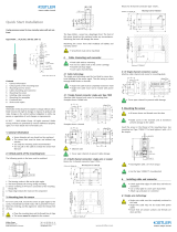
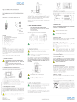
5. Installing sensor
• Ensure all sensor hole and threads are clean
• Radii in the duct and at transitions prevent cable
damage
8. Functional test
On completion of mold assembly, test sensor insulation and
sensitivity.
• Ensure that connector is dry
• Use cleaning spray Type 1003
8.1 Insulation test
Use insulation tester Type 5493 to check sensor insulation.
Resistance >1012 Ω.
9. Service and repair
Piezoelectric pressure sensors are maintenance-free. Insulation
and sensitivity of the installed sensor should, however, be
checked after each molding run.
9.1 Sensor removal
Unscrew the mounting nipple with the socket wrench. Then
screw the extraction tool Type1358A onto the sensor and
carefully remove the sensor from the mounting hole.
• Do not pull on the cable
• Cover the installation hole during cleaning work or
keep it clean
9.2 Single-wire repair
Slightly damaged cables can be repaired using the Repair Kit
Type 1207. If single-wire cables have been severed, solder
ends, slide over Teflon tube and cover with shrink tubing.
.
• Do not overheat sensor and cable when using hot
air blower
9.3 Repairs at Kistler
Factory repairs at Kistler are arranged by the local sales office.
Information: www.kistler.com
9.7 Disposal instructions for electrical and electronic
equipment
Do not discard old electronic instruments in
municipal trash. For disposal at end of life,
please return this product to an authorized
local electronic waste disposal service or
contact the nearest Kistler Instrument sales
office for return instructions.
5.1 Sensor installation with mounting nipple Type
9497A1 and socket wrench Type 1300A169
Connect the connection cable to the sensor and pre-assemble
it with the mounting nipple. The nut of the mounting nipple
must point upwards (see picture).
Coat the face of the sensor (ø 2.5 mm) with grease.
Connect the sensor to a charge amplifier (e.g. Preload Tester
Type 5991) and carefully preload it using the socket wrench Type
1300A169 until it delivers the specified charge of -10.200 pC
(corresponds to 360 N).
6. Installing cable and connector
• Check again that there are no sharp edges in the
cable hole and duct
• Provide open channels with cover plate
• Fasten cover and cover plug
6.1 Single-wire technology
• Single-wire cable must be completely enclosed in
the mold
• Single-wire cable may not be routed with power
cables
• Ensure that all contact surfaces and threads are clean
and dry
6.1.1 Cut & grip connection
Cut the single-wire cable to length and do not strip the
insulation. Loosen the knurled connector by hand without
removing the rear section.
6.1.2 Installing single-wire connector
Install connector and mounting plate in recess. Attach cap
using one of the screws. Place cap on open connector.
Installation of connector Type 1839 and mounting plate
Installation of multichannel connector
Example: Type 1708B0
Mounting bore with sensor
Montagenippel Typ 9497A1
7. Installing identification plate
Rivet plate to side of mold or fit with four M2,5 screws.
/
