Soyal AR-723H Proximity Access Controller User manual

Type
User manual

Soyal AR-723H Proximity Access Controller provides advanced features for access control and security. Its slim design allows for easy installation, and it offers versatile connectivity options with two terminal cables. The controller supports multiple access modes, including card only, card and PIN, and card or user address with individual PIN. It also enables various functions such as auto-open, door open button input, and lift control. With its built-in security digital opening signal and watchdog to prevent hanging up, the AR-723H ensures reliable operation.

Soyal AR-723H Proximity Access Controller provides advanced features for access control and security. Its slim design allows for easy installation, and it offers versatile connectivity options with two terminal cables. The controller supports multiple access modes, including card only, card and PIN, and card or user address with individual PIN. It also enables various functions such as auto-open, door open button input, and lift control. With its built-in security digital opening signal and watchdog to prevent hanging up, the AR-723H ensures reliable operation.

SOYAL®AR-723 (H) V200620
Access Controller
AR-WG-KEYBOARD AR-721-RBAR-821-RB
CN1
CN3
LED
BZ
12345678
AR-821RB
AR-723 (H)
N.C.
N.C.
N.O.
COM
CTL
AR-821RB
N.O.
AR-721RB
N.O.
N.C.
N.C.
N.O.
COM
EXIT
CTL
DECODER
N.C.
N.O.
COM
CTL
PB
EXIT
CN1 CN3
V+
V+
V-
LED
BZ CN3
AR AR
-7 -7
23 (H) 23 (H)
1
1
1
2
2
2
3
3
3
4
4
4
5
5
5
6
6
6
7
7
7
8
8
8
V-(GND)
ALM
PB
SEN
A+
B-
V+
Door
V-(GND)
ALM
PB
SEN
A+
B-
V+
Door
V-(GND)
ALM
PB
SEN
A+
B-
V+
Door
WG 0
WG 1
7
6
5
4
3
2
1
CN3
V -
WG0
WG1
V+
AR-723 (H)
V-
V+
Networking: 8 PIN (RS-485)
FCC ID: 2ACLEAR-723-H
Diagram
Electric Strike Electric Bolt
Request To Exit Request To Exit
Alarm
Door Contact
POWER
12VDC
DC
POWER
DC
POWER
DC
POWER
POWER
12VDC
Connect to Electric Strike Strengthen security with AR-721RB
Connect to Reader or KeyboardConnect to Door Contact and Alarm
Connector Table
CN3 WG-READER or KEYBOARD Socket
CN1
Content & Feature
1Product 4Feature
3Optional
2Terminal Cables
Slim design makes installation easy
MASTER CARD for adding / deleting tags
Set up parameters and user tags by external WG Keyboard
Built-in security digital opening signal
Built-in Watchdog to prevent from hanging up
Application Wire Color Description
Power 1 Black DC 0V (GND)
2 Red DC 9-24V
Alarm Relay 3 Gray Open collector output
R.T.E 4 Purple Negative Trigger Input
Door Contact 5
Orange
Negative Trigger Input
Lock Relay 6 White Open collector output/ Security Trigger Signal
RS-485 7 Green RS-485 B-
8 Blue RS-485 A+
Application Wire Color Description
1
2
3
WG 4 Blue WG DATA 1
5 Green WG DATA 0
Power 6 Red DC 9-24V
7 Black DC 0V (GND)
or
Please unload the cover before plug in AR-WGKEYBOARD.
Diode
Master Card x2
or
Magnetic Lock
V+
WG Reade
WG Key
r
board
or
Re
Black
d
Green
Blue
V200620
323DMaster
2
1
AR-723 (H)
321CM
A+
B- 7
8
RS485
AR-723 (H)
Access Controller
About Master Card
Enter the program mode
Input 123456 or PPPPPP
[e.g.] The Default Value= 123456, if already changed the Master Code= 876112, input 876112program mode accessed
Exit the program mode
Input
Operation process
M4/M8: Individual pass code
Card or PIN: Access programming mode12 UUUUU PPPP [e.g. User address: 00001 and pass code: 1234, input 12 00001 1234 ]
Card and PIN: Access programming mode13 UUUUU PPPP [e.g. User address: 00001 and pass code: 1234, input 13 00001 1234 ]
M6: Public pass word
Card or PIN: Access programming mode15 PPPP [Input 4-digit pass code, default value: 4321]
Card and PIN: Access programming mode17 PPPP [Input 4-digit pass code, default value: 1234; PPPP=0000: change into Card Only]
B. Set up the password [Only for connect to external K-series reader]
Master Code modication
Access programming mode09 PPPPPPRRRRRR [Input the 6-digit new master code twice.]
[e.g.] Set the Master code to be 876112, input 12345609 876112876112
A. Enter/ Exit Program Mode
Adding Tag
Present Master Card
Deleting All Tags
Present Master Card
P.S. Once MASTER CARD is presented after one
warning beep, all card data will be cleared.
After 3 short beeps
[Access programming mode]
After 3 short beeps
[Access programming mode]
Present the new card or cards
one by one till nished the adding.
1 long warning beep after 2sec.
Present Master Card
[Exit programming mode]
5 short beeps after 5sec: cards cleared
1. 1.
2. 2.
3. 3.
4.
4.
MASTER CARD Setting for Stand-Alone
Use the MASTER CARD software
Input the MASTER CARD number, and press [Write].
Cut o and then transmit the power, the master card number will be activated.
Present the card, and the reader will ash green light 3 times and sound 3 beeps. Then the card becomes MASTER CARD and accesses programming
mode.If MASTER CARD is presented again, it will exit programming mode.
Converter USB
C. Lift control
Enable
Access programming mode24 002 [002= enable lift control]
Connect with AR-401RO16B to control oors which the user will be able to access.
[e.g.] User address NO. 168, only to the 6th and the 20th oor:
Access programming mode21 00168 0 00100000 21 00168 2 00001000
Multi oors
Access programming mode21 UUUUU S FFFFFFFF
[UUUUU=User address S: 4 sets of lift control (Input: 0~3) FFFFFFFF: 8 oors setting (F=0=Disable, F=1=Enable)
Single oor
[e.g.] User address NO. 45, allow to access the 24th oor: 27 00045 24
Access programming mode27 UUUUU FF
UUUU=User Address FF=Floor number (01~32 oor)
Set Floor/ Stop
F
8
16
24
32
0
1
2
3
F
6
14
22
30
F
7
15
23
31
F
5
13
21
29
F
4
12
20
28
F
3
11
19
27
F
2
10
18
26
F
1
9
17
25
SOYAL®AR-723 (H) V200620
Access Controller
Enable: Access programming mode Disable: Access programming mode
Factory Reset by its commands
When the device is stand-alone (not networking)
Access programming mode20 01624 06426 00000 01023 128 00029 29
Note: After the Master Code is changed, factory reset doesn’t restore the Master Code back to 123456.
Enable/Disable Arming status (for M4/M8; Factory default armingcode is: 1234) :
Standby Mode
Enter Program Mode
After door open
The normal procedure to open doorInput 4 digit arming code
Do not open the door
Input 4 digit arming codePresent valid card
[The normal procedure to open door] can refer to [Access Mode].
D. Setting Up the Arming [Only for connect to external K-series reader]
Alarm conditions:
1. Arming is enabled
2.Alarm system connected
Application:
1. Door open too long: Door is open longer than door relay time plus door close time.
2. Force open (Opened without a valid user card): Access by force or illegal procedure.
3. Door position abnormal: Arming is enabled and the power is suddenly o then on.
Function Default Value
Mode4 / Mode6 / Mode8
Mode 6, the number of users up to 65535, since it reads CARD CODE(5 digits) only, unlike that Mode4/Mode8 read SITE CODE and CARD CODE(10 digits).
If Access Mode setting to use the PIN, it need to external the K-series Readers.
Selection= 0(none value)/ 1(1 x each value)
[e.g.] DDD value of Enable “Auto Open” + ”Exit by Push Button + ”Anti-pass-back”
=(0x1)+(0x2)+(1X4)+(1x16)+(0x32)+(0x64)+(1x128)=148 ; As a result of that, the command will be 20 148 .
20 DDD Default Value
Function Selection Value Application
Attendance 0: Yes 1: No 001 Networking
Auto Re-lock 0: Disable 1: Enable 002 Networking/Stand-Alone
Auto Open 0: Disable 1: Enable 004 Networking/Stand-Alone
Door open button input 0: Disable 1: Enable 016 Networking/Stand-Alone
Master Controller of Network 0: Slave 1: Mater 032 Networking
24 DDD Default Value
Function Selection Value Application
Auto-open door without cards at auto open zone 0: Disable 1: Enable 001 Networking/Stand-Alone
Alarm Output/ Lift Control 0: Alarm Output 1: Lift Control 002 Networking/Stand-Alone
Stop Alarm by door close or by push button 0: None
1: Yes 064 Networking/Stand-Alone
28 DDD Default Value
Function Selection Value Application
Dual Door Control 0: Disable 1: Enable 064 Networking/Stand-Alone
Force Open Alarm Output 0: Disable 1: Enable 128 Networking/Stand-Alone
Mode Networking/
Stand-Alone
User
Capacity Access Mode Auto-show
Duty time
Event log
Capacity
120
Holidays
Anti
force
Time
Zone
Lift
Control
Anti-pass-
back
M4
Networking/
Stand-Alone
1,024
1.Card only
2.Card and PIN
(4-digit PIN)
+
3.Card or User address
(5-digit)
+ Individual PIN
(4-digit
individual PIN)
+
Yes 1,200 Yes Yes No 32 Yes
M6 Stand-Alone 65,535
1.Card only
2.Card and PIN
(4-digit public PIN= Arming PWD)
+
3.Card or PIN
(4-digit public PIN= Duress code)
No No No No No No No
M8
Networking/
Stand-Alone
1,024
1.Card only
2.Card and PIN
(4-digit individual PIN)
+
3.Card or PIN
(4-digit individual PIN)
Yes 1,200 Yes Yes No 32 Yes
V200620
AR-723 (H)
Access Controller
Command List
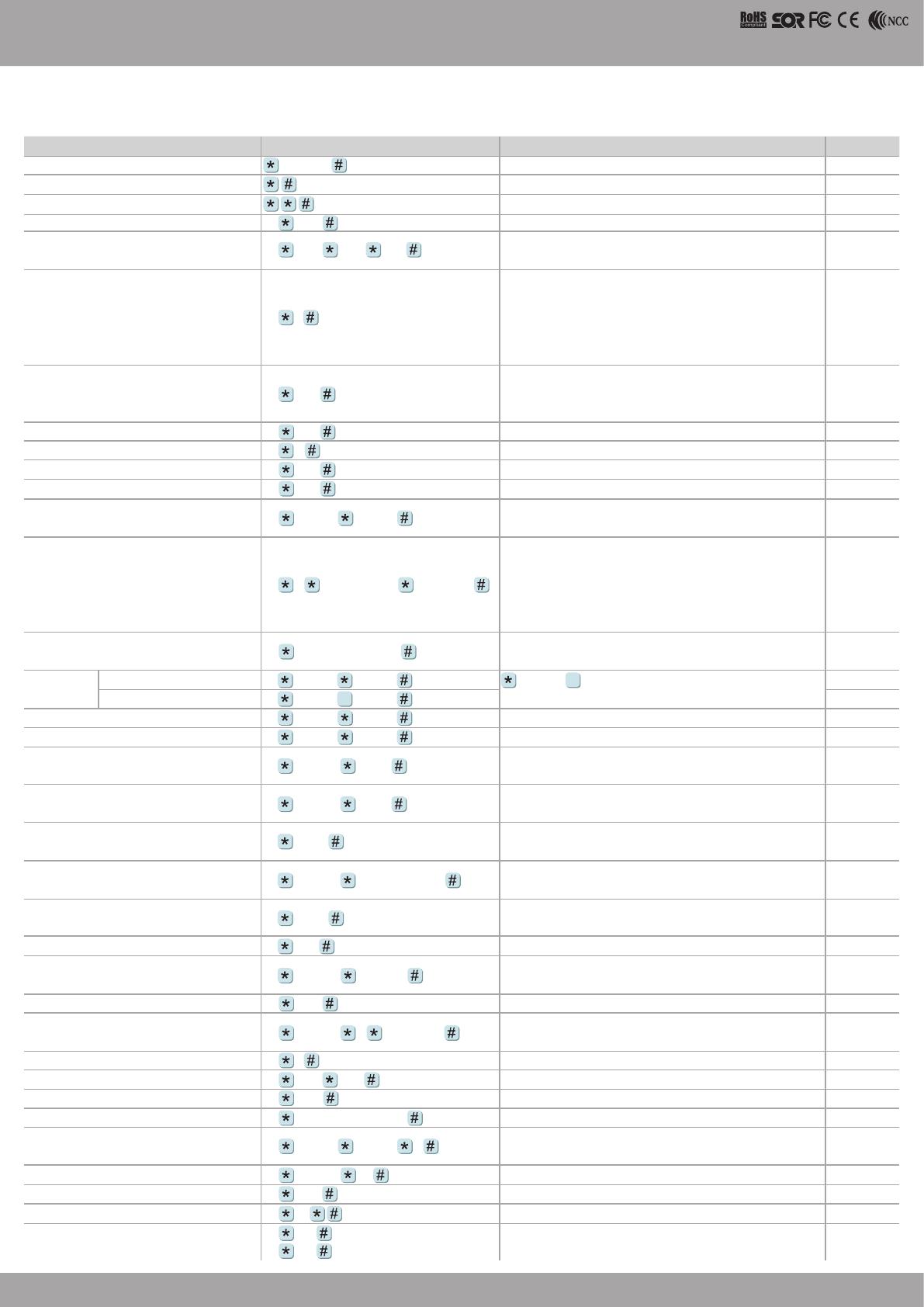
Function Command Description Mode
Entering programming mode PPPPPP PPPPPP=Master Code, default value=123456 M4/M6/M8
Exiting programming mode M4/M6/M8
Exiting programming mode and enabling arming status M4/M8
Node ID setting (Connecting to 716E 00 NNN NNN=Node ID, range: 001~254 M4/M8
Node ID setting (Connecting to PC directly without
via 716E) 00 NNN VVV nnn NNN=Node ID of Access Controller, VVV=Virtual 716E Node ID,
nnn=Door number; range:001~254 M4/M8
Mifare tag / card format (Optional) 01 N
N: 0=ISO14443A; 1=ISO14443B; 2=ISO15693;
3=I Code1; 4=I Code2
PS.1. Please select the compliance,rst.
2. Make sure reader and card using the same compliance.
M4/M8
Door relay time setting 02 TTT
TTT=Door relay time 000= Output constantly
001~600=1~600 sec.
601~609=0.1~0.9 sec.
M4/M6/M8
Alarm relay time setting 03 TTT TTT=Alarm relay time 001~600=1~600 sec. M4/M6/M8
Control mode setting 04 N N=Mode 4=Mode4; 6=Mode6; 8=Mode8 M4/M6/M8
Arming delay time setting 05 TTT TTT=Alarm relay time 001~600=1~600 sec. M4/M6/M8
Alarm delay time setting 06 TTT TTT=Alarm delay time 001~600=1~600 sec. M4/M6/M8
Master card setting 07 SSSSS EEEEE SSSSS-EEEEE=00000-01023 (00000-03000 for AR-725H);
SSSSS=Starting user address; EEEEE=Ending user address M4/M8
Auto-open time zone setting 08 N HHMMhhmm 6543217H
N= 0(1st time zone) / 1(2nd time zone)
HHMM= Starting time; hhmm= ending time
(i.e.: 08301200=08:30 to 12:00)
6543217H= 7 days of week (Sat/Fri/Thu/Wed/Tue/Mon/Sun)+ Holiday
(F= 0: disable; 1: enable); Holidays establish by the software.
M4/M6/M8
Master code setting 09 PPPPPPRRRRRR PPPPPP=New master code
RRRRRR=Repeat the new master code M4/M6/M8
Setting
Suspend tag(M6) 10 SSSSS EEEEE =Suspend =Delete;
SSSSS=Starting user address, EEEEE=Ending user address
M4/M6/M8
Delete tag(M4) 10 SSSSS EEEEE M6
Set a sequence of cards as "read and access" 11 SSSSS EEEEE SSSSS=Starting card number; EEEEE=Ending card number M4/M8
Active the suspended cards 11 SSSSS EEEEE SSSSS=Starting user address; EEEEE=Ending user address M4/M8
Set the cards as Card mode OR PIN mode by user
address 12 UUUUU PPPP Access mode: Card or PIN; UUUUU=user address;
PPPP=4-digit pass code 0001~9999 M4/M8
Set the cards as Card AND PIN mode by user
address 13 UUUUU PPPP Access mode: Card and PIN; UUUUU=user address;
PPPP=4-digit pass code 0001~9999 M4/M6/M8
M4: Duress code setting
M6: Public PIN setting (Card or PIN) 15 PPPP PPPP=4-digit pass code (default value=4321)
P.S. Duress code will be unavailable and become a public PIN at access mode “Card or PIN” of M6 M4/M8
Card number modication 16 UUUUU SSSSSCCCCC UUUUU= User address; SSSSS=5-digit site code;
CCCCC=5-digit card code M4/M6/M8
M4: Arming pass code setting
M6: Public PIN setting (Card and PIN) 17 PPPP PPPP=4-digit pass code ( default value=1234; disable Arming PWD=0000)
P.S. Arming PWD code will be unavailable and become a public PIN at access mode “Card PIN” and of M6 M4/M6/M8
Door open waiting time 18 TTT TTT=Door open waiting time: 001~600=1~600 sec.; default value: 15 sec. M4/M8
Set the card by induction (M4) 19 UUUUU QQQQQ UUUUU=User address;
QQQQQ=Card quantity(00001=Continuously inducting) M4/M6/M8
Reader additional setting 20 DDD Please refer to function default value for details. M4/M6/M8
Lift control setting: multi-doors 21 UUUUU S FFFFFFFF UUUUU=User address, S=4 sets of lift control(0~3); FFFFFFFF=8 assigned oor
(F=0: Disable, 1: Enable) M4/M8
Add/Delete tag by induction (M6 only) 22 N N=0(Delete tag); N=1(Add tag) M6
AR-401ROsite number dip switch 23 NNN TTT NNN=site number, TTT= relay time: 000~600=1~600 sec. M4/M8
Controller parameter setting 24 DDD Please refer to function default value for details. M4/M6/M8
Controller time clock setting 25 YYMMDDHHmmss YYMMDDHHmmss: Year/ Month/ Day/ Hour/ Min./ Sec. M4/M6/M8
Anti-pass-back (Enable user) 26 SSSSS EEEEE N SSSSS=Starting user address; EEEEE=Ending user address;
N=0/Enable; N=1/Disable; N=2/Initial M4/M8
Single oor setting 27 UUUUU FF UUUUU=User Address; FF=Floor (01~32 oor) M4/M8
Dual door control/ Active or inactive arming for force open 28 DDD Please refer to function default value for details. M4/M6/M8
Delete all tags 29 29 M4/M6/M8
Enable the security trigger signal ( with AR-721RB) 34 064 (Enable)
34 000 (Disable)
Change the "Door Lock" become the security trigger signal when
connecting with AR-721RB. M4/M6/M8
9
9
SOYAL®AR-723 (H) V200620
Access Controller
FCC ID: 2ACLEAR-723H
This device complies with part 15 of the FCC Rules. Operation is subject to the following two
conditions: (1) this device may not cause harmful interference, and (2) this device must accept any
interference received, including interference that may cause undesired operation.
Any changes or modications not expressly approved by the party responsible for compliance could
void the user's authority to operate the equipment.
NOTE: This equipment has been tested and found to comply with the limits for a Class B digital
device, pursuant to Part 15 of the FCC Rules. These limits are designed to provide reasonable
protection against harmful interference in a residential installation. This equipment generates,
uses and can radiate radio frequency energy and, if not installed and used in accordance with
the instructions, may cause harmful interference to radio communications. However, there is no
guarantee that interference will not occur in a particular installation.
If this equipment does cause harmful interference to radio or television reception,
which can be determined by turning the equipment o and on, the user is encouraged to try to
correct the interference by one or more of the following measures:
-- Reorient or relocate the receiving antenna.
-- Increase the separation between the equipment and receiver.
-- Connect the equipment into an outlet on a circuit dierent
from that to which the receiver is connected.
-- Consult the dealer or an experienced radio/TV technician for help. The device has been
evaluated to meet general RF exposure statement.
The device can be used in portable exposure condition without restriction
Warning: Changes or modications to this unit not expressly approved by the part responsible for
compliance could void the user’s authority to operate the equipment
This device complies with Industry Canada licence-exempt RSS standard(s).
Operation is subject to the following two conditions:
(1) This device may not cause interference, and
(2) This device must accept any interference,
including interference that may cause undesired operation of the device.
  • Page 1 1
  • Page 2 2
  • Page 3 3
  • Page 4 4
  • Page 5 5

Soyal AR-723H Proximity Access Controller User manual

Type
User manual

Soyal AR-723H Proximity Access Controller provides advanced features for access control and security. Its slim design allows for easy installation, and it offers versatile connectivity options with two terminal cables. The controller supports multiple access modes, including card only, card and PIN, and card or user address with individual PIN. It also enables various functions such as auto-open, door open button input, and lift control. With its built-in security digital opening signal and watchdog to prevent hanging up, the AR-723H ensures reliable operation.

Ask a question and I''ll find the answer in the document

Finding information in a document is now easier with AI