Page is loading ...

9540-N SMART DIMMER, SINGLE-POLE/MULTI-LOCATION- 300W DIMMABLE LED/CFL- 600W INC/DIMMABLE ELV/HALOGEN/DIMMABLE
FLR 600VA MLV - 120V/AC, 60 Hz REQUIRES NEUTRAL CONNECTION IN WALLBOX
SPECIFICATIONS
• For dimmable LED/CFL, Incandescent (INC), Magnetic Low Voltage (MLV), Electronic Low Voltage (ELV), Halogen or dimmable
fl uorescent light fi xtures.
• Ability to set Min/Max dimmer level for maximum compatibility with different loads.
• Rapid start feature which allows the light to come on instantly in the case of LED/CFL loads and the ability to disable that feature.
• One Master Dimmer works with up to fi ve (5) Accessory Dimmers.
• NOTE - A Neutral Connection is required in the wallbox where the Master Dimmer will be installed.
• Compatible with Mark 10® Powerline, AmbiStar® and Tu-wire® dimmable ballasts.
OPERATION INSTRUCTIONS
• Press ON/OFF button once to turn lights ON at the previously selected level.
• Press again to turn lights OFF.
• When lights are OFF, press and hold for 2 seconds for full brightness.
• To activate delay off feature, when lights are ON, press and hold for 2 seconds until the green LED fl ashes then release. After 10
seconds, the lights will begin fading to OFF. This allows you time to exit the room before the lights turn off.
• Amber LED indicates that the dimmer is turned on.
DIMMING LEVEL ADJUSTMENT
For maximum compatibility with different loads types, 9540-N allows the user to set the minimum level. Also to save on power consumption 9540-N allows the user to set the maximum level.
1. After installing the dimmer and restoring power:
2. Press on/off button to turn on the light.
3. Press and hold on/off button for fi ve seconds until the green dimmer LEDs begin to cycle rapidly (NOTICE- after two seconds green dimmer LEDs will start to fl ash indicating activation of the delay off feature.
Continue holding the ON/OFF button for three additional seconds until the green dimmer LEDs begin to cycle rapidly.)
4. Release the button. Dimmer will set the light to the previously saved minimum level (that may cause the light to fl icker or turn off). During initial setup, the light will set to the factory minimum default.
5. Press either the dim or bright buttons to change the minimum level until the light output is acceptable.
6. Press ON/OFF button. Green dimmer LEDs will start to cycle rapidly again and the dimmer light will go to previously saved maximum level.
7. Press either the dim or bright buttons to change the maximum level until the light output is acceptable.
8. Press ON/OFF button, LED will fl ash indicating completion of programming
• NOTE – To restore the default min/max, repeat the steps above and adjust light levels to full min/max settings by pressing dim/bright buttons until the light output no longer changes.
• NOTE - User could ignore setting max or min by pressing on/off button without changing the dimmer level.
Rapid start feature
This feature ensures that LED/CFL lights turn on when the dimmer preset level is low. With this setting enabled, the lights may momentarily be brighter than the preset level (less than one second) and then dim
down to the preset level.
Depending on the type of light used, this feature may not be needed.
To enable/disable the feature, turn lights on. Press and hold the on/off button for 10 seconds until the green dimmer LEDs fl ash for the third time, then release the button.
INSTALLATION INSTRUCTIONS
WARNING:
• Turn OFF circuit breaker or remove fuse(s) and verify that power is off before wiring.
• Never wire any electrical device with power turned on. Wiring the dimmer with power on may cause permanent damage to the dimmer and void the warranty.
• If you are unsure about any part of these instructions, or if the wiring does not match the descriptions given, you should call a qualifi ed electrician.
CAUTION:
1. Do not exceed maximum rating of the dimmer as indicated in Table 1.
2. Must be installed and used in accordance with electrical codes.
3. If a bare copper or green ground connection is not available in the wallbox, contact a licensed electrician for installation. Do not install without proper ground connections.
4. To avoid overheating and possible damage to other equipment, do not use to control receptacles, motor-driven appliances, transformer supplied appliances, etc.
5. Use only #14 or #12 copper wire rated for at least 75º C with these devices. Do not use with aluminum wire.
6. Be sure to read and follow all instructions associated with the specifi c lamp that you are using with the dimmer.
7. The Smart Dimmer will not work or will become damaged if wired incorrectly, and the warranty will be voided. Refer to wiring instructions in this document.
Tools needed for Installation:
• Screwdriver (Slotted/Phillips) • Pliers • Cutters
SINGLE OR MULTI-LOCATION APPLICATION
Determine which type of installation it is.
• Single Location – Controlled from one location.
• Multi-Location – Controlled from more than one location. One location is the Master Dimmer and the other location(s) are the
Accessory Dimmers.
• Turn off the power and remove wallplate.
• NOTE – The Smart Dimmer is not compatible with standard
3-way switches.
• NOTE – A neutral wire must be available in the wallbox.
SINGLE LOCATION INSTALLATION
Disconnect the existing switch, remove it and connect as per
FIGURE 1 using the wire nuts provided:
• Connect the Dimmer black wire to the hot wire (black) in the
wallbox.
• Connect the Dimmer red wire to the wire that goes to the light
fi xture (black).
• Connect the Dimmer white wire and yellow wire to the neutral
wire (white) in the wallbox.
• Connect the Dimmer green wire to the ground wire in the
wallbox.
• Install the Dimmer loosely using the mounting screws provided.
• Apply power temporarily and verify that one of the green dimmer
LED’s is on. Push the ON/OFF button to verify the lights turn ON and
OFF. If the lights do not work, then turn off the power and swap the
dimmer red and black wires.
• Apply power again and verify that the dimmer works by pushing the
ON/OFF button to verify the lights turn ON and OFF.
• Turn power OFF. Refer to COMPLETING THE INSTALLATION.
IMPORTANT – HOW TO IDENTIFY COMMON WIRES
For Two and Three location installations you must fi rst identify the Common
Wires.
TWO LOCATION:
On a 3-way switch the common wire is identifi ed by a marking on the switch
indicating COM, or the screw color is Black, and is different than the other two
screws. Tag this wire before disconnecting the wires from the switch.
THREE LOCATION:
• Two of the existing switches will be 3-Way. The 3-way switches will be located
at each end of the circuit with a 4-way switch in between. Tag the two 3-way
switches as in the Two Location section.
• The 4-way switch has four insulated wires
connected to four terminal screws. Two wires should be Red and two should
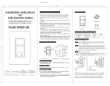
Press to DIM
Light level may be adjusted
with lights ON or OFF
Press to BRIGHTEN
Disconnect Switch Pull out to change bulbs
(Master Dimmer only)
LED ON/OFF indicator
(amber)
Light level indicators
(green)
ON/OFF Button
GREEN
RED
OUTPUT
(WHITE) WHITE
(WHITE)
YELLOW
NEUTRAL
HOT
(BLACK) BLACK
(BLACK)
GROUND
FIGURE 1: SINGLE LOCATION WIRING DIAGRAM
LED/CFL, INC,
ELV/MLV, FLR
OR HALOGEN
HOT
TAG
TAG
BLACK
GREEN
RED Travellers
(RED) (BLACK)
(WHITE)(WHITE)
WHITE
3-WAY LOCATION 3-WAY LOCATION
NEUTRAL
YELLOW (BLACK)
BLUE
BLUE
MASTER
ACCESSORY
GROUND
GREEN
GROUND
FIGURE 2: TWO LOCATION INSTALLATION WIRING DIAGRAM
(BLACK)
(WHITE)
LED/CFL, INC,
ELV/MLV, FLR
OR HALOGEN
TABLE 1
Load Type One Gang Two Gang Three Gang
INC/ELV/FLR/Halogen
600W 550W 500W
MLV
600VA 550VA 500VA
CFL/LED 300W 300W 300W
ENGLISH

be Black.
TWO LOCATION INSTALLATION:
• For the existing wiring identify the common wires
for both 3-way switches, and tag these wires by
following the instructions “How to Identify
Common Wires”. Refer to FIGURE 2.
• The Master Dimmer must be installed in the 3-way
location that is connected to Power.
• If you are unsure how to determine this, consult a
qualifi ed electrician.
• Connect the Master Dimmer as follows using the
wire nuts provided:
1. Connect the Dimmer Black wire to the tagged Hot
wire (Black).
2. Connect the Dimmer White wire to the two white
wires (Neutral).
3. Connect the Dimmer Red wire to the Red Wire
(Traveler).
4. Connect the Dimmer Yellow wire to other Black
Wire (Traveler).
5. Connect the Dimmer Green wire to the Ground
wire in the wallbox.
• Connect the Accessory Dimmer as follows using the wire nuts provided:
1. Connect the Black wire from the light fi xture to the Red Traveler wire.
2. Connect either of the Dimmer blue wires to the Black Traveler wire.
3. Connect the two white wires to the other Dimmer Blue wire.
4. Connect the Dimmer Green wire to the Ground wire in the wallbox.
• Go to COMPLETING THE INSTALLATION.
THREE LOCATION INSTALLATION:
• For the existing wiring identify the common wires for both 3-way switches, and tag these wires by following the instructions provided above. Refer to FIGURE 3.
• The Master Switch must be installed in the 3-Way location that is connected to Power.
• If you are unsure how to determine this, consult a qualifi ed electrician.
• Connect the Master Dimmer as follows in the location of the 3-way switch that was connected to Power, using the wire nuts provided:
1. Connect the Dimmer Black wire to the tagged Hot wire (Black).
2. Connect the Dimmer White wire to the two white wires (Neutral).
3. Connect the Dimmer Red wire to the Red Wire (Traveler).
4. Connect the Dimmer Yellow wire to the other Black Wire (Traveler).
5. Connect the Dimmer Green wire to the Ground wire in the wallbox.
• Connect Accessory Dimmer 1 in the location of the other 3-way Switch as follows using the wire nuts provided:
1. Connect the Black wire from the light fi xture to the Red Traveler wire.
2. Connect either of the Dimmer blue wires to the Black Traveler wire.
3. Connect the two white wires to the other Dimmer Blue wire.
4. Connect the Dimmer Green wire to the Ground wire in the wallbox.
• Connect Accessory Dimmer 2 in the location of the 4-way Switch as follows using the wire nuts provided:
1. Connect the two Red wires together.
2. Connect either of the Blue Dimmer wires to either of the Black traveler wires.
3. Connect the other Blue Dimmer wire to the other Black traveler wire.
4. The two White wires should already be connected in the wallbox.
5. Connect the Dimmer Green wire to the Ground wire in the wallbox.
• Go to COMPLETING THE INSTALLATION.
COMPLETING THE INSTALLATION
• Gently push the dimmers into their wallbox and secure mounting screws.
• Install the wallplate(s).
• Make sure that the disconnect switch on the Master is fully pushed in. Turn ON power.
TROUBLESHOOTING GUIDE
If you have a problem with your dimmer, fi rst follow this guide. If the problem persists, call the customer service hotline at 1-866-853-4293 between 8 A.M. and 6 P.M. EST weekdays.
Symptom Possible Cause Possible Solution
Light does not turn on and/or no LED’s turn on. 1. Circuit breaker is off or tripped.
2. The disconnect airgap switch on the Master Dimmer is pulled out to the OFF position.
3. Improper wiring.
4. Defective dimmer.
1. Turn on the circuit breaker.
2. Push in the disconnect airgap switch on the dimmer.
3. Check and correct wiring.
4. Replace dimmer.
Erratic operation or fl ickering LEDs. 1. Loose wiring connections.
2. Low dim setting.
1. Check and correct wiring.
2. Set minimum brightness to a higher level.
Lights turns on after long delay. 1. Rapid start feature is disabled.
2. Low dim setting.
1. Enable rapid start feature.
2. Set minimum brightness to a higher level.
Functions normally from the Master Dimmer but not
from the Accessory Dimmer.
1. Improper wiring.
2. Defective accessory dimmer.
1. Check and correct wiring.
2. Replace accessory dimmer.
Dimmer is warm to touch. 1. This is normal. Some increase in temperature is normal. 1. No action required. Confi rm the load controlled by the dimmer doesn’t exceed the dimmer rating.
HOT
TAG
TAG
BLACK
GREEN
RED
(RED) (RED) (BLACK)
(WHITE)(WHITE)(WHITE)
WHITE BLUE
NEUTRAL
YELLOW (BLACK) (BLACK)
BLUE BLUE BLUE
GREEN GREEN
MASTER
ACCESSORY 2 ACCESSORY 1
GROUND
GROUND
GROUND
3-WAY LOCATION 3-WAY LOCATION4-WAY LOCATION
FIGURE 3: THREE LOCATION INSTALLATION WIRING DIAGRAM
(WHITE)
(BLACK)
LED/CFL, INC,
ELV/MLV, FLR
OR HALOGEN
EATON WIRING DEVICES LIMITED 2 YEAR WARRANTY
Eaton Wiring Devices (EWD) warrants its Smart Dimmer System to be free of defects in materials and workmanship in normal use and service for a period of two years from date of original purchase. THIS TWO (2) YEAR LIMITED WARRANTY IS IN LIEU OF ALL OTHER
WARRANTIES, OBLIGATIONS, OR LIABILITIES, EXPRESSED OR IMPLIED (INCLUDING ANY IMPLIED WARRANTY OF MERCHANTABILITY OR FITNESS FOR A PARTICULAR PURPOSE THAT IS IN DURATION IN EXCESS OF TWO YEARS FROM THE DATE OF ORIGINAL
CONSUMER PURCHASE). NO AGENT, REPRESENTATIVE, OR EMPLOYEE OF EWD HAS AUTHORITY TO INCREASE OR ALTER THE OBLIGATIONS OF EWD UNDER THIS WARRANTY.
To obtain warranty service for any properly installed EWD Smart Dimmer System that proves defective in normal use send the defective Smart Dimmer System prepaid and insured to Quality Control Dept., Eaton Wiring Devices, 203 Cooper Circle, Peachtree City, GA 30269;
in Canada: Eaton Wiring Devices, 5925 McLaughlin Road, Mississauga, Ontario L5R 1B8. EWD will repair or replace the defective unit, at its option. EWD will not be responsible under this warranty if examination shows that the defective condition of the unit was caused
by misuse, abuse, improper installation, alteration, improper maintenance or repair of damage in shipment to EWD. EWD SHALL HAVE NO RESPONSIBILITY FOR INSTALLATION OF THE SMART DIMMER SYSTEM, OR FOR ANY PERSONAL INJURY, PROPERTY DAMAGE, OR
ANY SPECIAL, INCIDENTAL, CONTINGENT, OR CONSEQUENTIAL DAMAGES OF ANY KIND, RESULTING FROM DEFECTS IN THE SMART DIMMER SYSTEM OR FOR BREACH OF ANY EXPRESS OR IMPLIED WARRANTY ON THIS PRODUCT.
THE EXCLUSIVE REMEDY FOR BREACH OF THE LIMITED WARRANTY CONTAINED HEREIN IS THE REPAIR OR REPLACEMENT OF THE DEFECTIVE PRODUCT AT EWD’S OPTION. IMPLIED WARRANTIES (IF ANY) INCLUDING, BUT NOT LIMITED TO IMPLIED
WARRANTIES OF FITNESS FOR A PARTICULAR PURPOSE AND MERCHANTABIITY, ARE LIMITED IN DURATION TO A PERIOD ENDING TWO YEARS FROM THE DATE OF ORIGINAL CONSUMER PURCHASE. IN NO CASE SHALL CWD’S LIABILITY UNDER ANY OTHER
REMEDY PRESCRIBED BY LAW EXCEED THE PURCHASE PRICE. Some states do not allow the exclusion or limitation of incidental or consequential damages or allow disclaimers or modifi cations of or limitations on how long an implied warranty lasts, so the above
limitations may not apply to you. Some Canadian provinces do not allow exclusion or variance of implied warranties so that some or all of the above limitations may not apply to you. This warranty gives you specifi c legal rights and you may also have other rights which
vary from state to state and province to province.
Read enclosed instructions carefully. If you have any questions concerning use or care of this product, please write: Consumer Service Division, Eaton Wiring Devices, 203 Cooper Circle, Peachtree City, GA 30269.
www.eaton.com
www.cooperwiringdevices.com
EIS-0127-E (REV. A)
/