Broadcom ACPL-C799 User manual

Type
User manual

Broadcom ACPL-C799 Evaluation Kit Board: Isolated Sigma-Delta Modulator. An innovative solution for converting analog signals to high-speed single-bit data streams through sigma-delta oversampling modulation technology. With an impressive internal speed of 10 MHz, this kit offers precise data encoding and transmission across an isolated boundary, ensuring reliable data recovery and decoding. The result is a high-speed digital data stream of ones and zeros that accurately represents the original analog signal information.

Broadcom ACPL-C799 Evaluation Kit Board: Isolated Sigma-Delta Modulator. An innovative solution for converting analog signals to high-speed single-bit data streams through sigma-delta oversampling modulation technology. With an impressive internal speed of 10 MHz, this kit offers precise data encoding and transmission across an isolated boundary, ensuring reliable data recovery and decoding. The result is a high-speed digital data stream of ones and zeros that accurately represents the original analog signal information.

Broadcom
- 1 -
Description
The Avago ACPL-C799 isolated sigma-delta () modulator converts an analog input signal into a high-speed (10 MHz typical)
single-bit data stream by means of a sigma-delta over-sampling modulator. The time average of the modulator data is directly
proportional to the input signal voltage. The modulator uses internal speed of 10 MHz. The modulator data are encoded and
transmitted across the isolation boundary where they are recovered and decoded into high-speed data stream of digital ones and
zeros. The original signal information is represented by the density of ones in the data output.
The input signal information is contained in the modulator output data stream, represented by the density of ones and zeros. The
density of ones is proportional to the input signal voltage, as shown in Figure 1. A differential input signal of 0 V ideally produces a
data stream of ones 50 percent of the time and zeros 50 percent of the time. A differential input of –50 mV corresponds to 18.75
percent density of ones, and a differential input of +50 mV is represented by 81.25 percent density of ones in the data stream. A
differential input of +80 mV or higher results in ideally all ones in the data stream, while input of –80 mV or lower will result in all
zeros ideally. Table 1 shows this relationship.
Figure 1 Modulator Output vs. Analog Input
This User Guide is provided to assist you in the evaluation of product(s) currently under development. Until Broadcom releases this
product for general sales, Broadcom reserves the right to alter prices, specifications, features, capabilities, functions, release dates, and
remove availability of the product(s) at anytime
ACPL-C799 Evaluation Kit Board
Isloated Sigma-Delta Modulator
User Guide
Broadcom
- 2 -
ACPL-C799 Evaluation Kit Board
User Guide
Preparation and Setup
A digital filter converts the single-bit data stream from the modulator into a multi-bit output word similar to the digital output of a
conventional A/D converter. With this conversion, the data rate of the word output is also reduced (decimation). A Sinc3 filter is
recommended to work together with the ACPL-C799. With a 10-MHz internal clock frequency, 256 decimation ratio and 16-bit
word settings, the output data rate is 39 kHz (= 10 MHz/256). This filter can be implemented in an ASIC, an FPGA, or a DSP.
In this evalboard, Sinc3 filter is implemented using Xilinx Spartan XC3S250E FPGA. The FPGA hardware is designed in Verilog/VHDL
environment. Major building block are the Digital Filter and USB interface control as shown in Figure 2. The design is synthesized
and implemented using Xilinx Tool to a bitstream file. This bitstream file can be loaded to FPGA through USB, which is already done
for each evalboard kit shipped to customer.
Figure 2 Digital Filter and USB Interface Control
Preparation and Setup
1. Each complete ACPL-C799 evaluation kit shipment will come with the following items:
ACPL-C799 evalboard
Cable with USB / mini USB terminations
Cable with 3.5mm audio jack / crocodile clip connectors
Softcopy folder containing drivers and application software programs
2. The softcopy folder contains the following document or software programs:
ACPL-C799 Xilinx FPGA Evbd Kit User Guide.pdf – evalboard user guide
CDM20830_Setup.exe – FTDI USB chipset driver for Windows 32-bit and 64-bit operating systems. For other OS, you can
download om the manufacturer's website: http://www.ftdichip.com/Drivers/VCP.htm
dig_filter_50_rev1.exe – Avago application GUI software.
dig_filter_50_rev1.bit – FPGA bitfile
Sinc3_verilog.txt – Sinc3filter codes in Verilog
Table 1 Input Voltage with Ideal Corresponding Density of 1s at Module Data Output, and ADC Code
Analog Input Voltage Input Density of 1s Density of 0s ADC Code (16-bit unsigned decimation)
+Full-Scale +80mV 100% 0% 65,535
+Recommended Input Range +50mV 81.25% 18.75% 53,248
Zero 0mV 50% 50% 32,768
–-Recommended Input Range –50mV 18.75% 81.25% 12,288
–Full-Scale –80mV 0% 100% 0
C799
Broadcom
- 3 -
ACPL-C799 Evaluation Kit Board
User Guide
Preparation and Setup
Sinc3_VHDL.txt – Sinc3filter codes in VHDL
Sine wave files – sine waves configured to different frequencies 500 Hz, 1000 Hz, and 2000 Hz that can be played from any
audio players
3. Save the softcopy folder into a PC directory location. See the appendix for descriptions of the major components on the
evaluation board, the schematic diagrams and PCB layout.
4. Connect the evalboard to the PC using the provided USB cable. Turn on switch SW1. The red "5VIN" LED will light up indicating
the presence of a USB connection. Install the CDM20830_Setup.exe USB chipset driver file. The driver will install two ports, USB
Serial Converter A and USB Serial Converter B. To verify that the installation is successful, open Device Manager (right-click on
Computer, select Properties, then click Device Manager), under "Universal Serial bus controllers", the two ports "USB Serial
Converter A" and "USB Serial Converter B" should appear.
5. Each time the evalboard SW1 is turned on, the board goes through a series of power-on sequences. When completed, the
green "DONE" LED comes on to indicate completion of the power-on sequences.
6. Go to the PC directory, and run the dig_filter_50_rev1.exe application program. Refer to the application GUI screen capture as
shown in Figure 4. If the evalboard is connected and SW1 switched on, Avago-System text message appears on the right of
the Search button. If SW1 is not turned on, an error message appears, as shown in Figure 3. Click OK once, and the application
GUI appears. The text message System not connected!! will appear instead.
Figure 3 Error Message
7. Switch on SW1. Go to the application GUI, and click the Search button once. Now, the text message changes to
Avago-System to indicate that the connection is established.
Broadcom
- 4 -
ACPL-C799 Evaluation Kit Board
User Guide
Application GUI
Application GUI
Figure 4 Application GUI
The application GUI has three displays, two of the displays showing the signal in time domain and frequency domain, and the
third showing SNR and SNDR historical plots. The time domain signal can be displayed in terms of ADC count or voltage level
(mV) by checking the Display (mV).
On the right of the displays, real time minimum, maximum, and average signal levels are shown in time domain in terms of
either mV or ADC count. SNR, SNDR, 2nd harmonic and 3rd harmonic levels are displayed in frequency domain.
1. Click Start to start capturing the input signal. The configured board frequency is captured under the Frequency box and the
part number or evalboard type in the Board/Product.
2. You can save the signal, FFT and SNR/SNDR history data into text files that are readable and compatible to Microsoft Excel by
selecting the Datalog (signal, fft and snr/sndr history) box. The snr.txt, signal.txt, and fft.txt are stored in the same file
directory as the application GUI.
3. If there is an updated FPGA bitfile or you hae configured a new bitstream file, this can be can be uploaded easily by clicking the
Load FPGA Bit File on the top-left corner of the application GUI. When the bitfile is being uploaded, the green DONE LED goes
off and the red UPLOAD LED comes on. When uploading is completed, the red UPLOAD LED goes off, while the green DONE
LED comes on again to signal completion. The FPGA LOAD Completed! pop-up appears, as shown in Figure 5.
Broadcom
- 5 -
ACPL-C799 Evaluation Kit Board
User Guide
Application GUI
Figure 5 FPGA LOAD Completed! Pop-up
4. For quick help guide, click Help on the top-right corner of the application GUI, then select setup guide. The help guide also
described the calibration procedure to zero the offset.
Figure 6 Help – setup guide
Broadcom
- 6 -
ACPL-C799 Evaluation Kit Board
User Guide
Measurement
Measurement
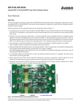
Figure 7 Measurement
There are few ways to apply the input signal into the evalboard:
Apply input current signal with Shunt Resistor
One example to select the shunt resistor value is shown below:
If maximum rms current through motor = 100A, 20 percent overloads during normal operation, then, peak current is 170 A
(= 100 × 1.414 × 1.2). Recommended maximum input voltage for ACPL-C799 = ±50mV.
Shunt resistor value = V/I = 50mV/170A ≈ 0.3m
Power dissipation = I
2
× R = (100)
2
× 0.3m = 3W
The shunt resistor mounting pad is designed to accommodate various shunt resistor package types. The Kelvin connection
PCB trace connects from the center of the pad to the inputs of ACPL-C799 through the anti-aliasing filters (AAFs). Connecting
from the center of the pads is usually the optimum location for most shunt resistor designs. The evalboard also provides pads
P1 and P2 for soldering thick cables to the motor driving board.
Apply input voltage signal without shunt resistor
Connect the audio cable with the audio 3.5-mm jack connected to either a PC, smart phone, tablet, MP3 player, or any kind of
audio player device. Then, connect the crocodile clips to the shunt resistor mounting pads.
By checking the 1kHz sine test signal, you can supply a 1 kHz sine wave voltage signal into the evaluation board. Other
methods include running any of the three sine wave files provided from a music player software program in audio player
devices as described previously. Adjust the volume until the signal level is near ±50mV or ±20,000 ADC counts for best
SNR/SNDR performance.
The performance of SNR/SNDR is dependent on a few factors:
The evalboard
The sigma-delta modulator used, in this case, the ACPL-C799
Input signal frequency used
The decimation ratio, which can be set at the application GUI to 256, 128, 64, or 32.
The input signal level. ACPL-C799 recommended input voltage range is from –50mV to 50mV. To achieve the best
SNR/SNDR, it is recommended to design the maximum input signal range near to ±50mV (selection of input current range
and shunt resistor value).
The input signal source.
Table 2 shows a comparison of the SNR/SNDR performance between audio signal source coming from a laptop and a smart
phone.
Broadcom
- 7 -
ACPL-C799 Evaluation Kit Board
User Guide
Measurement
Lab bench test: Apply input voltage signal from a function generator with 1 shunt resistor mounted on the input of
evaluation board.
When a voltage signal is sourced from a function generator to the evaluation board without a shunt resistor connected as
shown in Figure 8, input bias current of about 0.18mA from the ACPL-C799 will cause a 9mV offset on the function generator
output due to the 50 source impedance of the function generator.
Figure 8 Sourcing the Voltage Signal from a Function Generator to the Evaluation Board without a Shunt Resistor Connected
A more accurate method to measure the performance of the ACPL-C799 evaluation board is to connect a 1 shunt resistor,
then supply the voltage signal from a function generator that can drive sufficient current through the 1 shunt resistor until
an input signal level of ±50mV is reached. One such function generator is the ultra low distortion DS360 function generator
from Standford Research Systems.
Table 3 shows the SNR/SNDR performance using this method.
If such a function generator is not available, it is best to connect an actual shunt resistor and connect to customer's current sensing
system directly.
Table 2 SNR/SNDR Comparison
ACPL-C799 Board
Audio Signal from Dell Lattitude E7440 Laptop Audio Signal from Samsung Galaxy S6
signal freq=1kHz signal freq =500Hz signal freq =1kHz signal freq =500Hz
SNDR(dB) SNR(dB) SNDR(dB) SNR(dB) SNDR(dB) SNR(dB) SNDR(dB) SNR(dB)
Clock freq = 10MHz 67.55 68.44 66.27 68.06 72.31 74.26 72.05 74.76
Table 3 SNR/SNDR Performance
ACPL-C799 Board
DS360 Stanford Research Systems Ultra Low Distortion Function
Generator
signal freq=1kHz signal freq =500Hz
SNDR(dB) SNR(dB) SNDR(dB) SNR(dB)
Clock freq = 10MHz 74.53 77.42 74.97 78.35
Broadcom
- 8 -
ACPL-C799 Evaluation Kit Board
User Guide
PCB Modifications
PCB Modifications
1. Vdd1 is supplied from the 5V/5V isolated dc/dc converter. You can also supply Vdd1 from a 9V battery through the
L78L05ACUTR LDO regulator. To do that, ensure that R45 is disconnected.
2. The ACPL-C799 Vdd2 is supplied from the 3.3V regulator. If you need to check the performance or troubleshoot the ACPL-C799
component only at Vdd2=5V, you can mount a 0 R47 resistor. In this instance, the Vdd2 is supplied directly from the USB
power, 5VCC. Note that you have to remove R18, R19, and R20 because the FPGA I/O pins may not be able to take 5V.
3. The green LED1 signals the detection of ACPL-C799.
4. LED2, LED3, and LED4 are not defined. If you want to modify the FPG, you can use these LED indicators for other functions.
5. The H1 and H2 connector pins are physically connected to the FPGA. If you want to modify the FPGA, you can make use of
these connector pins for input (I/P) or input/output (I/O).
Troubleshooting
1. After switching on SW1, if the green DONE LED does not come on, reset the FPGA by pressing SW2 once. If the problem still
does not go away, perform a full board reset by pressing SW3 once.
2. Each evalboard sent to the customer is functionally checked and tested. If the problem does not go away, consult a Broadcom
Application Engineer. If need be, Broadcom will send a new board.
Broadcom
- 9 -
ACPL-C799 Evaluation Kit Board
User Guide
Appendix
Appendix
PCB Description
Broadcom
- 10 -
ACPL-C799 Evaluation Kit Board
User Guide
Appendix
Schematic Diagram
Broadcom
- 11 -
ACPL-C799 Evaluation Kit Board
User Guide
Appendix
Broadcom
- 12 -
ACPL-C799 Evaluation Kit Board
User Guide
Appendix
Broadcom
- 13 -
ACPL-C799 Evaluation Kit Board
User Guide
Appendix
PCB Layout
Broadcom
- 14 -
ACPL-C799 Evaluation Kit Board
User Guide
Appendix
For product information and a complete list of distributors, please go to our web
site: www.broadcom.com.
Broadcom, the pulse logo, Connecting everything, Avago Technologies, and the
A logo are the trademarks of Broadcom in the United States, certain other
countries and/or the EU.
Copyright © 2016 Broadcom. All Rights Reserved.
The term "Broadcom" refers to Broadcom Limited and/or its subsidiaries. For
more information, please visit www.broadcom.com.
Broadcom reserves the right to make changes without further notice to any
products or data herein to improve reliability, function, or design.
Information furnished by Broadcom is believed to be accurate and reliable.
However, Broadcom does not assume any liability arising out of the application
or use of this information, nor the application or use of any product or circuit
described herein, neither does it convey any license under its patent rights nor
the rights of others.
pub-005678 – May 13, 2016
  • Page 1 1
  • Page 2 2
  • Page 3 3
  • Page 4 4
  • Page 5 5
  • Page 6 6
  • Page 7 7
  • Page 8 8
  • Page 9 9
  • Page 10 10
  • Page 11 11
  • Page 12 12
  • Page 13 13
  • Page 14 14
  • Page 15 15

Broadcom ACPL-C799 User manual

Type
User manual

Broadcom ACPL-C799 Evaluation Kit Board: Isolated Sigma-Delta Modulator. An innovative solution for converting analog signals to high-speed single-bit data streams through sigma-delta oversampling modulation technology. With an impressive internal speed of 10 MHz, this kit offers precise data encoding and transmission across an isolated boundary, ensuring reliable data recovery and decoding. The result is a high-speed digital data stream of ones and zeros that accurately represents the original analog signal information.

Ask a question and I''ll find the answer in the document

Finding information in a document is now easier with AI