Page is loading ...

Broadcom Proprietary. Not for distribution outside the company
- 1 -
Description
SiC devices including SiC MOSFET and SiC Schottky diodes are
recognized as next-generation wide-bandgap devices. They
can provide fast switching with minimized loss compared to
conventional Si devices and improve overall system efficiency.
Higher current switching and higher frequency switching
reduce the overall system size and costs. The technical benefits
coupled with lower costs have increased the fast adoption of
SiC power semiconductors in applications like industrial motor
control, induction heating and industrial power supplies, and
renewable energy.
Broadcom gate-drive optocouplers are used extensively with
Silicon-based semiconductors IGBT and Power MOSFETs can
also be used for SiC operations. Optocouplers are used to
provide reinforced galvanic insulation between the control
circuits from the high voltages and the power semiconductors.
The ability to reject high common mode noise (CMR) prevents
erroneous driving of the SiC power semiconductors during
high-frequency switching.
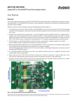
Figure 1 Three-Phase 15 kW SiC Inverter by NSOLUTION
The three-phase 15 kW SiC Inverter designed by NSOLUTION is
meant to demonstrate the high performance of Wolfspeed
(CREE) 1200V/90A SiC MOSFET (C2M0025120D) and SiC
Schottky diodes (C4D40120D). The inverter also includes gate
optocouplers ACPL-P349 for driving the SiC MOSFET,
ACPL-C87A for DC voltage detection, and ACPL-C79A for
three-phase AC-current measurements. The basic block
diagram is shown in Figure 2.
ACPL-P349/C87A/C79A
Wolfspeed(CREE) SiC MOSFET C2M0025120D and
Diode C4D40120D
Reference Design

Broadcom Proprietary. Not for distribution outside the company
- 2 -
ACPL-P349/C87A/C79A Reference Design
Figure 2 SiC Inverter Block Diagram
The reference design shown in Figure 2 describes the functions
and basic operation of optocouplers, ACPL-P349, C87A, and
C79A used in the three-phase SiC inverter. For ordering info,
detailed operation, board configuration, schematic, and other
information, contact NSOLUTION by e-mail
(contact@nsolution) or by web (http://nsolution.co.jp/).
SiC Inverter Features and Operations
As shown in Figure 3, the inverter uses a six-gate drive
optocoupler ACPL-P349 to drive the SiC MOSFET directly in the
three-phase full bridge topology. The ACPL-P349 is a basic gate
driver optocoupler used to isolate and drive the SiC MOSFET
operating at high DC bus voltage. It has a rail-to-rail output
with 2.5A maximum output current to provide fast switching
with high voltage and high driving current to efficiently and
reliably turn on and off the SiC MOSFET. The ACPL-P349 is one
of the industry's fastest with the maximum propagation delay
less than 110 ns and typical rise and fall times around 8 ns. A
very high CMR of 70 kV/μs is required to isolate high transient
noise and prevent erroneous outputs during high-frequency
operation. It can provide isolation certified by UL1577 for up to
V
ISO
3750 V
RMS
/min and IEC 60747-5-5 for working voltage,
V
IORM
up to 891V
PEAK
.
Three isolation amplifiers, ACPL-C79As, are used to sense the
current of U, V, and W phases. The ACPL-C79A implements a
sigma-delta analog-to-digital converter, chopper-stabilized
amplifiers, and a fully differential circuit topology to provide
low offset and high gain accuracy of ±1%. It operates from a
single 5V supply and provides excellent linearity and dynamic
performance of 60 dB SNR. With 200 kHz bandwidth and 1.6 μs
fast response time, the current sensor captures transients in
short circuit and overload conditions. It has high
common-mode transient (15 kV/μs) and EMI immunity to
provide precision and stability in motor control applications.
A shunt resistor is used to sense the current and measure the
voltage applied to the ACPL-C79A through an RC anti-aliasing
filter. Finally, the differential output of the isolation amplifier is
converted to a ground-referenced single-ended output
voltage with a simple differential amplifier circuit.
The ACPL-C87A is optical isolation amplifiers with 2V input
range and high 1 GΩ input impedance designed for voltage
sensing. A resistive voltage divider is used to scale the
high-voltage DC input to suit the input range of the voltage
sensor. A differential output voltage that is proportional to the
input voltage is created on the other side of the optical
isolation barrier.
The ACPL-C87A has ±1% gain tolerance and operates from a
single 5V supply. It provides excellent linearity and has high
common-mode transient immunity of 15 kV/μs.
Figure 3 SiC Inverter PCB and Connection
A high-voltage DC input of 800V is applied across four film
DC-link 200 μF capacitors. The control circuit is powered by a
single 5V (1A) power supply. The inverter can operate at 15 kW,
I
OUT
≤ 30A
RMS
and a carrier frequency of ≤200 kHz, depending
on the heat sink and ambient temperature.

Broadcom Proprietary. Not for distribution outside the company
- 3 -
ACPL-P349/C87A/C79A Reference Design
Figure 4 SiC Inverter Schematic
Figure 5 SiC Inverter Heat Sink, SiC MOSFETs, and Diodes
Test Measurements
Figure 6 Double Pulse Test Circuit
The double pulse test to confirm the Eon, Eoff, and Erec is done
with the circuit in Figure 6. Test conditions:
DC-link voltage = 800V
Gate Drive Supply = +20V/–5V
RGON = 5Ω
RGOFF = 2.2Ω
Inductor Load = 200 μH

Broadcom Proprietary. Not for distribution outside the company
- 4 -
ACPL-P349/C87A/C79A Reference Design
Figure 7 shows the switching of the SiC MOSFET at 50A (note
the time division is 100 ns/div).
Figure 7 Double Pulse Test Switching Waveforms
Using the same testing conditions, the power loss of drain
current dependency is shown in Figure 8.
Figure 8 Power Loss vs. I
D
of SiC MOSFET
The power loss simulation result is shown in Figure 9 with
10A
RMS
output current for both the SiC MOSFET and equivalent
IGBT. The simulation data depends on the result of the double
pulse test for Eon, Eoff, and Erec as well as the DC
characteristics for MOSFET Vds(ON), diode Vf, and IGBT Vce(sat).
Due to the faster switching of the SiC MOSFET, the device has
lower loss compared to IGBT at a high carrier frequency. This is
useful in high frequency applications including motor control,
battery charging, and power supply switching (reducing the
system size and costs).
Figure 9 Power Loss Comparison of SiC MOSFET and IGBT as
Carrier Frequency Dependency

For product information and a complete list of distributors, please go to our web
site: www.broadcom.com.
Broadcom, the pulse logo, Connecting everything, Avago Technologies, Avago,
and the A logo are among the trademarks of Broadcom and/or its affiliates in the
United States, certain other countries and/or the EU.
Copyright © 2017 by Broadcom. All Rights Reserved.
The term "Broadcom" refers to Broadcom Limited and/or its subsidiaries. For
more information, please visit www.broadcom.com.
Broadcom reserves the right to make changes without further notice to any
products or data herein to improve reliability, function, or design.
Information furnished by Broadcom is believed to be accurate and reliable.
However, Broadcom does not assume any liability arising out of the application
or use of this information, nor the application or use of any product or circuit
described herein, neither does it convey any license under its patent rights nor
the rights of others.
ACPL-P349-CxxA-RM100 – April 27, 2017
/