Page is loading ...

1
Revision F
Released 02/17
LP0890
User Manual
PAX2C – 1/8 DIN Temperature/
Process PID Controller
With FlexBus™

22
SAFETY SUMMARY
All safety related regulations, local codes and instructions that appear in this
literature or on equipment must be observed to ensure personal safety and to
prevent damage to either the instrument or equipment connected to it. If
equipment is used in a manner not specified by the manufacturer, the protection
provided by the equipment may be impaired. Do not use this controller to
directly command motors, valves, or other actuators not equipped with
safeguards. To do so can be potentially harmful to persons or equipment in the
event of a fault to the controller.
CAUTION: Risk of Danger.
Read complete instructions prior to
installation and operation of the unit.
CAUTION: Risk of electric shock.
C
US LISTED
U
L
R
3RSD
PROCESS CONTROL EQUIPMENT
Warning: Exposed line voltage exists on the circuit boards. Remove
all power to the controller and load circuits before accessing inside
of the controller.

3
Table Of COnTenTs
Ordering Information ........................................................4
Using This Manual ..........................................................5
Crimson Programming Software ...............................................5
General Controller Specifications...............................................6
Option Cards ..............................................................8
1.0 Installing the Controller ..................................................10
2.0 Setting the Jumpers ....................................................10
3.0 Installing Option Cards ..................................................11
4.0 Wiring the Controller ....................................................11
5.0 Reviewing the Front Buttons and Display....................................13
6.0 Programming The PAX2C................................................14
6.1 Input Programming (INPt) ................................................16
6.2 Output Programming (Out) ................................................20
6.3 Display Programming (dISP) ..............................................23
6.4 PID Programming (Pid) ..................................................31
Operation Overview ........................................................36
Control Mode Explanations ..................................................36
Pid Control Overview . . . . . . . . . . . . . . . . . . . . . . . . . . . . . . . . . . . . . . . . . . . . . . . . . . . . . . .37
Remote Setpoint Control Overview ............................................38
Auto-Tune Explanations .....................................................40
6.5 Alarm Programming (ALr) ................................................42
6.6 Port Programming (Port) .................................................44
Serial Communications Overview .............................................46
PAX2C FREQUENTLY USED MODBUS REGISTERS .............................47
6.7 Factory Service Operations (FACt) ..........................................51
7.0 Programming The FlexCard ..............................................53
7.1 PX2FCA0 - Process Input FlexCard ........................................53
7.2 PX2FCA1 - Heater Current Input FlexCard ..................................57
Troubleshooting Guide ......................................................61

4
Ordering infOrmaTiOn
Controller Part Numbers
MODEL NO. DESCRIPTION PART NUMBER
PAX2C
Universal Input Temperature/Process Controller, with FlexBus™, Horizontal PX2C8H00
Universal Input Temperature/Process Controller, with FlexBus™, Vertical PX2C8V00
Option Card and Accessories Part Numbers
TYPE MODEL NO. DESCRIPTION PART NUMBER
Standard
Option Cards
PAXCDS
Dual Relay Digital Output Card PAXCDS10
Quad Relay Digital Output Card PAXCDS20
Quad Sinking Open Collector Digital Output Card PAXCDS30
Quad Sourcing Open Collector Digital Output Card PAXCDS40
Dual Triac/Dual SSR Drive Digital Output Card PAXCDS50
Quad Form C Relay Digital Output Card PAXCDS60 *
PAXCDC
RS485 Serial Communications Card with Terminal Block PAXCDC10
Extended RS485 Serial Communications Card with Dual RJ11 Connector PAXCDC1C
RS232 Serial Communications Card with Terminal Block PAXCDC20
Extended RS232 Serial Communications Card with 9 Pin D Connector PAXCDC2C
DeviceNet Communications Card PAXCDC30
Profibus-DP Communications Card PAXCDC50
PAXCDL Analog Output Card PAXCDL10
FlexBus™
Option Cards
PX2FCA
Process Input/Remote Setpoint Input Card, With Digital Outputs PX2FCA00 *
Heater Current Monitor Input Card, With Digital Outputs PX2FCA10 *
Accessory
CBLUSB USB Programming Cable Type A-Mini B CBLUSB01
RCPX2
Horizontal Replacement Case with knock-out features RCPX2H00
Vertical Replacement Case with knock-out features RCPX2V00
Note: For Modbus communications use an RS485 Communications Output Card and configure communication (tYPE) parameter for Modbus.
* This card is not suitable for use in older PAX2C models. For proper installation, 3 case knock-out features must be present on the top case
surface (horizontal controller) or right case surface (vertical controller). To update a case to include these knock-outs, a replacement case is
available.

5
Crimson
®
software is a Windows
®
based program that allows configuration
of the PAX
®
controller from a PC. Crimson offers standard drop-down menu
commands, that make it easy to program the controller. The controller’s program
can then be saved in a PC file for future use.
Using This manUal
This manual contains installation and programming instructions for the
PAX2C and all applicable option cards. For ease of installation it is recommended
that the Installation Guide received with the controller be used for the
installation process.
Only the portions of this manual that apply to the application need to be read.
Minimally, we recommend that General Controller Specifications, Reviewing
the Front Buttons and Display, and Crimson
®
Programming Software portions
of this manual be read in their entirety.
We highly recommend that controller programming be performed using
Crimson programming software. When using Crimson, the programming
portion of this manual serves as an overview of the programming options that
are available through Crimson. The programming section of the manual will
serve to provide expanded explanations of some of the PAX2C programming
features found in Crimson.
For users who do not intend to use Crimson to program their controller, this
manual includes information to provide for a user to program one, or all, of the
programming parameters using the controller’s keypad. Note that due to the
extensive programming features of the PAX2C, complete programming of the
controller using the controller’s keypad is not recommended.
When a FlexCard
™
is installed, additional parameters may be available.
Unique FlexCard parameters are defined in 7.0 Programming the FlexCard.
Parameters identified as FCx that are not defined in the FlexCard programming
portion of the manual function as defined in 6.0 Programming the PAX2C.
To find information regarding a specific topic or mnemonic, it is recommended
that the manual be viewed on a computer and the “find” function be used. The
alternate method of finding information is to identify the programming
parameter involved (Input, Output, Display, PID, Alarm, or Communication)
and review the information contained in the section of the manual that pertains
to that parameter.
CrimsOn PrOgramming sOfTware
PrOgramming Using CrimsOn:
Crimson is included on the Flash Drive that is shipped with the PAX2C. Check for
updates to Crimson at http://www.redlion.net/crimson2.
- Install Crimson. Follow the installation instructions provided by the source from
which Crimson is being downloaded or installed.
- Using a USB Type A-Mini B cable, plug the Mini B end of the cable into the
PAX2C USB Programming Port.
- Plug the other end of the USB cable into an available USB port on the PC.
- Apply power to the PAX2C. If a FlexCard has been removed, or has had the
address changed, error message(s) will need to be resolved before continuing.
See Troubleshooting, on page 61, for error message resolution.
- Start Crimson.
- Click the Crimson “Link” tab.
- Click “Extract…”
o Crimson will extract the current program settings from the PAX2C.
o If the controller has not been programmed, the extracted file will contain
factory settings. Note that the PAX2C factory settings vary based on the
option cards installed.
o Crimson will display a PAX2C with various areas described by the
programming parameters that pertain to the area.
- Double click on the “Analog/User Inputs/F Keys/PID” area.
- Make configuration selections. For information regarding a configuration
selection, hover the curser over the selection area.
- Make configuration selections for each tab that appears across the top. When
completed click “Close”.
- Repeat the configuration selection process for the Display/Alarm Parameters
area, followed by applicable option card programming areas.
- When all programming selections have been made, save the configuration file.
- Download the configuration file to the PAX2C by clicking the “Link” tab and
selecting “Update”.
USB
Programming
Port

6
general COnTrOller sPeCifiCaTiOns
1. DISPLAY: Negative image LCD with tri-color backlight.
The display is divided into seven independently programmable color zones:
Line 1, Line 2, Universal Annunciators (1-4) & Status Mnemonics
Line 1 and 2: 4 digits each line
Display Range: -1999 to 9999
Units - Programmable 3 digit units annunciator
Bar Graph - Programmable 8 segment bar graph
Universal Annunciator 1 thru 4: Programmable 2 digit annunciator
Status Mnemonics: MAN - Controller is in Manual Control Mode
REM – Controller is in Remote Setpoint Mode
Vertical Model Digit Size: Line 1 - 0.51" (13 mm), Line 2 - 0.44" (11.2 mm)
Horizontal Model Digit Size: Line 1 - 0.62" (15.7 mm), Line 2 - 0.47" (12.0 mm)
2. POWER:
AC Power: 40 to 250 VAC, 50/60 Hz, 20 VA
DC Power: 21.6 to 250 VDC, 8 W
Isolation: 2300 Vrms for 1 min. to all inputs and outputs.
3. KEYPAD: 2 programmable function keys, 4 keys total
4. A/D CONVERTER: 24 bit resolution
5. DISPLAY MESSAGES:
“OLOL” - Appears when measurement exceeds + signal range.
“ULUL” - Appears when measurement exceeds - signal range
“Shrt” - Appears when shorted sensor is detected. (RTD range only)
“OPEN” - Appears when open sensor is detected. (TC/RTD range only)
“. . . . ” - Appears when display values exceed + display range.
“- . . . ” - Appears when display values exceed - display range.
6. INPUT CAPABILITIES:
Current Input:
INPUT RANGE
ACCURACY *
(18 to 28°C)
ACCURACY *
(0 to 50°C)
IMPEDANCE
‡
RESOLUTION
± 250 µADC
0.03% of rdg
+ 0.03µA
0.12% of rdg
+ 0.04µA
1.11 KW
0.1µA
± 2.5 mADC
0.03% of rdg
+ 0.3µA
0.12% of rdg
+ 0.4µA
111 W
1µA
± 25 mADC
0.03% of rdg
+ 3µA
0.12% of rdg
+ 4µA
11.1 W
10µA
± 250 mADC
0.05% of rdg
+ 30µA
0.12% of rdg
+ 40µA
1.1 W
0.1mA
± 2 ADC
0.5% of rdg
+ 0.3mA
0.7% of rdg
+ 0.4mA
0.1 W
1mA
Voltage Input:
INPUT RANGE
ACCURACY *
(18 to 28°C)
ACCURACY *
(0 to 50°C)
IMPEDANCE
‡
RESOLUTION
± 250 mVDC
0.03% of rdg
+ 30µV
0.12% of rdg
+ 40µV
451 KW
0.1mV
± 2.0 VDC
0.03% of rdg
+ 0.3mV
0.12% of rdg
+ 0.4mV
451 KW
1mV
± 10 VDC
0.03% of rdg
+ 3mV
0.12% of rdg
+ 4mV
451 KW
1mV
± 25 VDC
0.03% of rdg
+ 3mV
0.12% of rdg
+ 4mV
451 KW
10mV
± 100 VDC
0.3% of rdg
+ 30mV
0.12% of rdg
+ 40mV
451 KW
0.1V
± 200 VDC
0.3% of rdg
+ 30mV
0.12% of rdg
+ 40mV
451 KW
0.1V
Temperature Inputs:
Scale: °F or °C
Offset Range: -1999 to 9999 display units.
Thermocouple Inputs:
Input Impedance: 20MW
Lead Resisitance Effect: 0.03 µV/W
Max Continuous Overvoltage: 30 VDC
INPUT
TYPE
RANGE
ACCURACY*
(18 to 28 °C)
ACCURACY*
(0 to 50 °C)
STANDARD
WIRE COLOR
ANSI BS 1843
T -200 to 400°C 1.2°C 2.1°C ITS-90
(+) blue
(-) red
(+) white
(-) blue
E -200 to 750°C 1.0°C 2.4°C ITS-90
(+) purple
(-) red
(+) brown
(-) blue
J -200 to 760°C 1.1°C 2.3°C ITS-90
(+) white
(-) red
(+) yellow
(-) blue
K -200 to 1250°C 1.3°C 3.4°C ITS-90
(+) yellow
(-) red
(+) brown
(-) blue
R 0 to 1768°C 1.9°C 4.0°C ITS-90
no
standard
(+) white
(-) blue
S 0 to 1768°C 1.9°C 4.0°C ITS-90
no
standard
(+) white
(-) blue
B
150 to 300°C
300 to 1820°C
3.9°C
2.8°C
5.7°C
4.4°C
ITS-90
no
standard
no
standard
N -200 to 1300°C 1.3°C 3.1°C ITS-90
(+) orange
(-) red
(+) orange
(-) blue
C
(W5/W26)
0 to 2315°C 1.9°C 6.1°C
ASTM
E988-90**
no
standard
no
standard
RTD Inputs:
Type: 3 or 4 wire, 2 wire can be compensated for lead wire resistance
Excitation current: 100 ohm range: 136.5 µA ±10%
10 ohm range: 2.05 mA ±10%
Lead resistance: 100 ohm range: 10 ohm/lead max.
10 ohm range: 3 ohms/lead max.
Max. continuous overload: 30 VDC
INPUT TYPE RANGE
ACCURACY*
(18 to 28 °C)
ACCURACY*
(0 to 50 °C)
STANDARD
**
100 ohm Pt
alpha = .00385
-200 to 850°C 0.4°C 1.6°C IEC 751
100 ohm Pt
alpha = .00392
-200 to 850°C 0.4°C 1.6°C
no official
standard
120 ohm Nickel
alpha = .00672
-80 to 259°C 0.2°C 0.5°C
no official
standard
10 ohm Copper
alpha = .00427
-110 to 260°C 0.4°C 0.9°C
no official
standard
Resistance Inputs:
INPUT
RANGE
ACCURACY *
(18 to 28°C)
ACCURACY *
(0 to 50°C)
COMPLIANCE
MAX CONT.
OVERLOAD
‡
RESOLUTION
100 ohm
0.05% of rdg
+0.03 ohm
0.2% of rdg
+0.04 ohm
0.175 V 30 V 0.1 ohm
999 ohm
0.05% of rdg
+0.3 ohm
0.2% of rdg
+0.4 ohm
1.75 V 30 V 1 ohm
9999 ohm
0.05% of rdg
+1 ohm
0.2% of rdg
+1.5 ohm
17.5 V 30 V 1 ohm
‡ Higher resolution can be achieved via input scaling.
* After 20 min. warm-up, @ 5 samples per second input update rate. Accuracy
is specified in two ways: Accuracy over an 18 to 28ºC and 15 to 75% RH
environment; and Accuracy over a 0 to 50ºC and 0 to 85% RH (non
condensing) environment. The specification includes the A/D conversion
errors, linearization conformity, and thermocouple ice point compensation.
Total system accuracy is the sum of controller and probe errors. Accuracy
may be improved by field calibrating the controller readout at the
temperature of interest.
** These curves have been corrected to ITS-90.

7
7. EXCITATION POWER: Jumper selectable
Transmitter Power: +18 VDC, ± 5% @ 50 mA max.
Reference Voltage: + 2 VDC, ± 2%
Compliance: 1KW load min (2 mA max)
Temperature Coefficient: 40 ppm/ºC max.
Reference Current: 1.05 mADC, ± 2%
Compliance: 10 KW load max.
Temperature Coefficient: 40 ppm/ºC max.
8. USER INPUTS: Two programmable user inputs
Max. Continuous Input: 30 VDC
Isolation To Sensor Input Common: Not isolated.
Logic State: User programmable (UACt) for sink/source (Lo/Hi)
INPUT STATE
(USrACt)
SINK (Lo) SOURCE (Hi)
20KW pull-up to +3.3V 20KW pull-down
Active V
IN
< 1.1 VDC V
IN
> 2.2 VDC
Inactive V
IN
> 2.2 VDC V
IN
< 1.1 VDC
9. CUSTOM LINEARIZATION:
Data Point Pairs: Selectable from 2 to 16
Display Range: -1999 to 9999
Decimal Point: 0 to 0.000
10. MEMORY: Nonvolatile FRAM memory retains all programmable
parameters and display values.
11. ENVIRONMENTAL CONDITIONS:
Operating Temperature Range: 0 to 50 °C
Storage Temperature Range: -40 to 60 °C
Vibration to IEC 68-2-6: Operational 5-150 Hz, 2 g
Shock to IEC 68-2-27: Operational 25 g (10 g relay)
Operating and Storage Humidity: 0 to 85% max. RH non-condensing
Altitude: Up to 2000 meters
12. CERTIFICATIONS AND COMPLIANCES:
CE Approved
EN 61326-1 Immunity to Industrial Locations
Emission CISPR 11 Class A
IEC/EN 61010-1
RoHS Compliant
UL Listed: File #E179259
Type 4X Indoor Enclosure rating (Face only)
IP65 Enclosure rating (Face only)
IP20 Enclosure rating (Rear of unit)
Refer to EMC Installation Guidelines section of the bulletin for additional
information.
13. CONNECTIONS: High compression cage-clamp terminal block
Wire Strip Length: 0.3" (7.5 mm)
Wire Gauge Capacity: 26 to 16 AWG (0.14 to 1.5 mm
2
)
Torque: 4.4-5.3 inch-lbs (0.5-0.6 N-m)
14. CONSTRUCTION: This controller is rated NEMA 4X/IP65 for indoor use
only. IP20 Touch safe. Installation Category II, Pollution Degree 2. One piece
bezel/case. Flame resistant. Synthetic rubber keypad. Panel gasket and
mounting clip included.
15. WEIGHT: 8 oz. (226.8 g)
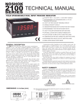
3.80
1.95
0.10
4.14
(96.52)
(49.53)
(2.54)
(105.16)
1.75
(44.45)
3.60
(91.44)
Note: To determine dimensions for
horizontal controllers, swap height
and width. Recommended minimum
clearance (behind the panel) for
mounting clip installation is:
2.1" (53.4) W x 5.5" (140) H.
DIMENSIONS In inches (mm)

8
WARNING: Disconnect all power to the controller before
installing option cards.
Adding Option Cards
The PAX2C controller can be fitted with up to three option cards. FlexCard™
option cards can be placed in any of the three available PAX2C option card slots
and allows for multiple, and duplicate (2 max) FlexCards to be used in a single
controller. Standard option cards require that the option card be placed in a
specific PAX2C option card slot. Standard option card use is also limited to only
one option card for each function type. The function types include Setpoint/
Control (PAXCDS), Communications (PAXCDC), and Analog Output
(PAXCDL). Option cards can be installed initially or at a later date.
ANALOG INPUT FLEXCARDS (PX2FCA)
Analog Input FlexCard option cards can be placed in any of the three available
PAX2C option card slots and allow for multiple, and duplicate (2 max) FlexCards
to be used in a single controller.
BOTH ANALOG INPUT FLEXCARDS
Output Specifications: Four Solid-State NFET outputs
Type: Switched DC, N Channel open drain MOSFET
Current Rating: 1 A DC max
VDS ON: < 0.2 V @ 1 A
VDS Max: 30 VDC
Offstate Leakage Current: 0.5 µA max.
Output Power Supply (+Vout): 18 to 25 VDC @ 40 mA maximum.
Connections:
High compression cage-clamp terminal block (rear terminal block)
Wire Strip Length: 0.3" (7.5 mm)
Wire Gauge Capacity: 26 to 16 AWG (0.14 to 1.5 mm
2
)
Torque: 4.4-5.3 inch-lbs (0.5-0.6 N-m)
Spring-cage-clamp terminal block (top terminal block)
Wire Strip Length: 0.28" (7 mm)
Wire Gauge Capacity: 24-16 AWG (0.2-1.5 mm
2
)
PROCESS INPUT/REMOTE SETPOINT CARD: PX2FCA00
Note: A maximum of two Process Input/Remote Setpoint cards can be
installed in a PAX2C.
Input Ranges: 0 to 10 VDC, 0 to 20 mA DC
A/D Conversion: 16 bit, 6.8 samples/second
Input Specifications:
INPUT RANGE
ACCURACY
@ 0-50°C
INPUT
IMPEDANCE
MAX INPUT
SIGNAL
10 V 0.1% of span 538 KΩ 30 V
20 mA 0.1% of span 10 Ω 150 mA
HEATER CURRENT MONITOR CARD: PX2FCA10
A/D Conversion: 16 bit, 6.8 samples/second
Input Specifications:
Type: Single phase, full wave monitoring of load currents
Input: 100 mA AC output from current transformer (RLC p/n CT005001
or equiv.)
Input Resistance: 5 Ω
Accuracy: ±1.0% full scale, 5 to 100% of range
Frequency: 50 to 400 Hz
Overload: 200 mA (continuous)
Output on time delay for break alarm: 1 second
COMMUNICATION CARDS (PAXCDC)
A variety of communication protocols are available for the PAX2C controller.
Only one PAXCDC card can be installed at a time. Note: For Modbus
communications use RS485 Communications Output Card and configure
communication (tYPE) parameter for Modbus.
SERIAL COMMUNICATIONS CARD: PAXCDC1_ and PAXCDC2_
Type: RS485 or RS232
Communication Type: Modbus ASCII, RLC Protocol (ASCII), and Modbus
RTU
Isolation To Sensor & User Input Commons: 500 Vrms for 1 min.
Not Isolated from all other commons.
Data: 7/8 bits
Baud: 1200 to 38,400
Parity: no, odd or even
Bus Address: Selectable 0 to 99 (RLC Protocol), or 1 to 247 (Modbus
Protocol), Max. 32 controllers per line (RS485)
Transmit Delay: Selectable for 0 to 0.250 sec (+2 msec min)
DEVICENET™ CARD: PAXCDC30
Compatibility: Group 2 Server Only, not UCMM capable
Baud Rates: 125 Kbaud, 250 Kbaud, and 500 Kbaud
Bus Interface: Phillips 82C250 or equivalent with MIS wiring protection per
DeviceNet™ Volume I Section 10.2.2.
Node Isolation: Bus powered, isolated node
Host Isolation: 500 Vrms for 1 minute between DeviceNet™ and controller
input common.
PROFIBUS-DP CARD: PAXCDC50
Fieldbus Type: Profibus-DP as per EN 50170, implemented with Siemens
SPC3 ASIC
Conformance: PNO Certified Profibus-DP Slave Device
Baud Rates: Automatic baud rate detection in the range 9.6 Kbaud to 12 Mbaud
Station Address: 0 to 125, set by rotary switches.
Connection: 9-pin Female D-Sub connector
Network Isolation: 500 Vrms for 1 minute between Profibus network and
sensor and user input commons. Not isolated from all other commons.
DIGITAL OUTPUT CARDS (PAXCDS)
The PAX2C controller has 6 available digital output option cards. Only one
PAXCDS card can be installed at a time. (Logic state of the outputs can be
reversed in the programming.) These option cards include:
DUAL RELAY CARD: PAXCDS10
Type: Two FORM-C relays
Isolation To Sensor & User Input Commons: 2000 Vrms for 1 min.
Contact Rating:
One Relay Energized: 5 amps @ 120/240 VAC or 28 VDC (resistive load).
Total current with both relays energized not to exceed 5 amps
Life Expectancy: 100 K cycles min. at full load rating. External RC snubber
extends relay life for operation with inductive loads
QUAD RELAY CARD: PAXCDS20
Type: Four FORM-A relays
Isolation To Sensor & User Input Commons: 2300 Vrms for 1 min.
Contact Rating:
One Relay Energized: 3 amps @ 240 VAC or 30 VDC (resistive load).
Total current with all four relays energized not to exceed 4 amps
Life Expectancy: 100K cycles min. at full load rating. External RC snubber
extends relay life for operation with inductive loads
QUAD SINKING OPEN COLLECTOR CARD: PAXCDS30
Type: Four isolated sinking NPN transistors.
Isolation To Sensor & User Input Commons: 500 Vrms for 1 min.
Not Isolated from all other commons.
Rating: 100 mA max @ V
SAT
= 0.7 V max. V
MAX
= 30 V
QUAD SOURCING OPEN COLLECTOR CARD: PAXCDS40
Type: Four isolated sourcing PNP transistors.
Isolation To Sensor & User Input Commons: 500 Vrms for 1 min.
Not Isolated from all other commons.
Rating: Internal supply: 18 VDC unregulated, 30 mA max. total
External supply: 30 VDC max., 100 mA max. each output
OPTiOn Cards

9
DUAL TRIAC/DUAL SSR DRIVE CARD: PAXCDS50
Triac:
Type: Isolated, zero crossing detection
Voltage: 260 VAC max., 20 VAC min.
Max Load Current: 1 Amp @ 25°C
0.75 Amp @ 50°C
Total load current with both triacs ON not to exceed 1.5 Amps
Min Load Current: 5 mA
Off State Leakage Current: 1 mA max @ 60 Hz
Operating Frequency: 20-400 Hz
SSR Drive:
Type: Two isolated sourcing PNP Transistors.
Isolation To Sensor & User Input Commons: 500 Vrms for 1 min.
Not Isolated from all other commons.
Rating:
Output Voltage: 18/24 VDC (unit dependent) ± 10%, 30 mA max.
total both outputs
QUAD FORM C RELAY CARD: PAXCDS60
Type: Four FORM-C relays
Isolation To Sensor & User Input Commons: 500 Vrms for 1 min.
Contact Rating:
Rated Load: 3 Amp @ 30 VDC/125 VAC
Total Current With All Four Relays Energized not to exceed 4 amps
Life Expectancy: 100 K cycles min. at full load rating. External RC snubber
extends relay life for operation with inductive loads
LINEAR DC OUTPUT CARD (PAXCDL)
Either a 0/4-20 mA or 0-10 V linear DC output is available from the analog
output option card. The programmable output low and high scaling can be based
on various display values. Reverse slope output is possible by reversing the
scaling point positions.
ANALOG OUTPUT CARD: PAXCDL10
Types: 0 to 20 mA, 4 to 20 mA or 0 to 10 VDC
Isolation To Sensor & User Input Commons: 500 Vrms for 1 min.
Not Isolated from all other commons.
Accuracy: 0.17% of FS (18 to 28 °C); 0.4% of FS (0 to 50 °C)
Resolution: 1/3500
Compliance: 10 VDC: 10 KW load min., 20 mA: 500 W load max.
Powered: Self-powered

10
1.0 insTalling The COnTrOller
2.0 seTTing The JUmPers
INSTALLATION
The PAX2C meets NEMA 4X/IP65 requirements when properly installed.
The controller is intended to be mounted into an enclosed panel. Prepare the
panel cutout to the dimensions shown. Remove the panel latch from the
controller. Slide the panel gasket over the rear of the controller to the back of
the bezel. The controller should be installed fully assembled. Insert the
controller into the panel cutout.
While holding the controller in place, push the panel latch over the rear of the
controller so that the tabs of the panel latch engage in the slots on the case. The
panel latch should be engaged in the farthest
forward slot possible. To achieve a proper
seal, tighten the latch screws evenly until
the controller is snug in the panel
(Torque to approximately 7 in-lbs [79N-
cm]). Do not over-tighten the screws.
INSTALLATION ENVIRONMENT
The controller should be installed in a location that does not exceed the
operating temperature and provides good air circulation. Placing the controller
near devices that generate excessive heat should be avoided.
The bezel should only be cleaned with a soft cloth and neutral soap product.
Do NOT use solvents. Continuous exposure to direct sunlight may accelerate the
aging process of the bezel.
Do not use tools of any kind (screwdrivers, pens, pencils, etc.) to operate the
keypad of the controller.
PANEL
LATCHING
SLOTS
BEZEL
PANEL
GASKET
PANEL
LATCH
LATCHING
TABS
PANEL
MOUNTING
SCREWS
-.00
(92 )
-.0
+.8
3.62
+.03
(45 )
1.77
-.0
+.5
-.00
+.02
-.00
(92 )
-.0
+.8
3.62
+.03
(45 )
1.77
-.0
+.5
-.00
+.02
HORIZONTAL
PANEL CUT-OUT
The PAX2C controller has four jumpers that must be checked and/or changed
prior to applying power. The following Jumper Selection Figures show an
enlargement of the jumper area.
To access the jumpers, remove the controller base from the case by firmly
squeezing and pulling back on the side rear finger tabs. This should lower the
latch below the case slot (which is located just in front of the finger tabs). It is
recommended to release the latch on one side, then start the other side latch.
Warning: Exposed line voltage exists on the circuit boards. Remove
all power to the controller and load circuits before accessing inside
of the controller.
INPUT RANGE JUMPERS
Voltage Input
Two jumpers are used in configuring the controller for voltage/resistance.
The first jumper, T/V, must be in the V (voltage) position. The second jumper is
used to select the proper voltage input range. (This jumper is also used to select
the current input range.) Select a range that is high enough to accommodate the
maximum signal input to avoid overloads. For proper operation, the input range
selected in programming must match the jumper setting.
Current Input
For current input, only one jumper must be configured to select the current
range. This jumper is shared with the voltage input range. To avoid overloads,
select the jumper position that is high enough to accommodate the maximum
signal input level to be applied.
Note: The position of the T/V jumper does not matter when the controller is
in the current input mode.
Temperature Input
For temperature measurement the T/V jumper must be in the T (temperature)
position. For RTD sensors the RTD jumper must also be set.
Resistance Input
Three jumpers are used to configure the resistance input. The T/V jumper
must be in the V (voltage) position, and the excitation jumper must be in the
1.05 mA REF position. The voltage/resistance jumper position is determined by
the input range.
Excitation Output Jumper
This jumper is used to select the excitation range for the application. If
excitation is not being used, it is not necessary to check or move this jumper.
Main
Circuit
Board
REAR TERMINALS
FRONT DISPLAY
I
T
V
RTD
JUMPER
LOCATIONS
100
Finger
Tab
Finger
Tab
V
VEXC
EXCITATION OUTPUT JUMPER
INPUT RANGE JUMPERS
18V @ 50mA
2V REF.
1.05 mA REF.
10 ohm RTD
100 ohm RTD
RTD INPUTS
CURRENT INPUTS
2 A
250 mA
25 mA
2.5 mA
250 µA
TEMPERATURE
VOLTAGE
THERMOCOUPLE/
VOLTAGE
SELECTION
LV - 250mV/2V/100Ω/1KΩ
M - 10V/100V
HV - 25V/200V/10KΩ
VOLTAGE/RESISTANCE
INPUTS
REAR TERMINALS
VERTICAL
PANEL CUT-OUT

11
The option cards are separately purchased optional cards that perform
specific functions. These cards plug into the main circuit board of the controller.
The option cards have many unique functions when used with the PAX2C.
CAUTION: The option and main circuit boards contain static
sensitive components. Before handling the cards, discharge static
charges from your body by touching a grounded bare metal
object. Ideally, handle the circuit boards at a static controlled
clean workstation. Dirt, oil or other contaminants that may
contact the circuit boards can adversely affect circuit operation.
WARNING: Exposed line voltage will be present on the circuit
boards when power is applied. Remove all power to the controller
AND load circuits before accessing the controller.
To Install:
1. For option card specific installation instructions, see the installation
instructions provided with the option card being installed.
2. When handling the main circuit board, hold it by the rear cover. When
handling the option card, hold it by the terminal block.
3. Remove the main assembly from the rear of the case by squeezing both finger
holds on the rear cover and pulling the assembly out of the case. Or use a
small screwdriver to depress the side latches and pull the main assembly out
of the case. Do not remove the rear cover from the main circuit board.
4. Locate the appropriate option card slot location on the main circuit board.
Align the option card terminal block with the slot terminal block position on
the rear cover. Align the option card connector with the main circuit board
option card connector and then press to fully engage the connector. Verify the
tab on the option card rests in the alignment slot on the display board.
5. If installing an option card that includes a terminal block on the top of the
option card, a knock-out on the top of the PAX case will need to be removed
to allow the top terminal block to be inserted later. Locate the shaped
knock-out that aligns with the option slot for which the option card is being
installed. Carefully remove the knock-out, being careful not to remove
additional knock-outs. Trim knock-out tabs (gates) that remain on the case.
The top terminal block on the option card will need to be removed before
completing step 6.
6. Slide the assembly back into the case. Be sure the rear cover latches engage
in the case. If option card includes a top terminal block, install top terminal
block at this time.
3.0 insTalling OPTiOn Cards
Finger
Tab
Finger
Tab
Serial
Communications
Card
Setpoint
Output
Card
Alignment
Slots
Standard Card
Connectors
Analog Output
Card
Main
Circuit
Board
123
FlexCard
Connectors
Slot #
TOP VIEW
WIRING OVERVIEW
Electrical connections are made via terminals located on the back or top of
the controller. All conductors should conform to the controller’s voltage and
current ratings. All cabling should conform to appropriate standards of good
installation, local codes and regulations. It is recommended that the power
supplied to the controller (DC or AC) be protected by a fuse or circuit breaker.
When wiring the controller, compare the numbers embossed on the back of
the controller case to those shown in wiring drawings for proper wire position.
Strip the wire, according to the terminal block specifications (stranded wires
should be tinned with solder). Insert the lead into the correct terminal and then
tighten the terminal until the wire is secure (Pull wire to verify tightness).
EMC INSTALLATION GUIDELINES
Although Red Lion Controls Products are designed with a high degree of
immunity to Electromagnetic Interference (EMI), proper installation and wiring
methods must be followed to ensure compatibility in each application. The type
of the electrical noise, source or coupling method into a unit may be different
for various installations. Cable length, routing, and shield termination are very
important and can mean the difference between a successful or troublesome
installation. Listed are some EMI guidelines for a successful installation in an
industrial environment.
1. A unit should be mounted in a metal enclosure, which is properly connected
to protective earth.
2. Use shielded cables for all Signal and Control inputs. The shield connection
should be made as short as possible. The connection point for the shield
depends somewhat upon the application. Listed below are the recommended
methods of connecting the shield, in order of their effectiveness.
a. Connect the shield to earth ground (protective earth) at one end where the
unit is mounted.
b. Connect the shield to earth ground at both ends of the cable, usually when
the noise source frequency is over 1 MHz.
3. Never run Signal or Control cables in the same conduit or raceway with AC
power lines, conductors, feeding motors, solenoids, SCR controls, and
heaters, etc. The cables should be run through metal conduit that is properly
grounded. This is especially useful in applications where cable runs are long
and portable two-way radios are used in close proximity or if the installation
is near a commercial radio transmitter. Also, Signal or Control cables within
an enclosure should be routed as far away as possible from contactors, control
relays, transformers, and other noisy components.
4. Long cable runs are more susceptible to EMI pickup than short cable runs.
5. In extremely high EMI environments, the use of external EMI suppression
devices such as Ferrite Suppression Cores for signal and control cables is
effective. The following EMI suppression devices (or equivalent) are
recommended:
Fair-Rite part number 0443167251 (RLC part number FCOR0000)
Line Filters for input power cables:
Schaffner # FN2010-1/07 (Red Lion Controls # LFIL0000)
6. To protect relay contacts that control inductive loads and to minimize radiated
and conducted noise (EMI), some type of contact protection network is
normally installed across the load, the contacts or both. The most effective
location is across the load.
a. Using a snubber, which is a resistor-capacitor (RC) network or metal oxide
varistor (MOV) across an AC inductive load is very effective at reducing
EMI and increasing relay contact life.
b. If a DC inductive load (such as a DC relay coil) is controlled by a transistor
switch, care must be taken not to exceed the breakdown voltage of the
transistor when the load is switched. One of the most effective ways is to
place a diode across the inductive load. Most RLC products with solid
state outputs have internal zener diode protection. However external diode
protection at the load is always a good design practice to limit EMI.
Although the use of a snubber or varistor could be used.
RLC part numbers: Snubber: SNUB0000
Varistor: ILS11500 or ILS23000
7. Care should be taken when connecting input and output devices to the
instrument. When a separate input and output common is provided, they
should not be mixed. Therefore a sensor common should NOT be connected
to an output common. This would cause EMI on the sensitive input common,
which could affect the instrument’s operation.
Visit RLC’s web site at http://www.redlion.net/emi for more information on
EMI guidelines, Safety and CE issues as they relate to Red Lion Controls
products.
4.0 wiring The COnTrOller

12
4.1 POWER WIRING
1 2
AC/DC
AC/DC
4.2 VOLTAGE/RESISTANCE/CURRENT INPUT SIGNAL WIRING
IMPORTANT: Before connecting signal wires, the Input Range Jumpers and Excitation Jumper should be verified for proper position.
Process/Current
Signal
(external powered)
Voltage Signal Process/Current Signal
(2 wire requiring 18V
excitation)
Excitation Jumper: 18 V
7 8
+
̶
200VDC MAX.
V-TC-RTD IN
INP COMM
Current Signal (3 wire
requiring 18 V excitation)
Terminal 3: +Volt supply
Terminal 6: +ADC (signal)
Terminal 8: -ADC (common)
Excitation Jumper: 18 V
Voltage Signal (3 wire
requiring 18 V excitation)
Terminal 3: +Volt supply
Terminal 7: +VDC (signal)
Terminal 8: -VDC (common)
Excitation Jumper: 18 V
6
8
2A DC MAX.
I INPUT
INP COMM
Load
-
+
-
+
Resistance Signal
(2 wire requiring
excitation)
Terminal 3: Jumper to
terminal 7
Terminal 7: Resistance
Terminal 8: Resistance
Excitation Jumper:
1.05 mA REF.
T/V Jumper: V position
Voltage/Resistance Input
Jumper: Set per input signal
3 7 8
V EXC
INP COMM
V-TC-RTD-IN
1.05 mA
REF.
10K MAX
Potentiometer Signal as Voltage Input
(3 wire requiring excitation)
Terminal 3: High end of pot.
Terminal 7: Wiper
Terminal 8: Low end of pot.
Excitation Jumper: 2 V REF.
T/V Jumper: V
Voltage/Resistance Input Jumper: 2 Volt
Module 1 Input Range: 2 Volt
Note: The Apply signal scaling style
should be used because the signal
will be in volts.
6 7 83
V-TC-RTD-IN
I INPUT
V EXC
INP COMM
+
3 WIRE TRANSMITTER
_
VoutIout
3 7 8
Rmin=1KΩ
V EXC
INP COMM
V-TC-RTD-IN
2V REF.
2V
INPUT
63
V EXC
I INPUT
2 WIRE
TRANSMITTER
-
+
CAUTION: Sensor input common is NOT isolated from user input common. In order to maintain safe operation of the controller, the sensor input
common must be suitably isolated from hazardous live earth referenced voltages; or input common must be at protective earth ground potential. If not,
hazardous live voltage may be present at the User Inputs and User Input Common terminals. Appropriate considerations must then be given to the
potential of the user input common with respect to earth common; and the common of the isolated option cards with respect to input common.
4.3 TEMPERATURE INPUT SIGNAL WIRING
IMPORTANT: Before connecting signal wires, verify the T/V Jumper is in the T position.
3-Wire RTD
Thermocouple
2-Wire RTD
5
78
RTD EXC
V-TC-RTD-IN
INP COMM
Sense Lead
Jumper
5
78
RTD EXC
V-TC-RTD-IN
INP COMM
Sense Lead
RTD (Excitation)
78
+
̶
V-TC-RTD-IN
INP COMM
CAUTION: Sensor input common is NOT isolated
from user input common. In order to maintain safe
operation of the controller, the sensor input
common must be suitably isolated from hazardous
live earth referenced voltages; or input common
must be at protective earth ground potential. If not,
hazardous live voltage may be present at the User
Inputs and User Input Common terminals.
Appropriate considerations must then be given to
the potential of the user input common with respect
to earth common; and the common of the isolated
option cards with respect to input common.
+
-
+
-
OR
12
AC/DC
AC/DC
12
AC/DC
AC/DC
AC Power
DC Power
The power supplied to the controller shall employ a 15 Amp UL approved circuit breaker for AC input and a 1 Amp, 250 V UL approved fuse for DC input. It shall
be easily accessible and marked as a disconnecting device to the installed controller. This device is not directly intended for connection to the mains without a reliable
means to reduce transient over-voltages to 1500 V.

13
4.4 USER INPUT WIRING
If not using User Inputs, then skip this section. User Input terminals do not need to be wired in order to remain in the inactive state.
Sourcing Logic (UACt Hi)
When the UACt parameter is programmed
to Hi, the user inputs of the controller are
internally pulled down to 0 V with 20 KW
resistance. The input is active when a
voltage greater than 2.2 VDC is applied.
USER COMM
USER 2
USER 1
10 119
OR
Sinking Logic (UACt Lo)
When the UACt parameter is programmed
to Lo, the user inputs of the controller are
internally pulled up to +3.3 V with 20 KW
resistance. The input is active when it is
pulled low (<1.1 V).
10
91
1
+
-
(30V max.)
SUPPLY
V
USER COMM
USER 2
USER 1
OR
4.5 DIGITAL OUTPUT (SETPOINT) WIRING
4.6 SERIAL COMMUNICATION WIRING
4.7 ANALOG OUTPUT WIRING
4.8 FLEXCARD INPUT/OUTPUT WIRING
See appropriate option card bulletin for wiring details.
5.0 reviewing The frOnT bUTTOns and disPlay
DISPLAY LINE 1 (Color Zone 1)
Line 1 consists of a large 4-digit top line display, eight segment bar graph and
a three digit units mnemonic: Values such as Input, Max(HI) & Min (LO) may
be shown on Line 1. The eight segment bar graph may be mapped to values such
as Output Power, Deviation or Setpoints. The three digit units mnemonic
characters can be used to indicate engineering units for the Line 1 display value.
Line 1 is a tri-colored display and may be configured to change color based on
specified alarm/logic configurations.
KEY DISPLAY MODE OPERATION
D Index Line 2 through enabled Line 2 display values
P
Enter full programming mode or access the parameter and
hidden display loops; Press and hold to skip parameters and go
directly to Code or Programming Menu
!
User programmable Function key 1; hold for 3 seconds for user
programmable second function 1*
@
User programmable Function key 2; hold for 3 seconds for user
programmable second function 2*
*Factory setting for F1/F2 and second function F1/F2 is no mode
KEY PROGRAMMING MODE OPERATION
D
Return to the previous menu level (momentary press)
Quick exit to Display Mode (press and hold)
P
Access the programming parameter menu, store selected
parameter and index to next parameter
!
Increment selected parameter value; Hold ! and momentarily
press @ key to increment next decade or D key to increment by
1000’s
@
Decrement selected parameter value; Hold @ and momentarily
press ! key to decrement next decade or D key to decrement
by 1000’s
DISPLAY LINE 2 (Color Zone 2)
Line 2 consists of a 4-digit bottom line display, eight segment bar graph and
a three digit units mnemonic. Values such as Setpoints, Output Power,
Deviation, PID Parameters/Tuning Status, List A/B Status, and Alarm Values
may be shown on the Line 2 display. The eight segment bar graph may be
mapped to values such as Output Power, Deviation or Setpoints. The three digit
units mnemonic characters can be used to indicate engineering units for the Line
2 display value. Line 2 is a tri-colored display and may be configured to change
color based on specified alarm/logic configurations.
Line 2 is also used to view the display loops described in the next section. See
Line 2 parameters in the Display Parameters programming section for
configuration details.
MAN REM
Line 1:
Display, Bar Graph
and Units
(Color Zone 1)
Universal
A
nnunciators 1-4
(Color Zones 3 - 6)
Manual and Remote
Mode Mnemonics
(Color Zone 7)
Display
Bar Graph
Units
Line 2:
Display, Bar Graph
and Units
(Color Zone 2)
F1
F2

14
6.0 PrOgramming The PaX2C
The PAX2C offers three display loops to allow users quick access to needed
information. Display loops provide quick access to selected parameters that can
be viewed and modified on Line 2 without having to enter Full Programming
mode. These values may include: input, max/min, List A/B selection, output
power, PID parameters/control, alarm parameters, setpoint values/selection, and
display intensity and contrast settings.
Main Display Loop
In the Main display loop, the D key is pressed to advance through the selected
Line 2 values. The Line 2 units mnemonics are used to indicate which Line 2
value is currently shown. When in the Main display loop, the Function keys
perform the user function as programmed in the User Input parameter section.
Parameter and Hidden Parameter Display Loops
To utilize the Hidden Parameter display loop, a security code (1-250) must be
programmed. (See Programming Security Code in the Display Parameters
programming section for details.)
The Parameter display loop is accessed by pressing the P key (key must be
pressed twice if displaying a dEnt value). The selected Parameter display loop
values can be viewed and/or changed per the Line 2 Value Access setting
programmed for each available value. The Hidden Parameter display loop
follows the Parameter display loop, and can only be accessed when the correct
security code is entered at the Code prompt. Combining the two parameter loops
provides an area for parameters that require general access and/or protected or
secure access depending on the application needs.
While in the Parameter and Hidden Parameter loops, pressing the D key will
return the controller to the Main display loop. To directly access the Code
prompt, press and hold the P key. This can be done from the Main display loop
or at any point during the Parameter display loop. Also, to directly access Full
Programming mode while in the Hidden Parameter loop, press and hold the P
key to bypass any remaining Hidden Parameter loop values.
line 2 disPlay lOOPs
Pro
NO
P
COdE
1-250
Pro
End
HIDDEN
PARAMETER
DISPLAY
LOOP
PARAMETER
DISPLAY
LOOP
P
P
P
P
P
MAIN DISPLAY LOOP
D
Code 0
PLOC Disabled
Code 1-250
PLOC N/A
Full Programming
P
P
Held
Held
Code 0
PLOC Enabled
DISPLAY LOOP
VALUE
CHANGE
dEnt
P
Wrong
code
entered
PARAMETER
DISPLAY
LOOP
P
P
DISPLAY LOOP
VALUE
CHANGE
dEnt
P
PARAMETER
DISPLAY
LOOP
P
P
DISPLAY LOOP
VALUE
CHANGE
dEnt
P
Held
UNIVERSAL ANNUNCIATOR ZONES (Color Zone 3-6)
The PAX2C has four programmable universal annunciator zones (UAn1-UAn4).
Each zone has a user-defined two digit annunciator mnemonic to suit a variety
of applications. Universal annunciator zones are tri-colored and may be
configured to change color based on specified alarm/logic conditions.
MANUAL/REMOTE MNEMONIC (Color Zone 7)
‘MAN’ - Flashes when the controller or a FlexCard is operating in manual
PID Control mode
‘REM’ - Flashes when the controller or a FlexCard is operating in Remote
Setpoint mode.
The Mnemonic zone is tri-colored and may be configured to change color
based on specified alarm/logic conditions.
It is highly recommended that controller programming be performed using
Crimson programming software. Program settings should be saved or recorded
as programming is performed.
BASIC/ADVANCED CONFIGURATION MODE
The PAX2C provides two different user selectable configuration modes:
Basic Configuration Mode (bSIC)
Basic is the default mode. When the PAX2C is configured in this mode, a
maximum of four alarms are supported and no mapped backlight color changes
are available. Default backlight colors are user selectable.
Advanced Configuration Mode (AdUC)
In the Advanced mode, a maximum of sixteen alarms are supported and all
backlight color configuration menu parameters are enabled. Select this mode
when you require more than four alarms or where process dependent display
color changes are desired.
FULL PROGRAMMING ENTRY
Full Programming is entered by pressing and holding the P key. Full
Programming will be accessible unless the controller is programmed to use the
Hidden Parameter loop or PLOC is active with CodE = 0. In this case, programming
access will be limited by a security code and/or a hardware program lock. (Refer
to the previous section for details on Line 2 display loops and limited
programming access.) Full Programming permits all parameters to be viewed
and modified. In this mode, the front panel keys change to Programming Mode
Operations and certain user input functions are disabled.
MAIN PROGRAMMING LOOP
The Main Programming Loop provides access to seven main programming
modules. These modules group together functionally related parameters. The !
and @ keys are used to select the desired programming module. The displayed
module is entered by pressing the P key.
PARAMETER PROGRAMMING SELECTION LOOP
After entering (P key) a main programming module selection, the user gains
access to the programming selection loop. This loop breaks down the specific
module into more specific and detailed parameter groups. For example, the
Input Parameter module provides for selection of Analog and User input
parameters. The ! and @ keys are used to select the desired parameter
programming selection. The parameter programming selection is entered by
pressing the P key.
PARAMETER PROGRAMMING LOOP
After entering (P key) a parameter in the parameter programming selection
loop, the Parameter Programming Loop is entered. This loop is a sequence of
parameters that can be changed/programmed. The P key is pressed to enter the
program selection and advance to the next parameter. After advancing through
all the parameters in the Parameter Programming Loop, the display returns to
the Parameter Programming Selection Loop.
If a parameter selection has been changed, the P key must be pressed in order
to save the change. Pressing the D key before pressing the P key will cause the
unit to abort a selected change.

15
F1
F2
F1
F2
F1
F2
F1
F2
F1
F2
F1
F2
D
P
D
P D
Analog Input Setup
Parameters
User Input/Function Key
Parameters
D
D
D
Factory Service
Operations
Display Loop
2 seconds
Pro
NO
Pro
INPt
INPt
ANLG
INPt
USEr
Pro
Out
Pro
dISP
F1
F2
P
D
Analog Output Setup
Parameters
Digital Output Setup
Parameters
Out
CdL
Out
CdS
F1
F2
D
Pro
Port
D
Pro
FACt
Pro
End
F1
F2
P
D
USB Configuration
Parameters
Serial Communications
Parameters
Port
USb
Port
SErL
F1
F2
F1
F2
P
D
Display - General
Configuration Parameters
Display - Zone
Configuration Parameters
dISP
CNFG
dISP
ZONE
F1
F2
Display - Line 2
Parameter Value Access
Display - Min/Max
Configuration Parameters
dISP
LOCS
dISP
HILO
F1
F2
Display - Security Code
Configuration Parameters
dISP
COdE
Pro
Pid
F1
F2
F1
F2
P
D
F1
F2
D
Pro
ALr
P
D
PID Control
Parameters
PID Setpoint
Parameters
Pid
CtrL
Pid
SP
F1
F2
PID
Parameters
Output Power
Parameters
Pid
Pid
Pid
PWr
F1
F2
On/Off
Parameters
Pid
ONOF
F1
F2
PID Tuning
Parameters
Pid
tunE
Alarm
Parameters
SLCt
AL-x
MAIN
PROGRAMMING
LOOP
PARAMETER
PROGRAMMING
SELECTION LOOP
PARAMETER
PROGRAMMING
LOOP
6.1
6.2
6.3
6.4
6.5
6.6
6.7
P
Section
6.1.1
6.1.2
6.2.1
6.2.2
6.3.1
6.3.2
6.3.3
6.3.4
6.3.5
6.4.1
6.4.2
6.4.3
6.4.4
6.4.5
6.4.6
6.5.1
6.6.1
6.6.2
ª If a FlexCard option card is installed, a hardware selection programming
loop will appear between the Main Programming Loop and the
Parameter Programming Selection Loop. See Section 7.0, Programming
the FlexCard, for more details.
SELECTION/VALUE ENTRY
For each parameter, the top line display shows the parameter while the
bottom line shows the selections/value for that parameter. The ! and @
keys are used to move through the selections/values for the parameter.
Pressing the P key, stores and activates the displayed selection/value. This
also advances the controller to the next parameter.
Numerical Value Entry
The ! and @ keys will increment or decrement the parameter value.
When the ! or @ key is pressed and held, the value automatically scrolls.
The longer the key is held the faster the value scrolls.
For large value changes, press and hold the ! or @ key. While holding
that key, momentarily press the opposite arrow key ( @ or !) to shift
decades (10’s 100’s, etc), or momentarily press the D key and the value
scrolls by 1000’s as the arrow key is held. Releasing the arrow key removes
the decade or 1000’s scroll feature. The arrow keys can then be used to make
small value changes as described above.
PROGRAMMING MODE EXIT
To exit the Programming Mode, press and hold the D key (from anywhere
in the Programming Mode) or press the P key with Pro NO displayed. This will
commit stored parameter changes to memory and return the controller to the
Display Mode. If a parameter was just changed, the P key must be pressed
to store the change before pressing the D key. (If power loss occurs before
returning to the Display Mode, verify recent parameter changes.)
PROGRAMMING TIPS
It is highly recommended that controller programming be performed using
Crimson programming software. If lost or confused while programming
using the keypad method, press and hold the D key to exit programming
mode and start over. Program settings should be saved or recorded as
programming is performed. When programming is downloaded or completed,
lock out programming with a user input or lock-out code.
Factory Settings may be completely restored in the Factory Service
Operations module. This is useful when encountering programming
problems.
In Programming Menu:
Top line is green to indicate main programming loop.
Top line is orange to indicate parameter programming selection is
available.
Top line is red to indicate a changeable parameter is being viewed.

16
6.1 inPUT PrOgramming (INPt)
INPUT SELECT
ANLG USEr
Select the Input to be programmed.
Enable
Square
Root
Input
Update
Rate
Decimal
Resolution
Rounding
Increment
Offset
Value
Digital
Filter
Scaling
Points
INPt
P2C
ANLG
Root
INP
NO
RAtE
INP
20
SPS
dCPt
INP
0.O
Rnd
INP
0.1
OFSt
INP
0.0
FLtr
INP
1.O
SEC
PNtS
INP
2
Scaling
Style
StYL
INP
KEY
Input n
Value
INPt
INP
0.0
1
Display n
Value
dISP
INP
0.O
1
Enable
Scale
List
SLSt
INP
NO
Input
Type
Temperature
Scale
Ice Point
Compensation
tYPE
INP
tc-J
SCAL
INP
°F
ICE
INP
ON
Process Type Only
Temperature Type Only
This section details the programming for the analog input.
INPUT TYPE
250 uA 2 U 1k RES tc-r r392
2.5 mA 10 U 10k RES tc-S r672
25 mA 25 U tc-t tc-b r427
250 mA 100 U tc-E tc-n
2 A 200 U tc-J tc-C
250 mU 100 RESs tc-k r385
Select the desired input type. Shaded selections indicate temperature input
types.
TEMPERATURE SCALE
°F °C
Select the temperature scale. If changed, those parameters that
relate to the temperature scale should be checked.
ICE POINT COMPENSATION
For TC Input Range Selection only.
ON OFF
This parameter turns the internal ice point compensation on or off.
Normally, the ice point compensation is on. If using external
compensation, set this parameter to off. In this case, use copper leads
from the external compensation point to the controller.
SQUARE ROOT
YES NO
This parameter allows the controller to be used in applications in
which the measured signal is the square of the process value (PU).
This is useful in applications such as the measurement of flow with
a differential pressure transducer.
Example: It is necessary to square root linearize the output of a differential
pressure transmitter to indicate and control flow. The defining equation is F
= 278 ÖΔP , where ΔP = 0 - 500 PSI, transmitted linearly by a 4 - 20 mA
transducer. At full flow rate ( ΔP = 500 PSI), the flow is 6216 ft
3
/h. The
following scaling information is used with the controller:
dCPt = 0 INPt1 = 4.00 mA
Root = YES dISP2 = 6216 ft
3
/hr
dISP1 = 0 ft
3
/hr INPt2 = 20.00 mA
As a result of the scaling and square root linearization, the following
represents the readings at various inputs:
Delta P
(PSI)
Transmitter
(mA)
Flow
(ft
3
/hr)
0.00 4.00 0
15.63 4.50 1099
31.25 5.00 1554
62.50 6.00 2198
125.00 8.00 3108
187.50 10.00 3807
250.00 12.00 4396
312.50 14.00 4914
375.00 16.00 5383
437.50 18.00 5815
500.00 20.00 6216
tYPE
INP
tc-J
SCAL
INP
°F
ICE
INP
ON
Root
INP
NO
6.1.1 analOg inPUT ParameTers (ANLG)
F1
F2
P
D
Pro
NO
Pro
INPt
INPt
P2C
ANLG
Temperature type only
Process type only
ª If a FlexCard option card is installed, a hardware selection programming
loop will appear between the Main Programming Loop and the
Parameter Programming Selection Loop. See Section 7.0, Programming
the FlexCard, for more details.

17
INPUT UPDATE RATE (/SEC)
5 10 20 40
Select the input update rate (conversions per second). The
selection does not affect the display update rate, however it does
affect alarm and analog output response time. The default factory
setting of 20 is recommended for most applications. Selecting a fast
update rate may cause the display to appear very unstable.
DECIMAL RESOLUTION (Display Units)
0 to 0.0 (temperature)
0 to 0.000 (process)
Select desired display resolution. The available selections are
dependent on the Input Type selected (tYPE).
ROUNDING INCREMENT
1 2 5 10
20 50 100
Rounding selections other than one, cause the Input Display to
‘round’ to the nearest rounding increment selected (ie. rounding of
‘5’ causes 122 to round to 120 and 123 to round to 125). Rounding
starts at the least significant digit of the Input Display. Remaining
parameter entries (scaling point values, setpoint values, etc.) are not automatically
adjusted to this display rounding selection.
OFFSET VALUE
-1999 to 9999
The process value can be corrected with an offset value. This can
be used to compensate for probe errors, errors due to variances in
probe placement or adjusting the readout to a reference thermometer.
DIGITAL FILTER
0.0 to 25.0 seconds
The digital filter setting is a time constant expressed in tenths of a
second. The filter settles to 99% of the final display value within
approximately 3 time constants. This is an Adaptive Digital Filter
which is designed to steady the Input Display reading. A value of ‘0’
disables filtering.
SCALING POINTS
2 to 16
Linear - Scaling Points (2)
For linear processes, only 2 scaling points are necessary. It is
recommended that the 2 scaling points be at opposite ends of the
input signal being applied. The points do not have to be the signal
limits. Display scaling will be linear between and continue past the
entered points up to the limits of the Input Signal Jumper position. Each scaling
point has a coordinate-pair consisting of an Input Value (INPt n) and an
associated desired Display Value (dISP n).
Nonlinear - Scaling Points (Greater than 2)
For non-linear processes, up to 16 scaling points may be used to provide a
piece-wise linear approximation. (The greater the number of scaling points used,
the greater the conformity accuracy.) The Input Display will be linear between
scaling points that are sequential in program order. Each scaling point has a
coordinate-pair consisting of an Input Value (INPt n) and an associated desired
Display Value (dISP n). Data from tables or equations, or empirical data could be
used to derive the required number of segments and data values for the
coordinate pairs. In the Crimson software, several linearization equations are
provided to help calculate scaling points.
SCALING STYLE
KEY key-in data
APLY apply signal
If Input Values and corresponding Display Values are known, the
Key-in (KEY) scaling style can be used. This allows scaling without
the presence of the input signal. If Input Values have to be derived
from the actual input signal source or simulator, the Apply (APLY)
scaling style must be used.
INPUT VALUE FOR SCALING POINT 1
-1999 to 9999
For Key-in (KEY), enter the known first Input Value by using the
! or @ arrow keys. (The Input Range selection sets up the decimal
location for the Input Value). For Apply (APLY), the existing
programmed value will appear. If this is acceptable, press the P key
to save and continue to the next parameter. To update/program this
value, apply the input signal that corresponds to Scaling Point 1, press @ key
and the actual signal value will be displayed. Then press the P key to accept this
value and continue to the next parameter.
DISPLAY VALUE FOR SCALING POINT 1
-1999 to 9999
Enter the first coordinating Display Value by using the arrow keys.
This is the same for KEY and APLY scaling styles. The decimal point
follows the dCPt selection.
INPUT VALUE FOR SCALING POINT 2
-1999 to 9999
For Key-in (KEY), enter the known second Input Value by using the
! or @ arrow keys. For Apply (APLY), the existing programmed
value will appear. If this is acceptable, press the P key to save and
continue to the next parameter. To update/program this value, apply
the input signal that corresponds to Scaling Point 2, press @ key and the actual
signal value will be displayed. Then press the P key to accept this value and
continue to the next parameter. (Follow the same procedure if using more than
2 scaling points.)
DISPLAY VALUE FOR SCALING POINT 2
-1999 to 9999
Enter the second coordinating Display Value by using the ! or @
arrow keys. This is the same for KEY and APLY scaling styles. (Follow
the same procedure if using more than 2 scaling points.)
ENABLE SCALE LIST
NO YES
NO
– Scaling points from List A are active without regard to
List A/List B selection
YES
– Enables List B scaling points. When List A is
selected, List A scaling points are active. When List B
is selected, List B scaling points are active.
RAtE
INP
20
SPS
dCPt
INP
0.0
Rnd
INP
0.1
OFSt
INP
0.0
FLtr
INP
1.0
SEC
PNtS
INP
2
StYL
INP
KEY
INPt
INP
0.000
1
dISP
INP
0.0
1
INPt
INP
1.000
2
dISP
INP
100.0
2
SLSt
INP
NO
Temperature type only
Process type only

18
INPt
P2C
USEr
USEr
P2C
UACt
USER INPUT ACTIVE STATE
Lo Hi
Select the desired active state for the User Inputs.
Select Lo for sink input, active low. Select Hi for
source input, active high. The active state of the
user input must be selected before programming the
function of the specific user input.
USER INPUT/FUNCTION KEY SELECT *
NONE PLOC ILOC trnF
SPSL RSPt PSEL SPrP
d-HI r-HI d-Lo r-Lo
r-HL r-AL dLEU dISP
LISt Prnt
The two user inputs are individually programmable to perform specific
control functions. While in the Display Mode or Program Mode, the function is
executed the instant the user input transitions to the active state. The front panel
function keys, ! and @, are also individually programmable to perform
specific control functions. While in the Display Mode, the primary function is
executed the instant the key is pressed. Holding the function key for three
seconds executes a secondary function. It is possible to program a secondary
function without a primary function.
In most cases, if more than one user input and/or function key is programmed
for the same function, the maintained (level trigger) actions will be performed
while at least one of those user inputs or function keys are activated. The
momentary (edge trigger) actions will be performed every time any of those user
inputs or function keys transition to the active state.
Note: In the following explanations, not all selections are available for both
user inputs and front panel function keys. Displays are shown with each
selection. Those selections showing both displays are available for both. If a
display is not shown, it is not available for that selection. USrx will represent
both user inputs. Fx will represent both function keys and second function keys.
NO FUNCTION
No function is performed if activated. This is the
factory setting for all user inputs and function keys.
FULL PROGRAMMING LOCK-OUT
When activated, full programming is locked-out (maintained
action). A security code can be configured to allow programming
access during lock-out.
INTEGRAL ACTION LOCK
When activated, the Integral Action Lock of the PID
computation is disabled (USrx = maintained action; Fx =
toggle).
AUTO/MANUAL MODE
When activated, the controller is placed in manual PID
Control mode (USrx = maintained action; Fx = toggle). The
output is “bumpless” when transferring to/from either
operating mode.
SETPOINT SELECTION
When activated, the controller uses Setpoint 2 (SP2) as
the active setpoint value (USrx = maintained action; Fx =
toggle).
REMOTE SETPOINT TRANSFER
When activated, the controller uses Remote Setpoint
(RSP) as the active setpoint value (USrx = maintained
action; Fx = toggle). This selection requires proper
configuration of Remote Setpoint parameters in the PID
SP Parameter Programming Loop.
PID PARAMETER SELECTION
When activated, the controller uses the Alternate P, I,
D, and filter values for control (USrx = maintained action;
Fx = toggle). The controller initiates a “bumpless”
transfer during each transfer in an effort to minimize any
output power fluctuation.
USEr
P2C
UACt
UACt
FNC
Lo
USEr
P2C
USr1
USr1
FNC
NONE
USrx
FNC
NONE
Fx
FNC
NONE
USrx
FNC
PLOC
P2C
USrx
FNC
ILOC
P2C
Fx
FNC
ILOC
P2C
USrx
FNC
trnF
P2C
Fx
FNC
trnF
P2C
USrx
FNC
SPSL
P2C
Fx
FNC
SPSL
P2C
USrx
FNC
RSPt
P2C
Fx
FNC
RSPt
P2C
USrx
FNC
PSEL
P2C
Fx
FNC
PSEL
P2C
6.1.2 User inPUT/fUnCTiOn Key ParameTers (USEr)
USER PROGRAM MENU SELECTION
UACt USr1 USr2 F1
F2 SCF1 SCF2
Select the user program menu to be configured.
UACt
= User Input Active State
USr1
= User Input 1
USr2
= User Input 2
F1
= Function Key 1
F2
= Function Key 2
SCF1
= Second Function Key 1
SCF2
= Second Function Key 2
These selections are only available for user inputs.
* This parameter selection is affected by FlexCard installation. See Section 7.0,
Programming the FlexCard.

19
SETPOINT RAMPING DISABLE
When activated, setpoint ramping is terminated and the
controller will control at the target setpoint (USrx =
maintained action). When user input is deactivated,
setpoint ramping will occur at the next setpoint change.
When the Function key is pressed, setpoint ramping is
terminated and the controller will control at the target
setpoint (Fx = toggle). A second press of the function key
enables setpoint ramping to occur at the next setpoint
change.
SELECT MAXIMUM VALUE DISPLAY
When activated, the Maximum value appears on Line 2 as long as
active (maintained). When the user input is inactive, the previously
selected display is returned. The D or P keys override and disable the
active user input. The Maximum continues to function independent
of the selected display.
RESET MAXIMUM VALUE
When activated, rSEt flashes on the display and the
Maximum value resets to the present Input value
(momentary action). The Maximum function then
continues updating from that value. This selection
functions independent of the selected display.
SELECT MINIMUM VALUE DISPLAY
When activated, the Minimum value appears on Line 2 as long as
active (maintained). When the user input is inactive, the previously
selected display is returned. The D or P keys override and disable the
active user input. The Minimum continues to function independent of
the selected display.
RESET MINIMUM VALUE
When activated, rSEt flashes on the display and the
Minimum value resets to the present Input value
(momentary action). The Minimum function then
continues updating from that value. This selection
functions independent of the selected display.
RESET MAXIMUM AND MINIMUM VALUE
When activated, rSEt flashes and the Maximum and
Minimum readings are set to the present Input value
(momentary action). The Maximum and Minimum
function then continues updating from that value. This
selection functions independent of the selected display.
RESET ALARMS
When activated, the controller will reset active alarms
as configured in the Alarm Mask Selection (ASEL) below
(momentary action).
Basic Mode: 4 Alarms Max
Advanced Mode: 16 Alarms Max
ALARM MASK ASSIGNMENT
Selects the alarms that will be reset when the User Input/
Function key is activated. Any alarm configured as “YES” will
be reset. Please see the Alarms section of the manual for more
information on the alarm reset operation.
ADJUST DISPLAY INTENSITY
When activated, the display intensity changes to the
next intensity level (momentary action).
DISPLAY SELECT
When activated, Line 2 advances to the next enabled
display (momentary action). Displays are enabled in
Display LOCS Parameter Programming Loop.
SELECT PARAMETER LIST
Two lists of input scaling points and alarm values
(including band and deviation) are available. The two lists
are named LStA and LStb. If a user input is used to select
the list then LStA is selected when the user input is not
active and LStb is selected when the user input is active
(maintained action). If a front panel key is used to select
the list then the list will toggle for each key press
(momentary action). The display will indicate which list is active when the list
is changed, at power-up, and when entering Parameter or Hidden Loops if they
contain alarm values. To program the values for List-A and List-B, first
complete the programming of all the parameters. Exit programming and switch
to the other list. Re-enter programming and enter the desired values for the input
scaling points, alarms, band, and deviation if used.
PRINT REQUEST (Communication Type RLC only)
When activated, a print request is performed. The serial
type must be set to RLC for the serial port to process the
request. The data transmitted during a print request and
the serial type is programmed in Section 6.6.2. If the user
input remains active after the transmission is complete
(about 100 msec), an additional transmission occurs. As
long as the user input is held active, continuous
transmissions occur.
USrx
FNC
SPrP
P2C
Fx
FNC
SPrP
P2C
USrx
FNC
d-HI
P2C
USrx
FNC
r-HI
P2C
Fx
FNC
r-HI
P2C
USrx
FNC
d-Lo
P2C
USrx
FNC
r-Lo
P2C
Fx
FNC
r-Lo
P2C
USrx
FNC
r-HL
P2C
Fx
FNC
r-HL
P2C
USrx
FNC
r-AL
P2C
Fx
FNC
r-AL
P2C
ASEL
Un
NO
An
USrx
FNC
dLEU
P2C
Fx
FNC
dLEU
P2C
USrx
FNC
dISP
P2C
Fx
FNC
dISP
P2C
USrx
FNC
LISt
P2C
Fx
FNC
LISt
P2C
USrx
FNC
Prnt
P2C
Fx
FNC
Prnt
P2C
These selections are only available for user inputs.

20
6.2 OUTPUT PrOgramming (Out)
ANALOG OUTPUT TYPE
4-20 0-10 0-20
Enter the analog output type. Verify that correct output type
terminals are wired. Only one range can be used at a time.
ANALOG OUTPUT ASSIGNMENT *
NONE PU HI LO OP SP dEv
Assign the parameter for the analog output to retransmit. Line 2
mnemonic indicates the source from which the parameter value is
derived: PAX2C input (P2C) or FlexCard input (FCx) when installed.
(x = FlexCard address)
NONE
= Output not assigned
PU
= Process Value
HI
= Maximum Display Value
LO
= Minimum Display Value
OP
= Output Power
SP
= Active Setpoint Value (Local or Remote)
dEv
= Deviation from the Setpoint value
ANALOG OUTPUT CUSTOM (Non-Linear) SCALING
NO YES
Select NO to enable two point Linear Analog Output scaling.
Typically, the Analog Output signal changes in a Linear fashion with
respect to changes in the assigned parameter value. In this case, two
Analog Scale parameter values are programmed to correspond to the
Low and High limits of the Analog Output signal range.
Select YES to enable Non-Linear Analog Output scaling. In this case, separate
menus appear to select the number of scaling points and to enter the Output/
Parameter values for each point. When a non-linear Analog Output signal is
desired, up to 16 scaling points may be used to provide a piece-wise linear
approximation. (The greater the number of scaling points used, the greater the
conformity accuracy.) The Analog Output signal will be linear between
sequential scaling points. Each scaling point has a coordinate pair consisting of
an Output Value (Out n) for an associated Display Value (dISP n). Data from
tables or equations, or empirical data could be used to derive the required
number of segments and data values for the coordinate pairs.
tYPE
ANL
4-20
mA
ASGN
ANL
NONE
CUSt
ANL
N0
OUTPUT CARD SELECT *
CdL CdS
Select the output card to be programmed (Ex. CdS = PAXCDS).
For a selection to be available, the output option card must be
installed. If there are no option cards with output capability
installed, “No Card” will be displayed when attempting to enter
the Output Parameter Programming Selection Loop.
F1
F2
P
D
Pro
NO
Pro
Out
Out
SC2
CdL
ANL
Analog
Output Type
Analog
Output
Assignment
Output
Value for
Scaling
Point n
Parameter
Value for
Scaling
Point n
Analog
Update
Time
Probe
Burn-out
Action
Out
SC2
CdL
ANL
tYPE
ANL
4-20
mA
ASGN
ANL
NONE
Analog
Output Custom
Scaling
CUSt
ANL
NO
Out
ANL
0.00
Scaling
Points
PNtS
ANL
2
dISP
ANL
0.O
Analog
Low Scale
Value
Analog
High Scale
Value
ANLO
ANL
0.0
ANHI
ANL
100.O
UPdt
ANL
0.0
SEC
IFLt
ANL
Lo
(Temp Only)
Available when
CUSt = NO
Available when
CUSt = YES
This section is only accessible when an option card with analog output hardware is installed in the PAX2C (see Ordering Information).
6.2.1 analOg OUTPUT ParameTers (CdL)
* This parameter selection is affected by FlexCard installation. See Section 7.0,
Programming the FlexCard.
/