Page is loading ...

1/8-DIN & 1/16-DIN
PLASTICS CONTROLLERS
Product Manual
59126-3 August 2018

PREFACE
This manual comprises two volumes:
Volume 1:This supports normal operation of the 1/8-DIN and 1/16-DIN
Plastics Controllers. In normal operation, all actions taken by
the user are to be in front of the front panel.
Volume 2: This supports the installation, commissioning and configuring of
the 1/8-DIN and 1/16-DIN Plastics Controllers. It is intended for
use only by personnel who are trained, equipped and
authorised to carry out these functions.

1
8-DIN & 1
16 -DIN
PLASTICS CONTROLLERS
PRODUCT MANUAL
VOLUME 1
OPERATING INSTRUCTIONS
In normal operation, the operator must not remove the Controller from its housing
or have unrestricted access to the rear terminals, as this would provide potential
contact with hazardous live parts.
Installation and configuration must be undertaken by technically-competent
servicing personnel. This is covered in Volume 2 of this manual.
Contents - Volume 1
1INTRODUCTION1-1
1.1TAILORING THE CONTROLLER TO SUIT YOUR NEEDS1-2
1.2HOW IT WORKS1-3
2OPERATOR MODE2-1
2.1INTRODUCTION2-1
2.2SELECTING THE PARAMETER TO BE DISPLAYED/ADJUSTED2-1
2.3ADJUSTING THE DISPLAYED PARAMETER2-3
2.4SOFT START2-3
2.5INDICATION OF AN ALARM GOING ACTIVE 2-4
2.6ALARM STATUS DISPLAY2-4
2.7 OVER-RANGE/UNDER-RANGE DISPLAYS2-4
2.8SENSOR BREAK INDICATION2-5
2.9OUTPUT TURN OFF2-5
O075-V1(iii)
PM-0075

2.10 MANUAL CONTROL MODE2-5
2.11 HEATER CURRENT DISPLAY2-5
2.12SOFT START IN PROGRESS2-6
2.13QUICK TRANSFER OF HEATER CURRENT TO NOMINAL VALUE2-6
2.14PRE-TUNE 2-7
2.15SELF-TUNE2-7
2.16TO VIEW THE HARDWARE DEFINITION CODE2-8
3SET UP MODE3-1
3.1ENTRY INTO SET UP MODE3-1
3.2SET UP MODE PARAMETERS3-2
3.3OPERATOR MODE DISPLAYS3-17
3.4 TUNING THE CONTROLLER MANUALLY3-18
3.5 SELF-TUNE3-19
3.6 EXIT FROM SET UP MODE3-20
4MODBUS RTU COMMUNICATIONS 4-1
4.1COMMUNICATIONS WRITE ENABLE/DISABLE4-1
4.2PHYSICAL REQUIREMENTS4-1
4.3MODBUS RTU PROTOCOL4-1
4.4INDIVIDUAL PARAMETERS4-9
5ASCII COMMUNICATIONS5-1
5.1COMMUNICATIONS WRITE ENABLE/DISABLE5-1
5.2PHYSICAL REQUIREMENTS5-1
5.3INDIVIDUAL PARAMETERS5-7
5.4ERROR RESPONSE 5-15
(iv )O075-V1
PM-0075

1INTRODUCTION
The
1
16-DIN and
1
8-DIN Plastics Controllers are economical, microprocessor-based
temperature controller specially designed for use in plastics applications. They
incorporate the latest in surface-mount and CMOS technology. The standard
features include:
•Dual four-digit LED display (upper display red, lower display green).
•Thermocouple or three-wire RTD sensor input
•Relay, SSR drive (10V) or solid state Output 1.
•Input range selected from the front panel.
•Heater current “ammeter” on front panel. Can use a unique two-wire
“SCRi” connection to dedicated silicon controlled rectifier stacks. Also
supports standard four-wire connection via a separate current
transformer.
•Heater Break alarms (high, low and short-circuit) to cater for most
requirements.
•Unique “Quick Transfer” for easy set up of heater break alarms. This can
be initiated from the front panel, digital input or via the communications
link
•Soft Start with dedicated setpoint, timer and Output 1 power limit.
•Adjustable alarm hysteresis.
•90 - 264V AC power supply.
•Auto/Manual Control and Auto/Zero Power
•Pre-Tune and Self-Tune.
•Setpoint ramping.
O075-41-1
PM-0075

•Programmable input filter.
•Alarm type selected from front panel.
•Sensor Break protection.
•Setpoint maximum and minimum limits (user-defined).
and its many optional features include:
•MODBUS and ASCII (selectable) communications with up to 128 zone
address capability.
•Output 2 - secondary (COOL) control output (relay, SSR drive or solid
state), Alarm 2 output, Heater Break alarm output or logical combination
of Alarm 1 and Alarm 2.
•Output 3 - Alarm 1 output, Heater Break Alarm output, DC recorder output
(setpoint or process variable) or logical combination of Alarm 1 and
Alarm 2.
•Output 4 - Heater Break Alarm output.
•Dual setpoint, remotely selectable.
NOTE: The communications option and the dual setpoint/quick
transfer option are mutually exclusive.
1.1TAILORING THE CONTROLLER TO SUIT YOUR NEEDS
The Controller has three modes in which adjustments can be made via the front
panel keys:
Configuration Mode: This is normally used only when the Controller is
first configured or when a major change is to be made to the
Controller characteristics. Entry into this Mode is security-protected.
The Configuration Mode parameters should be set as required
before any other adjustments are made. Changing Configuration
Mode parameters invariably sets other parameters to their default
values. Adjustments to these parameters should be performed only
by personnel competent and authorised to do so.
Set Up Mode: This mode is used when a change to the process
set-up is required. The frequency of use for this mode is dependent
upon the process being controlled. This mode also determines the
scope of adjustments available in Operator Mode (see below).
Access to this mode is via a user-defined password.
1-2O075-4
PM-0075

Operator Mode: This is the mode for day-to-day use. The parameters
in this mode are freely available to the operator. The adjustment
facilities available in this mode are dependent upon the settings of
parameters in the Set Up Mode.
1.2HOW IT WORKS
The Plastics Controller is tailored towards plastics applications. The function of the
Controller is best described in terms of the control it exercises over the process
and the use of its alarms.
1.2.1Control
The temperature at which the process must operate is called the setpoint (SP). The
actual process temperature which is being measured and controlled is called the
process variable (PV). Thus, if the setpoint is adjusted to 200°C, the Controller
endeavours to maintain the process variable at 200°C.
PID control (also known as three-term control) is a well-proven and widely-used
method for high accuracy automatic control. Best results are obtained when the
Controller is correctly tuned - easily achieved by just letting the Controller tune
itself to your process, using the automatic tuning features.
Heater current is controlled via Output 1. Although the heater can only be either
fully-on or fully-off, the process reacts only to the average power, assuming heater
on-off periods are sufficiently brief. The PID algorithm can control average power
very accurately, thereby ensuring smooth and accurate control of the process.
This method of controlling output power is very common and is known as
time-proportioning. An adjustable Cycle Time parameter determines the duration
of each on-off output cycle. Longer cycle times prolong mechanical relay
contact life; shorter cycle times (normally using solid state relays) will be needed
on processes which react more quickly. Output 2 can be used as a cooling
output, if required.
The Controller has a special Soft Start feature, used when a gentle start-up phase
is required in order to avoid damage to the process. An adjustable Soft Start
Setpoint is used by the Controller during a Soft Start. The duration of the Soft Start
phase is determined by an adjustable Soft Start Time parameter. During this
phase, Ouput 1 power is kept within an adjustable limit and the Output 1 cycle
time is reduced to a quarter of its normal value (but never less than 0.5 seconds)
to reduce further the risk of thermal shock to the process.
The Controller can be put into Manual Control if selected by the operator. In this
mode, the operator adjusts manually the Controller’s output power. When
switching between automatic control and manual control, the Controller
minimises any sudden power changes; this is known as a “bumpless transfer” and
avoids thermal shocks to the process. Manual Control mode can be configured to
be a non-adjustable zero power value or disabled completely.
O075-4 1-3
PM-0075

1.2.2Alarms
Alarms allow early warning (and automatic corrective action, if necessary) in the
event of abnormal process conditions - heater failure, sensor failure, human error
etc. In addition to giving visual indication of such conditions, alarms can be
connected to outputs; the Controller can intervene automatically as soon as it
detects a problem in the plant.
Two standard alarms are provided which warn if the process variable temperature
moves outside prescribed limits. These alarms can be set to react if the process
variable goes above or below specific temperatures or moves too far away from
the setpoint. In the latter case, the alarm settings need no re-adjustment if the
setpoint is changed.
Heater break alarms allow prompt detection of heater failure, minimising the risk
of damage to the process. Three different types of alarm are provided, permitting
the majority of heater failures to be handled effectively. The actual heater current
can be displayed on the front panel.
1-4O075-4
PM-0075

2OPERATOR MODE
2.1INTRODUCTION
This Section covers the routine operation of the Controller, once it has been
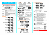
installed and configured. The Controller front panel indicators and keys are shown
in Figure 2-1.
2.2SELECTING THE PARAMETER TO BE
DISPLAYED/ADJUSTED
After the Controller has performed its power-up self-test, the initial displays
appear. The Scroll key may then be used to step through the available displays.
These displays are dependent upon whether the Controller has been configured
for Single Setpoint operation or Dual Setpoint operation (see overleaf).
O075-22-1
PM-0075
Figure 2-1Front Panel Indicators and Control Keys

NOTES
1. Setpoint is not adjustable if Setpoint Strategy = 1 (see Subsection 3.2.40)
but is adjustable if Setpoint Strategy = 2. Active setpoint is one of: Setpoint,
Setpoint 1, Setpoint 2 or Soft Start Setpoint, as appropriate.
2. Appears only if setpoint ramping is enabled and ramp rate is in the
range 1 - 9999.
3. Ramp rate is adjustable in the range 1 - 9999 (On) and Off (blank).
2-2O075-2
PM-0075

NOTES (continued)
4. Only appears if a Soft Start is in progress; see Subsection 2.4.
5. Appears only if an alarm is active; see Subsection 2.6.
6. In dual setpoint operation, the lower display distinguishes between the
active and inactive setpoints in the following manner:
2.3ADJUSTING THE DISPLAYED PARAMETER
If either of these keys is held down for 10 seconds or more, the adjustment rate
changes to “high speed” mode.
2.4SOFT START
Soft Start is used when a gentle start-up phase is required, before going to full
working temperature. During Soft Start, a dedicated setpoint is used to control the
process to a lower temperature than normal. A power limit can be applied to
Output 1 during Soft Start, constraining the average Output 1 power. During Soft
Start, the Output 1 cycle time is automatically reduced to give added protection
against thermal shock (NOTE: because of the nature of time-proportioned outputs,
Output 1 will still be fully-on for part of each output cycle).
O075-22-3
PM-0075

Soft Start Time, Soft Start Setpoint and power limit are all adjustable in Set Up Mode
(see Section 3). Soft Start is aborted at start-up if the process variable exceeds the
Soft Start Setpoint. Setpoint ramping is inhibited during Soft Start. During a Soft
Start, the Soft Start time remaining at any moment may be read from the front
panel.
2.5INDICATION OF AN ALARM GOING ACTIVE
If any of the Heater Break Alarms (High, Low or Short Circuit), Alarm 1 or Alarm 2
goes active, the HB/AL indicator will flash.
2.6ALARM STATUS DISPLAY
(available if one or more alarms are active)
The alarm status display is in the following format:
2.7OVER-RANGE/UNDER-RANGE DISPLAYS
If the process variable goes under-range or over-range, the upper display will
show the appropriate one of:
2 -4O075-2
PM-0075

2.8SENSOR BREAK INDICATION
If a break is detected in the sensor circuit, the upper display will show:
The reaction of the outputs and alarms to a detected sensor break is dependent
upon the input type.
2.9OUTPUT TURN OFF
(AM Key Usage Set Up parameter = )
Press the AM key to switch between automatic control and the control output(s)
being permanently turned off. A return to automatic control is via a bumpless
transfer. The SET indicator flashing pattern will be mostly OFF (if in Operator Mode)
or mostly ON (if in Set Up Mode).
2.10MANUAL CONTROL MODE
(AM Key Usage Set Up parameter = )
Press the AM key to switch between manual control and automatic control. In
manual control, the output power is displayed and may be adjusted. The SET
indicator flashing pattern will be mostly OFF (if in Operator Mode) or mostly ON (if
in Set Up Mode).
Transfer between automatic control and manual control is bumpless in both
directions.
2.11HEATER CURRENT DISPLAY
(AM Key Usage Set Up parameter = )
Press the AM key to display quickly the process variable/heater current,
regardless of the original display. The heater current display is in the format:
Press the AM key again to display the process variable/setpoint (i.e. the first
Operator Mode display). Subsequent AM key presses will switch between these
two displays.
O075-22-5
PM-0075

2.12SOFT START IN PROGRESS
If a Soft Start is in progress, the heater current display will show (in the lower
display):
The normal heater current display will be restored as soon as the Soft Start time
has expired.
2.13Q UICK TRANSFER OF HEATER CURRENT TO
NOMINAL VALUE
The nominal value of the heater current is manually adjustable in Set Up Mode.
However, to set the nominal value to the prevailing heater current value in
Operator Mode:
2-6O075-2
PM-0075

2.14PRE-TUNE
To tune approximately the Controller’s PID parameters, activate Pre-Tune:
The AT indicator will flash whilst Pre-Tune is operating. To dis-engage Pre-Tune,
repeat this procedure (the AT indicator will go OFF).
2.15SELF-TUNE
To optimise tuning whilst the Controller is operating, activate Self-Tune:
To dis-engage Self-Tune, repeat this procedure (the AT indicator will go OFF).
O075-22-7
PM-0075

2.16TO VIEW THE HARDWARE DEFINITION CODE
The Hardware Definition Code indicates the input type and output type(s) fitted
(see below). To view this Code:
The same key action causes a return to the normal Operator Mode display. An
automatic return is made to the normal Operator Mode display after 30 seconds.
The Hardware Definition Code has the following significance:
2-8O075-2
PM-0075
Value0 1 2 3 4 5 7 8 9
Input
RTD
InputThermo-
couple
Input
Output
1
Relay
Output SSR
Drive
Output
Solid
State
Output
Output
2( & 4)
Not
fittedRelay
Output
2
SSR
Drive
Output
2
Solid
State
Output
2
Relay
Output
2 & 4 *
Output
3
Not
fittedRelay
Output DC
0-10V
Output
DC
0-20mA
Output
DC
0-5V
Output
DC
4-20mA
Output
Solid
State
Output
* Dual Relay Option PCB must be fitted

3SET UP MODE
3.1 ENTRY INTO SET UP MODE
NOTE: If the upper display shows:
(i.e. all decimal point positions ON), parameters are at their default values,
possibly due to a change in Controller configuration. To cancel this
indication, adjust any Set Up Mode parameter (see below). It is
recommended that all configuration parameters are finalised before any
adjustments are made to Set Up Mode parameters.
O075-33-1
PM-0075

3.2SET UP MODE PARAMETERS
3-2O075-3
PM-0075
ParameterLegend Adjustment RangeDefault
Input Filter Time
Constant OFF, 0.5s to 100.0s In 0.5s
increments2.0s
Process Variable Offset ±input span of Controller0
Output Power0 to 100%Read Only
Output Power 2
40 to 100%Read Only
Proportional Band 10.0% to 999.9% of input span10.0%
Proportional Band 2
14,0.0% to 999.9% of input span10.0%
Reset (Integral Time
Constant) 11s to 99m 59s and OFF.5m 00s
Rate (Derivative Time
Constant) 100s to 99m 59s1m 15s
Overlap/Deadband 14,−20% to + 20% of Proportional
Band 1 + Proportional Band 2
0%
Manual Reset (Bias)
10% to 100% (single output)
−100% to +100% (dual output)
25%
ON/OFF Differential 2
:
Output 1 only
Output 2 only
4
Outputs 1 & 2
4
0.1% to 10% of input span 0.5%
Setpoint High LimitSetpoint to Range Max.Range
Max.
Setpoint Low Limit Range Min. To SetpointRange
Min.
Table 3-1Set Up Parameters

O075-33-3
PM-0075
ParameterLegend Adjustment RangeDefault
Recorder Output
Scale Max.−1999 to 9999Range Max.
Recorder Output
Scale Min.-1999 to 9999Range Min.
Output 1 Power Limit
10 to 100% of full power100%
Output 1 Cycle Time 0.5, 1, 2, 4, 8, 16, 32, 64, 128,
256 or 512 seconds32seconds
Output 2 Cycle Time 0.5, 1, 2, 4, 8, 16, 32, 64, 128,
256 or 512 seconds32seconds
Process High Alarm 1
value 3Range Min. To Range Max. Range Max.
Process Low Alarm 1
value 3Range Min. To Range Max. Range Min.
Band Alarm 1 value
30 to span from Setpoint5 units
Deviation Alarm 1
value 3±span from Setpoint5 units
Alarm 1 Hysteresis1 - 250 units1 unit
Process High Alarm 2
value 3Range Min. To Range Max. Range Max.
Process Low Alarm 2
value 3Range Min. To Range Max. Range Min.
Band Alarm 2 value
30 to span from Setpoint5 units
Deviation Alarm 2
value 3±span from Setpoint5 units
Alarm 2 Hysteresis1 - 250 units1 unit
Heater Current High
ScaleLimit 10.0A to 20.0A in 0.1A steps
21A to 100A in 1A steps50A
Heater Current
Nominal
90 to Heater Current High
Scale Limit High Scale
Limit
Low Heater Break
Alarm level (% or
amount below
nominal heater
current)
1% to 100% (of nominal) and
0 (OFF) or 0.1A/1A to Heater
Current High Scale Limit
20% or 0 (OFF)
Table 3-1 (Cont.)Set Up Parameters

3-4O075-3
PM-0075
ParameterLegend Adjustment RangeDefault
High Heater Break
Alarm level (% or
amount above
nominal heater
current)
1% to 100% (of nominal) and 0
(OFF) or 0.1A/1A to Heater
Current High Scale Limit
0 (OFF)
Short Circuit Heater
Break Alarm 100 (disabled) or 1 (enabled) 1 (enabled)
Soft Start Setpoint Range Min. To Range Max. Range Min.
Soft Start Time 15s to 59m 45s and 0 (OFF) in
15-second increments0 (OFF)
Auto Pre-Tune
Enable/Disable0 (disabled) or 1 (enabled) 0 (disabled)
AM Key Usage Output Turn-off
Manual Control
Heater Current
display/Manual
Control Disable
SP Ramping
Enable/Disable0 (disabled) or 1 (enabled) 0 (disabled)
Comms. Write
Enable/Disable 60 (disabled) or 1 (enabled) 1 (enabled)
Setpoint Strategy 1 or 21
Lock Value0 to 9999 10
OPERATOR MODE DISPLAYS (still accessible in Set Up Mode)
PV/Active SPSee Subsection 2.2 -
PV/Heater Current Read Only-
SP or SP1 8SPHi to SPLo SPLo
SP2 (Dual SP only)SPHi to SPLoSPLo
Ramping SP value 5Read Only -
SP Ramp Rate
71 to 9999 and OFF OFF
Soft Start Time
RemainingRead Only-
Alarm Status Read Only (see Subsection 2.6)-
Table 3-1 (Cont.) Set Up Parameters
/