Legrand CD-250 Multi-Way Dimming Wall Switch Vacancy Sensor Installation guide

Category
Motorcycle Accessories
Type
Installation guide

This manual is also suitable for

Wattstopper
®
Multi-Way Dimming Wall Switch Vacancy Sensor
Installation Instructions • Instructions d’Installation • Instrucciones de Instalación
No: 24210 – 09/16 rev. 1
Catalog Number • Numéro de Catalogue • Número de Catálogo: CD-250
Country of Origin: Made in China • Pays d’origine: Fabriqué en Chine • País de origen: Hecho en China
DESCRIPTION AND OPERATION
The CD-250 Multi-Way Dimming Wall Switch Vacancy Sensor is designed to replace a
standard single pole or multi-way (3-way, 4-way) switch or dimmer. It is ideal for any indoor
area where occupancy sensor-based manual ON/OFF and Dimming control is desirable.
Like a standard switch, you press the ON/OFF/DIM button to turn the dimmable lighting load
ON and OFF. Unlike a standard switch, the CD-250 automatically turns OFF the controlled
load after the coverage area has been vacant for a period of time (Time Delay). If motion is
detected within 30 seconds after it automatically turns OFF, the CD-250 automatically turns
the load back ON. Like a standard dimmer, once the lighting load is ON, you can dim it UP or
DOWN by pushing and holding the ON/OFF/DIM button. When you push the ON/OFF/DIM
button to turn the dimmable load ON, the CD-250 recalls the last used dimming level.
The CD-250 can be wired with up to 3 additional CD-250s for multi-way Manual-ON/OFF,
Auto-OFF of one or several loads (up to one load connected to each CD-250). It can also be
wired to up to 4 RH-253 single pole momentary wall switches for multi-way Manual-ON/OFF
Automatic-OFF control of one load.
Lighted Switch
To help you locate the CD-250 in a dark room, the amber LED illuminates the ON/OFF/DIM
button while the controlled load is OFF. When the controlled load is ON, the LED is OFF.
The lighted switch ON/OFF/DIM button can be used to manually turn ON and OFF the lighting
load and to dim it UP and DOWN.
To turn the load ON, tap firmly on the ON/OFF/DIM button once. The amber LED turns OFF and the load turns ON to the last used
dimming level. The lighting load may or may not appear to be ON depending on how low the lights were set the last time they were
dimmed.
Once the load has been turned ON, push and hold the ON/OFF/DIM button to dim the lights UP or DOWN. To reverse the dimming
direction momentarily release the ON/OFF/DIM button, then push and hold it again. This feature will allow you to reach the desired
dimming level quicker.
Time Delay
The time delay can be selected by the user during set up. It can be adjusted to any of these fixed values:15 seconds/5 minutes/15
minutes/30 minutes. It is recommended to set all of the sensors related to the same load to the same time delay to ease understanding
of the multi-way control operation as well as trouble shooting. For additional information on how to adjust it, please read the SENSOR
ADJUSTMENT section of this installation manual.
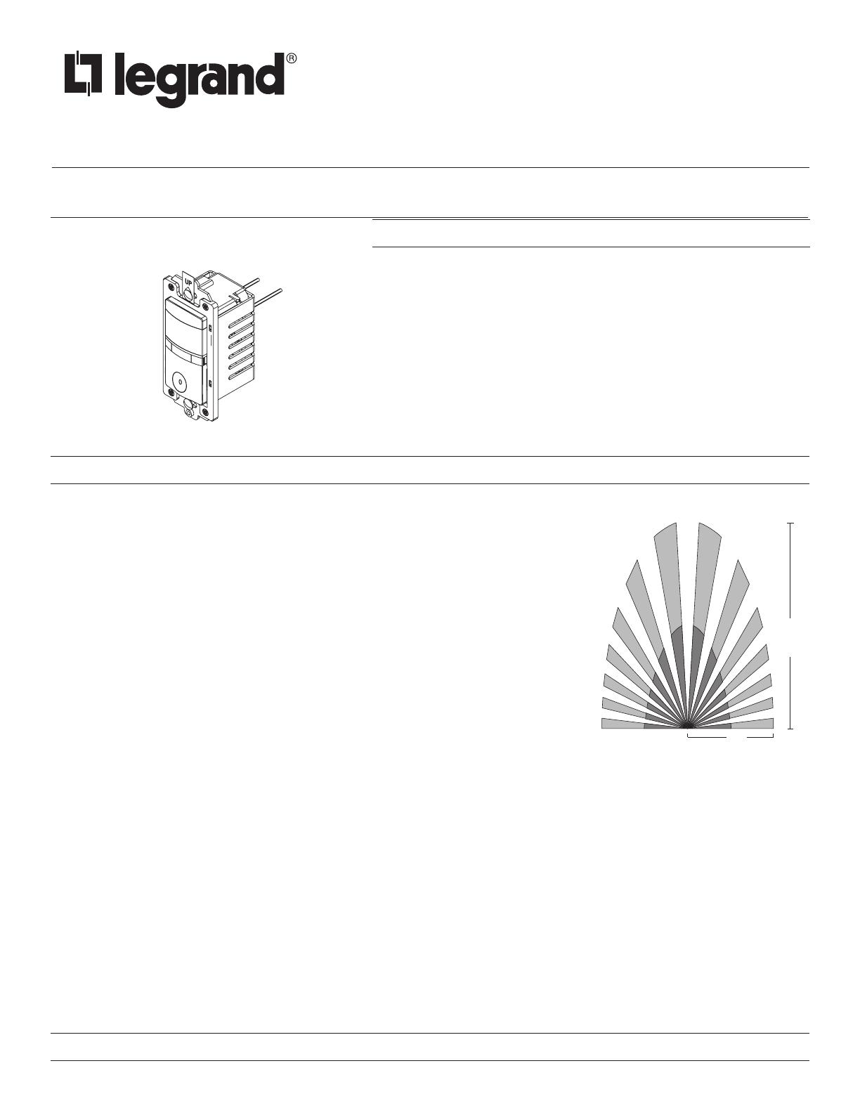
Coverage Area
The CD-250 has a maximum range of 180 degrees and a coverage area of 600 sq. feet (56 sq. meters). The sensor must have a clear
and unobstructed view of the coverage area. Objects blocking the sensor’s lens may prevent detection thereby causing the light to turn
OFF even though someone is in the area.
WINDOWS, GLASS DOORS, AND OTHER TRANSPARENT BARRIERS WILL OBSTRUCT THE SENSOR’S VIEW AND PREVENT DETECTION.
SPECIFICATIONS
Voltage ................................................................................................ 120VAC,60Hz
Load (Multi-Way) .................................................................................... 25-500 Watt
Compatability ........................................................................................ Incandescent
Time Delay Adjustment .....................................................15 seconds to 30 minutes
Environment ...................................................................................... Indoor use only
Operating Temperature ......................................................32° to 104°F (0° to 40°C)
Humidity ............................................................................95% RH, non-condensing
Electrical Supply Wire Requirement
Minimum temperature rating .................................................................75°C (167°F)
Tools Needed ..................................................Insulated Screwdriver, Wire Strippers

P

P
Fig. 1: Sensor Coverage Area
2
INSTALLATION & WIRING
These instructions describe single pole, 3-way and multi-way circuit applications.
If you are unable to clearly identify some or all of the wires identified in step 2 of the instructions, you should consult with a qualified
electrician.
Steps 4a, 4b, and 4c describe each circuit application.
For information about other applications, consult technical support or the Wattstopper website.
1. Prepare the switch box.
After the power is turned OFF at the circuit breaker box, remove the existing wall plate and mounting screws. Pull the old switch
out from the wall box.
2. Identify the type of circuit.
You may connect the CD-250 to a single pole (see Fig. 2) or 3-way circuit (see Fig. 2a).
In a 3-way circuit, two traveler wires connect to both switches. Another wire provides power from the circuit box to one of the
switches. A wire connects from one switch to the load. A ground wire may also be connected to a ground terminal on the old
switches. A neutral wire should also be present in both wall boxes
3. Prepare the Wires.
Tag the wires currently connected to the existing switch so that they can be identified later. Disconnect the wires. Make sure the
insulation is stripped off of the wires to expose their copper cores to the length indicated by the “Strip Gauge,” in Fig. 3. (approx.
1/2 inch).
FOR YOUR SAFETY: CONNECTING A PROPER GROUND TO THE SENSOR PROVIDES PROTECTION AGAINST ELECTRICAL SHOCK IN
THE EVENT OF CERTAIN FAULT CONDITIONS. IF A PROPER GROUND IS NOT AVAILABLE, CONSULT WITH A QUALIFIED ELECTRICIAN
BEFORECONTINUING INSTALLATION.
CAUTION — WARNING
TO REDUCE THE RISK OF OVERHEATING AND POSSIBLE DAMAGE TO OTHER EQUIPMENT, DO NOT INSTALL TO CONTROL A
RECEPTACLE, A MOTOR-OPERATED APPLIANCE, A FLUORESCENT LIGHTING FIXTURE, OR A TRANSFORMER-SUPPLIED APPLIANCE.
DISCONNECT POWER TO THE WALL SWITCH BOX BY TURNING OFF THE CIRCUIT BREAKER OR REMOVING THE FUSE
FOR THE CIRCUIT BEFORE INSTALLING THE CD-250, REPLACING LAMPS, OR DOING ANY ELECTRICAL WORK.
Strip Gauge
1/2"
12.7 mm
Fig. 3: Wire Stripping
NEUTRAL
GROUND
LOAD/Common
(power to lamp)
NEUTRAL
GROUND
HOT/Common
(power from ci rcuit box)
TRAVELER
TRAVELER
Lamp/load
MASTER SWITCH
AUXILIARY SWITC
H
Fig. 2a: Typical 3-way Switch Wiring
Ground
HOT (power from
circuit box)
LOAD
(power
to lamp)
NEUTRAL
Fig. 2: Typical Single Pole Switch
INITIAL POWER-UP DELAY & CALIBRATION
There is an initial one minute warm-up and calibration period the first time power is applied to the unit, after a power failure lasting more
than 5 minutes and after the dimming load is replaced.
Load Calibration: The CD-250 calibrates its dimming range to the load’s wattage rating by briefly dimming the load up and down from its
minimum output (approx. 10%) to its maximum.
3
4. Circuit Applications
a. Single pole wiring:
Twist the existing wires together with the wire leads on the CD-250 sensor as indicated below. Cap them securely using the wire
nuts provided (See Fig 4a).
Connect the green or non-insulated (copper) GROUND wire from the circuit to the green wire on the CD-250.
Connect the NEUTRAL wire from the circuit and from the lamp (LOAD) to the white wire on the CD-250.
Connect the power wire from the circuit box (HOT) to the black wire on the CD-250.
Connect the power wire to the lamp (LOAD) to the red wire on the CD-250.
Cap the yellow wire on the CD-250. It is not used in single pole applications.
b. 3-way wiring using two CD-250s:
Twist the existing wires together with the wire leads on the CD-250 sensors as indicated below. Cap them securely using wire
nuts provided. (See Fig. 4b)
Connect the green or non-insulated (copper) GROUND wire from the circuit to the green wire on the CD-250.
Connect the NEUTRAL wire from the circuit and from the lamp (LOAD) to the white wire on the master CD-250.
The term “master” designates the CD-250 that connects to the load.
Connect the NEUTRAL wire from the circuit in the other wiring box to the white wire on the auxiliary CD-250.
Connect the power wire from the circuit box (HOT) to the black wire on the auxiliary CD-250 and to the TRAVELER 1 wire.
Connect the TRAVELER 1 wire from the black wire of the auxiliary CD-250 to the black wire of the master CD-250.
Connect the lamp power (LOAD) to the red wire on the master CD-250.
Cap the red wire on the auxiliary CD-250.
Connect the TRAVELER 2 wire coming from the yellow wire of another CD-250 to the yellow wire of the CD-250 that you are
wiring.
AUXILIARY CD-250
MASTER CD-250
Red
Ground
Yellow
Black
White
Red
Ground
Yellow
Black
White
Load
Traveler 1
Traveler 2
Neutral
Hot
120V/60Hz
Neutral
Fig. 4b: Wiring Diagram, 3-Way Using Two DC-250s
Green
GROUND
Black
HOT (power
from circuit box)
White
NEUTRAL
Red
LOAD (power
to dimmable lamp)
Yellow
CAP (Traveler,
not used for
single pole)
Industry standard
switch cover plate
(not provided)
Fig. 4a: Sensor orientation, single pole wire connections and wall box assembly
4
Red
Ground
Yellow
Black
White
Load
Traveler 2
Hot
120V/60Hz
Neutral
Traveler 1 (Hot)
RH-253
Ground
RH-253
Ground Ground
Traveler 2
Traveler 1
Traveler 2
Traveler 1
Traveler 2
Traveler 1
Fig. 4c: Multi-Way Wiring Using One CD-250 and three RH-253s
c. Multi-way wiring using one CD-250 and up to four RH-253s:
One CD-250 can be connected with up to 4 RH-253 single pole momentary wall switches for multi-way Manual-ON/OFF control
of one single load. The CD-250 must be installed in the wiring wall box that connects to the load.
Connect the existing wires to the wire leads on the CD-250 sensor as indicated below (See Fig. 4c). Cap them securely using
wire nuts provided.
Connect the green or non-insulated (copper) GROUND wire from the circuit to the green wire on the CD-250.
Connect the NEUTRAL wire from the circuit and from the lamp (LOAD) to the white wire on the CD-250.
Connect the power wire from the circuit box (HOT) to one terminal on each RH-253 single pole momentary wall switch and to
the TRAVELER 1 wire.
Connect the TRAVELER 1 wire coming from each RH-253 wiring box to the black wire of the CD-250.
Connect the lamp power (LOAD) to the red wire on the CD-250.
Connect the TRAVELER 2 wire to the other side of each RH-253 single pole momentary wall switch and to the yellow wire of the
CD-250.
5. Put the CD-250s (and RH-253s if applicable) into their respective wall boxes.
Position them with the lens positioned above the ON/OFF/DIM button (lens at top, ON/OFF/DIM button at bottom). Secure to the
wall box with the screws provided.
6. Make any necessary adjustments.
See the SENSOR ADJUSTMENT section for information.
7. Install cover plate.
Install industry standard decorator wall switch cover plate (not included).
8. Restore power to the circuit.
Turn on the breaker or replace the fuse.
5
SENSOR ADJUSTMENT
To adjust the CD-250, you use a control located under the ON/OFF/DIM button. The wall switch
cover plate must be removed to gain access to the time adjustment dial under the ON/OFF/DIM
button.
For multi-way operation, the Time Delay should be the same in all sensors related to the
same load.
1. Firmly grasp the side edges of the Lock Bar and gently pull it away from the switch face
until it clicks. Do NOT attempt to pull the Lock Bar off of the switch!
2. Firmly grasp the side edges of the ON/OFF/DIM button. Slide the button downward
approximately 1/2 inch to expose the adjustment dials.
Adjusting the Time Delay
Turn the right dial counter-clockwise to reduce the amount of time the lights will remain on after
the last motion detection (minimum = 15 seconds). Turn the same dial clockwise to increase
this time delay (maximum = 30 minutes). You can only select the following values: 15 seconds/5
minutes/15 minutes/30 minutes.
Warning: Do not overturn the Time Delay adjustment dial!
TEST MODE
To test the detection coverage:
1. Press and hold the ON/OFF/DIM button. After 10 seconds the lighted switch turns off. The load turns ON if it was not already ON.
The sensor is now in a TEST mode that lasts 5 minutes. (You can end the TEST mode sooner by pressing the ON/OFF/DIM button
for another 10 seconds).
DURING THE TEST MODE, THE CONTROLLED LOAD TURNS ON FOR 5 SECONDS EACH TIME THE SENSOR
THAT INITIATED THE TEST MODE DETECTS OCCUPANCY.
2. Move out of the coverage area or stand very still. The controlled load turns OFF after 5 seconds if no motion is detected.
3. Move into the coverage area for the unit that initiated the TEST mode. The controlled load turns ON for 5 seconds each time
the sensor detects motion. After 5 seconds expire without motion detection, the load turns OFF. The controlled load turns ON
automatically with the next motion detection and stays ON for 5 seconds.
4. Repeat as necessary to ensure that the desired coverage areas are within detection range.
You can do this test for each CD-250 in your multi-way configuration. So that you can determine the actual coverage area for each
multi-way switch individually, only the CD-250 that is in TEST mode will control the load.
REPLACING LAMPS
When replacing a lamp connected to an CD-250, use the Air Gap Isolation feature for safety. If you have more than one CD-250
controlling one or various loads in a multi-way wiring configuration, apply the instructions below to all CD-250s for safety.
1. Push in the Air Gap Switch shown in Figure 5 so that it clicks and locks into a depressed position below the surface of the rest of
the CD-250. This engages the Air Gap, which stops electricity from flowing to the connected load.
2. After replacing the lamp(s), press the Air Gap Switch so that it returns to a position that is flush with the surface of the rest of the
CD-250. This allows the dimming sensor to control the lighting load correctly.
3. The CD-250 then calibrates its dimming range to the load’s wattage rating by briefly dimming the load up and down from its
minimum output (approx. 10%) to its maximum.
TROUBLESHOOTING
Check the position of the Air Gap Switch on all CD-250s before beginning troubleshooting.
Lighted switch is OFF, no load response to ON/OFF/DIM button(s) press or to any of the RH-253 momentary wall switches (if
applicable):
Make certain that the circuit breaker is on and functioning.
Lighted switch is ON, no load response to ON/OFF/DIM button(s) press or to any of the RH-253 momentary wall switches (if applicable):
Check the controlled dimmable lighting load(s). Make sure that the load(s) connected to the CD-250s is (are) between 25- 500
watts.
The lighting load (s) may not appear to be ON if the last used dimming level was very low. To verify if this is the case, firmly tap the
ON/OFF/DIM button one time. The amber LED should turn off. Next, press and hold the ON/OFF/DIM button to turn UP the lighting
level. If the lights do not get brighter, call technical support.
Lock Bar
Time Delay
Adjustment
Dial
Slide down
On/Off/Dim
Button
Air Gap Switch
09560r1
Suggested time delays
Bath or Ded room: 30: min.
Half or Stairway: 5-15 min
30
Min.
Sec.
15
Min.
5
Min.
15
Fig. 5: Sensor Adjustment Controls
800.879.8585
www.legrand.us/wattstopper
No. 24210 – 09/16 rev. 1
© Copyright 2016 Legrand All Rights Reserved.
© Copyright 2016 Tous droits réservés Legrand.
© Copyright 2016 Legrand Todos los derechos reservados.
Wattstopper warranties its products to be free
of defects in materials and workmanship for a
period of five (5) years. There are no obligations
or liabilities on the part of Wattstopper for
consequential damages arising out of, or in
connection with, the use or performance of this
product or other indirect damages with respect
to loss of property, revenue or profit, or cost of
removal, installation or reinstallation.
Wattstopper garantit que ses produits sont
exempts de défauts de matériaux et de fabrication
pour une période de cinq (5) ans. Wattstopper
ne peut être tenu responsable de tout dommage
consécutif causé par ou lié à l’utilisation ou
à la performance de ce produit ou tout autre
dommage indirect lié à la perte de propriété, de
revenus, ou de profits, ou aux coûts d’enlèvement,
d’installation ou de réinstallation.
Wattstopper garantiza que sus productos
están libres de defectos en materiales y mano
de obra por un período de cinco (5) años. No
existen obligaciones ni responsabilidades por
parte de Wattstopper por daños consecuentes
que se deriven o estén relacionados con el
uso o el rendimiento de este producto u otros
daños indirectos con respecto a la pérdida
de propiedad, renta o ganancias, o al costo
de extracción, instalación o reinstalación.
WARRANTY INFORMATION INFORMATIONS RELATIVES À LA GARANTIE INFORMACIÓN DE LA GARANTÍA
Load will not turn OFF automatically:
Press the ON/OFF/DIM button. If the controlled load turns OFF, go to next step.
The time delay can be set from 15 seconds to 30 minutes. Check the time delay setting for each CD-250 in your multi-way
configuration. Ensure that all CD-250s have the same time delay setting. Ensure that there is no movement within any of the
sensors’ view for the set time period. Hot air currents and heat radiant devices can cause false detection. Make sure the sensor is
at least 6 feet (2 meters) away from devices that are a significant heat source (e.g., heater, heater vent, high wattage light bulb).
IF LOAD DOES NOT RESPOND PROPERLY AFTER FOLLOWING TROUBLESHOOTING, TURN OFF POWER TO THE CIRCUIT THEN CHECK
WIRE CONNECTIONS OR CALL TECHNICAL SUPPORT.
COVER PLATES
Wattstopper CD wall switches fit behind industry standard decorator style switch cover plates.
  • Page 1 1
  • Page 2 2
  • Page 3 3
  • Page 4 4
  • Page 5 5
  • Page 6 6

Legrand CD-250 Multi-Way Dimming Wall Switch Vacancy Sensor Installation guide

Category
Motorcycle Accessories
Type
Installation guide
This manual is also suitable for

Ask a question and I''ll find the answer in the document

Finding information in a document is now easier with AI