INSTRUCTIONS
IVELOT Edge-lit Area Light
RAB Lighting is committed to creating high-quality, aordable, well-designed and energy-ecient LED lighting and controls that make it easy for electricians to install
and end users to save energy
. W
e’
d love to hear your comments
.
Please call the Marketing Depar
tment at 888-RAB-1000 or email:
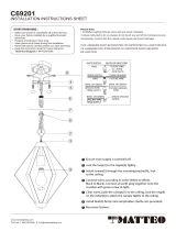
[email protected]Dimmable
Driver
LINE
NEUTRAL
NEUTRAL
GRAY (-)
VIOLET (+)
LOAD
Occupancy Sensor
5E4
800.879.8585
www.wattstopper.com
1r59151
DAOL
ENIL
TUEN
)telo
i
v
(
(g
rey)
18-20 AWG Solid CU Wire Only
230 VAC, 50 Hz
1200W max ballast
FSP-211
DNRG
-MID
DIM+
14-18 AWG Solid CU Wire Only
High/Low PIR
Ground
LED
1.
2.
1.
2.
3.
4.
•
CAUTION: Be sure fixture temperature is cool enough to touch.
Do not clean or maintain while fixture is energized.
1.
2.
Universal voltage driver and Wattstopper Sensor permits
operation at 120-277V, 50 or 60 Hz. For 0-10V Dimming with
Wattstopper, follow the wiring directions in Fig.9.
1.
2.
3.
4.
Do NOT connect the GROUND of the
dimming fixture to the output
5.
6.
7. Do NOT connect