SignaMax Managed Layer 2 Industrial Switch User guide
- Category
- Network switches
- Type
- User guide
This manual is also suitable for

SIGNAMAX 065-7912HTB
Industrial Ethernet Switch
User Manual
Dec 14, 2012
Version: V 1.3

SIGNAMAX 065-7912 HTB Industrial Ethernet Switch
i
Table of Contents
1 PREFACE .................................................................................................................................... 1-1
1.1 CONVENTIONS .............................................................................................................................. 1-1
1.2 DEVICE INTRODUCTION ................................................................................................................ 1-1
1.2.1 Brief Introduction ............................................................................................................. 1-1
1.2.2 Port Introduction .............................................................................................................. 1-2
1.2.3 Indicator Introduction ..................................................................................................... 1-2
1.2.4 Default Configuration ...................................................................................................... 1-2
1.2.5 Login to the Switch .......................................................................................................... 1-3
1.2.6 WEB Management Overview ......................................................................................... 1-4
2 SYSTEM INFORMATION ........................................................................................................... 2-1
3 ADVANCED CONFIGURATION ................................................................................................ 3-1
4 PORT MANAGEMENT ............................................................................................................... 4-1
4.1 PORT CONFIGURATION ................................................................................................................. 4-1
4.2 PORT AGGREGATION .................................................................................................................... 4-2
4.2.1 Aggregate Groups ........................................................................................................... 4-2
4.2.2 LACP Port Setting ............................................................................................................ 4-3
4.2.3 Aggregate Basic Setting ................................................................................................ 4-3
4.2.4 LACP Status Setting ........................................................................................................ 4-4
4.3 PORT BANDWIDTH ........................................................................................................................ 4-4
4.4 PORT MIRRORING ......................................................................................................................... 4-5
5 VLAN ............................................................................................................................................ 5-1
5.1 ADVANCED .................................................................................................................................... 5-1
5.2 PORT-BASED VLAN ..................................................................................................................... 5-1
5.3 802.1Q VLAN ............................................................................................................................. 5-2
5.3.1 802.1Q VLAN Setting ....................................................................................................... 5-3
5.3.2 802.1Q Configuration ...................................................................................................... 5-4
5.3.3 802.1Q Port ........................................................................................................................ 5-4
5.4 GARP SETTING ........................................................................................................................... 5-5
5.4.1 GARP ................................................................................................................................... 5-5
5.4.2 GVRP ................................................................................................................................... 5-6
6 QOS .............................................................................................................................................. 6-1
6.1 QOS CONFIGURATION .................................................................................................................. 6-1
6.1.1 General Priority ................................................................................................................ 6-1
6.1.2 Port QoS Configuration .................................................................................................. 6-1
6.2 SCHEDULING MECHANISM ........................................................................................................... 6-2
6.3 TRANSMIT QUEUES ...................................................................................................................... 6-2
6.4 DSCP MAP .................................................................................................................................. 6-3
7 FORWARDING ............................................................................................................................ 7-1
7.1 UNICAST MAC ADDRESS ............................................................................................................. 7-1
7.1.1 MAC Address .................................................................................................................... 7-1
7.1.2 Dynamic Unicast MAC .................................................................................................... 7-2
7.2 MULTICAST MAC ADDRESS ........................................................................................................ 7-2
7.3 IGMP SNOOPING CONFIGURATION ............................................................................................. 7-4
7.3.1 IGMP Snooping ................................................................................................................. 7-5
7.3.2 Route Port .......................................................................................................................... 7-5

SIGNAMAX 065-7912 HTB Industrial Ethernet Switch
ii
7.3.3 Misc ..................................................................................................................................... 7-6
8 SECURITY ................................................................................................................................... 8-1
8.1 MANAGEMENT SECURITY ............................................................................................................. 8-1
8.2 PORT AUTHENTICATION ............................................................................................................... 8-2
8.2.1 802.1x Port ......................................................................................................................... 8-3
8.2.2 802.1x Misc ........................................................................................................................ 8-4
8.3 MAC AUTHENTICATION ................................................................................................................ 8-5
8.3.1 Port Configuration ........................................................................................................... 8-5
8.3.2 Misc ..................................................................................................................................... 8-6
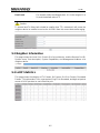
8.3.3 Authentication Information ............................................................................................ 8-6
8.4 STORM CONTROL ......................................................................................................................... 8-6
9 LLDP ............................................................................................................................................ 9-1
9.1 MANAGEMENT LLDP ................................................................................................................... 9-1
9.1.1 Configuration .................................................................................................................... 9-1
9.1.2 TLVs ..................................................................................................................................... 9-4
9.1.3 LLDP Parameters ............................................................................................................. 9-4
9.2 NEIGHBOR INFORMATION ............................................................................................................. 9-5
9.3 LLDP STATISTICS ........................................................................................................................ 9-5
10 STATISTICS ............................................................................................................................. 10-1
10.1 PORT STATUS ........................................................................................................................... 10-1
10.2 PORT STATISTICS ..................................................................................................................... 10-1
10.3 VLAN LIST ............................................................................................................................... 10-2
10.4 MAC ADDRESS TABLE ............................................................................................................ 10-2
10.4.1 Unicast MAC Address ................................................................................................. 10-2
10.4.2 Multicast MAC Address .............................................................................................. 10-2
10.5 IGMP SNOOPING GROUP ........................................................................................................ 10-2
10.6 LINK AGGREGATION ................................................................................................................. 10-2
10.6.1 Manual Trunking Group ............................................................................................. 10-2
10.6.2 Static Trunking Group ................................................................................................ 10-3
10.6.3 LACP Trunking Group ................................................................................................ 10-3
10.7 RECOVERRING II™ STATUS .................................................................................................... 10-3
11 SPANNING TREE.................................................................................................................... 11-1
11.1 STP .......................................................................................................................................... 11-3
11.1.1 Basic STP ....................................................................................................................... 11-3
11.1.2 STP Information ............................................................................................................ 11-4
11.1.3 STP Port Attributes ...................................................................................................... 11-4
11.2 RSTP ....................................................................................................................................... 11-5
12 RECOVERRING II™ CONFIGURATION .............................................................................. 12-1
12.1 RECOVERRING II™ .................................................................................................................. 12-2
12.2 RECOVERRING II™ COUPLING ................................................................................................ 12-3
12.3 RECOVERRING II™ TIMER ....................................................................................................... 12-4
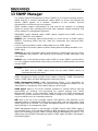
13 SNMP MANAGER ................................................................................................................... 13-1
13.1 SNMP ACCOUNT ..................................................................................................................... 13-2
13.1.1 SNMP Community ........................................................................................................ 13-2
13.1.2 SNMP User ..................................................................................................................... 13-2
13.2 SNMP TRAP ............................................................................................................................ 13-3
13.2.1 Global Trap .................................................................................................................... 13-3
13.2.2 Trap Host IP ................................................................................................................... 13-3
13.2.3 Trap Port ........................................................................................................................ 13-3
14 RMON ....................................................................................................................................... 14-1

SIGNAMAX 065-7912 HTB Industrial Ethernet Switch
iii
14.1 STATISTICS ............................................................................................................................... 14-1
14.2 HISTORY ................................................................................................................................... 14-3
14.2.1 History control .............................................................................................................. 14-3
14.2.2 History List .................................................................................................................... 14-3
14.3 ALARM ...................................................................................................................................... 14-4
14.4 EVENT CONFIGURATION ........................................................................................................... 14-6
14.4.1 Event ............................................................................................................................... 14-6
14.4.2 Event Log ....................................................................................................................... 14-7
15 ADMINISTRATION .................................................................................................................. 15-1
15.1 LANGUAGE ............................................................................................................................... 15-1
15.2 IP CONFIGURATION .................................................................................................................. 15-1
15.3 SNTP ....................................................................................................................................... 15-1
15.4 SMTP ....................................................................................................................................... 15-2
15.5 E-MAIL ALARM ......................................................................................................................... 15-2
15.5.1 System Event ................................................................................................................ 15-2
15.5.2 Port Event ...................................................................................................................... 15-3
15.6 RELAY ALARM .......................................................................................................................... 15-4
15.6.1 System Event ................................................................................................................ 15-4
15.6.2 Port Event ...................................................................................................................... 15-4
15.7 SYSTEM LOG ............................................................................................................................ 15-5
15.8 PING DIAGNOSIS ...................................................................................................................... 15-5
15.9 ACCOUNT ................................................................................................................................. 15-6
15.10 TFTP SERVICES .................................................................................................................... 15-6
15.10.1 Update Firmware ........................................................................................................ 15-7
15.10.2 Backup Configuration .............................................................................................. 15-7
15.10.3 Restore Configuration .............................................................................................. 15-7
15.11 REBOOT .................................................................................................................................. 15-8
15.12 RESET .................................................................................................................................... 15-8
15.13 SAVE CONFIGURATION ........................................................................................................... 15-8
16 LOGOUT .................................................................................................................................. 16-1
APPENDIX B SUPPORTED MIBS ............................................................................................... A-1

SIGNAMAX 065-7912 HTB Industrial Ethernet Switch
iv
Revision History
Date Version Description
Sep 10, 2012 V 1.0 Initial release
Oct 9, 2012 V 1.1 Added photo, face panel and indicator introduction
Dec 7, 2012 V 1.2
Added MDI/MDIX item in Port Configuration
Added Multicast MAC Address List
Added Appendix Ordering Information
Added Appendix Compatible SFP Modules
Dec 14, 2012 V 1.3
Added Appendix Supported MIBs

1 Preface
1-1
1 Preface
This manual applies to industrial switches SIGNAMAX 065-7912HTB.
1.1 Conventions
1.2 Device Introduction
1.2.1 Brief Introduction
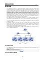
SIGNAMAX Series Industrial Ethernet Switches are designed to meet various
industrial application needs and provide customer with a high-end industrial Ethernet
network communication solution. SIGNAMAX series’ high availability and reliability, as
well as the rich security features, make it ideal for data transmission securely.
SIGNAMAX series provides powerful management capabilities, and can be managed
through Web, CLI, Telnet/serial console, Windows utility and SNMP. It is designed to
apply dual power supplies for redundancy with wide DC input range and support DIN
rail and wall mounting for installation in industrial environments.
“RecoverRing II™” is designed especially for industrial applications, providing fast
Ethernet ring protection and recovery within 20ms. From the management interface,
users can choose either port from normal Ethernet port or trunk port to form an
Ethernet ring for faster recovering and wider bandwidth to keeping industrial
applications running continuously.
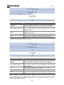
GUI Convention Description
Boldface Keywords on web management page are in Boldface
Italic Tab page names are in italic
<> Buttons are in <>
[ ] Menus and submenus are in [ ].
Note
This icon is added to the notes.
Caution
Means reader be careful. Improper operation may cause data
loss or damage to equipment.

1 Preface
1-2
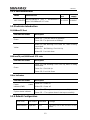
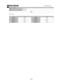
1.2.2 Port Introduction
Model Ethernet Port
Console
port
Power
supply
065-7912HTB
4X10/100BaseTX port + 4X100BaseFX
port+ 2X1000BaseX SFP slots
1X RS232 2X24VDC
1.2.3 Indicator Introduction
10/100BaseTX Port
Port Indicator Status Description
Green
Green On —The port works at 100Mbps.
Green Off—The port works at 10Mbps.
Yellow
Yellow On and Blinking—Port LINK UP, data is being
transmitted.
Yellow On – No Blinking –Port Link Up
Yellow Off - Port Link down
100BaseFX port/1000BaseX SFP slots
Port Indicator Status Description
Green
Green On and Blinking—Port Link Up, date is being
transmitted.
Green On—Port Link Up
Green Off—Port Link Down
Other Indicators
Port Indicator Status Description
Power status
indicator(PWR)
Green On—Power on
Yellow Off—Power off
System status indicator
Green On—The system starts up successfully
Green Off — The system doesn’t start up successfully.
1.2.4 Default Configuration
User Level User Name Password Privilege
Administrator superuser 123
Can carry out all the functions of the
switch.

1 Preface
1-3
User manager 123
Can carry out all the functions except:
• Create or delete an account
• Reset to default configuration
• Use the TFTP service to update
firmware, backup and restore
configuration.
Visitor guest (none)
Can use the internet diagnosis
commands, such as ping command
for system maintainace, and the
“show” commands except “show
user”, “show snmp community”,
“show snmp traps-
host” and “show
snmp user”.
Note: Visitor can only access the
switch by Console port.
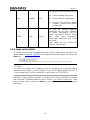
1.2.5 Login to the Switch
To access the switch web management function, open a web-browser and type in the
default address http://192.168.0.253
in the address field of the browser, then press the
Enter key.
Note:
To log in to the switch, the IP address of your PC should be set in the same subnet
addresses of the switch. For the first time, set your PC IP address as 192.168.0.x ("x"
is any number from 1 to 254, except 253), subnet mask as 255.255.255.0.
And then a login window will appear, as shown follows. Enter the default User Name
and Password. The default values are set in section 1.2.5 Default Configuration.
Then
click the Login button or press the Enter key, so that you can see the switch system
information.

1 Preface
1-4
If you need to change the switch IP address at the first time, you can modify it through
RS232 console, or using telnet to login, you can refer to “SIGNAMAX Entry-level
Series Industrial Switch CLI Manual V1.1”.
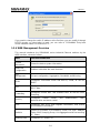
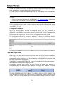
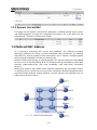
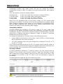
1.2.6 WEB Management Overview
This manual introduces the SIGNAMAX series industrial Ethernet switches by the
WEB interface, shown as follows.
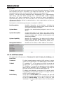
Menu Function Introduction
System
Information
Shows the device system information.
Advanced
Configuration
Enables or disables the main functions.
Port
Management
Set port configuration, Aggregation, Bandwidth and Mirroring
VLAN
Configures Port-
based VLAN and 802.1Q VLAN, as well as
GARP.
QoS
Configures QoS, Scheduling Mechanism, Transmit Queues and
DSCP Map.
Forwarding
Configures unicast MAC and multicast MAC as well as IGMP
Snooping.
Security
Configures Radius server, port authentication, MAC
authentication and storm control.
LLDP
Configures port LLDP and neighbor information
, and checks
LLDP statistics information.
Statistics
Checks Port Status, Port Statistics, VLAN List, MAC Address
Table, IGMP Snooping Group, Link Aggregation and RecoverRing
II™ Status
Spanning Tree Configures STP and RSTP.

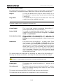
1 Preface
1-5
RecoverRing II™
Configuration
Configures RecoverRing II™, coupling and the related timers.
SNMP Manager Configures SNMP accouts and traps.
RMON
Configures RMON event, alarm and history and checks RMON
statistics.
Administration
Configures d
evice web interface language, IP, SNTP, SMTP.
Email alarm, relay alarm; checks system log; carries
out ping
diagnosis; manages accounts; uses TFTP services; reboots and
resets the device and saves the configuration.
Logout Logs out from the switch Web interface.

2 System Information
2-1
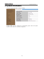
2 System Information
The device system information is shown as follows.
Through SNMP, you can configure the corresponding system name and system
location for each switch for convenient management.

3 Advanced Configuration
3-1
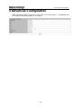
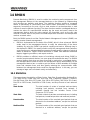
3 Advanced Configuration
IGMP Snooping, GVRP, STP, LACP, LLDP, 802.1X, RecoverRing II™ and Modbus can
be enabled or disabled globally on this page.

4 Port Management
4-1
4 Port Management
You can set port configuration, aggregation, bandwidth and mirroring with this menu.
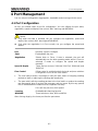
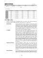
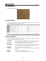
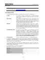
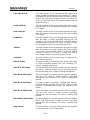
4.1 Port Configuration
At first, you should select a port for configuration. You can cofigure the port state,
negotiation, speed and duplex, flow control, MAC learning and MDI/MDIX.
Caution:
Only when the state is enbaled, can you configure the negotiation, speed and
duplex, flow control, MAC learning and MDI/MDIX.
Only when the negotiation is in Force mode, can you configure the speed and
duplex.
Port Specifies a port to configure
State Enable/disble the port
Negotiation Selects Auto or Force, if Auto is selected, the port will
automatically use the best operating mode; while is Force is
selected, it needs to configure the speed and duplex
manually.
Speed & Duplex There are four choices: 10M Half, 10M Full, 100M Half, and
100M Full.
Flow Control If flow control is enabled on both the local and peer switches.
If congestion occurs on the local switch:
• The local switch sends a message to notify the peer switch of stopping sending
packets to itself or reducing the sending rate temporarily.
• The peer switch will stop sending packets to the local switch or reduce the sending
rate temporarily when it receives the message; and vice versa. By this way, packet
loss is avoided and the network service operates normally.
If it is off, the port runs at full speed.
Learning Enable/disable learning function
MDI/MDIX Three selections: Auto, MDI and MDIX.
After clicking <Apply>, the lower part lists the port status.

4 Port Management
4-2
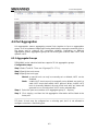
4.2 Port Aggregation
Link aggregation means aggregating several links together to form an aggregation
group, so as to implement outgoing/incoming load balance among the member ports in
the group and to enhance the connection reliability. Depending on different
aggregation modes, aggregation groups fall into three types: manual, static LACP, and
dynamic LACP.
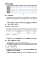
4.2.1 Aggregate Groups
SIGNAMAX series industrial switches supports 13 link aggregation groups.
Configuration steps:
Step 1 Select Trunk ID. There are 13 groups(T1 ~ T13 );
Step 2 Specify the trunk name;
Step 3 Specify the trunk type;
Manual: a manual trunk can only be manually set or deleted; LACP can be
disabled.
Static: a static LACP trunk can only be manually set or deleted; any port in a
static LACP trunk shall enable LACP protocol. When a static LACP
trunk is (manually) deleted, all ports of this trunk with “up” status will
generate one or more dynamic LACP trunks automatically.
Step 4 Select the ports as members of an aggregate group (2 ~ 8 ports);
Step 5 Click <Apply>, and then the link-aggregation Information will be listed at the
lower part.
Note: A trunk may be configured as a mirroring port, but it is not allowed to
configure a trunk as a monitoring port.

4 Port Management
4-3
Caution:
If LACP (Link Aggregation Control Protocol) is disabled in Advanced
Configuration, you can only configure port aggregration manually, so If you
want to configure port aggregation statically, you need to enable LACP in
Advanced Configuration
.
The ports of the same link-aggregration group should have the same basic
configuration, such as STP, QoS, VLAN and port attribute and so on.
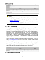
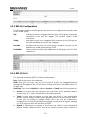
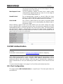
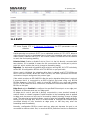
4.2.2 LACP Port Setting
On this page, you can configure dynamic LACP aggregation. A dynamic LACP trunk
can only be set or deleted automatically by the protocol. This protocol is based on
IEEE802.3ad and uses LACPDUs (link aggregation control protocol data unit) to
interact with its peer. After LACP is enabled on a port, LACP notifies the following
information of the port to its peer by sending LACPDUs: priority and MAC address of
this system, priority, number and operation key of the port. Upon receiving the
information, the peer compares the information with the information of other ports on
the peer device to determine the ports that can be aggregated. In this way, the two
parties can reach an agreement in adding/removing the port to/from a dynamic
aggregation group. Any port in a dynamic LACP trunk shall have this port’s LACP
enabled.
Two link aggregation groups are configured, including Ethernet port 0/1, 0/3, 0/7 and
0/8 in 4.2.1 Aggregate Groups
. So Ethernet port 0/2, 0/4, 0/5 to 0/6 can be configured
as dynamic LACP ports.
A dynamic LACP aggregation group is automatically created and removed by the
system. Users cannot add/remove ports to/from it. A port can participate in dynamic
link aggregation only when it is LACP-enabled. Ports can be aggregated into a
dynamic aggregation group only when they are connected to the same peer device
and have the same basic configuration (such as rate and duplex mode).
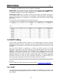
4.2.3 Aggregate Basic Setting

4 Port Management
4-4
LACP determines the dynamic aggregation group members according to the priority of
the port ID on the end with the preferred device ID. The device ID consists of two-byte
system priority and six-byte system MAC address, that is, device ID = system priority +
system MAC address.
When two device IDs are compared, the system priorities are compared first, and the
system MAC addresses are compared when the system priorities are the same. The
device with smaller device ID will be considered as the preferred one.
There is a limit on the number of selected ports in an aggregation group. Therefore, if
the number of selected ports in an aggregation group exceeds the maximum member
port number supported by the device, the system will choose the ports with lower port
numbers as the member ports.
Set LACP system priority (from 1 to 65535).
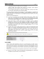
4.2.4 LACP Status Setting
Set LACP port status as active or passive.
Passive The port does not automatically send LACP protocol packets; it
responds only if it receives an LACP protocol packet from the peer
device.
Active The port automatically sends LACP protocol packets.
A link having either one or two active LACP ports can perform dynamic LACP trunking.
If the two LACP ports connected are passive, they will not perform dynamic LACP
trunking as both ports are waiting for LACP protocol packet from the peer device.
Note:
The dynamic active LACP ports on this device can aggregate with the active or
passive LACP ports of the peer devices, but the passive LACP ports of this device
can only aggregate with the active LACP ports of the peer devices.
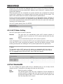
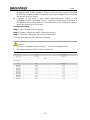
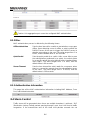
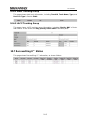
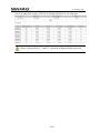
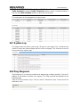
4.3 Port Bandwidth
You can configure the egress traffic limit on individual ports, so as to keep normal
network service. The bottom of the page will show the rate limit list.
Port Select the port to configure
Egress The desired egress rate limit to be configured. Choose “disabled” to
set the port with no egress rate limit, which means the port will run in
full speed for egress traffic. You can also select a specific egress rate
from the drop-down list for a port.

4 Port Management
4-5
When completing the configuration, click <apply> to take effect. The lower part of this
page shows a full list of rate limit for each port.
Note: The Egress status of Ethernet 0/1, 0/3, 0/7 and 0/8 are displayed gray, they
cannot be condigured the egress rate, because they are aggregration ports.
Caution: Egress rate cannot be enabled on the aggregration ports.
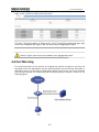
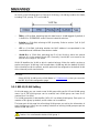
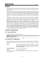
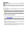
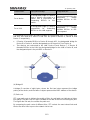
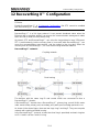
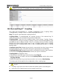
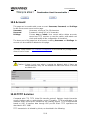
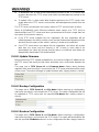
4.4 Port Mirroring
Port mirroring refers to the process of copying the packets received or sent by the
specified port to the destination port for packet analysis and monitoring. Generally, a
destination port is connected to a data detect device, which users can use to analyze
the mirrored packets for monitoring and troubleshooting the network, shown as the
following figure:

4 Port Management
4-6
Configuration steps:
Step 1 Enable/disable mirroring state;
Step 2 If mirroring state is enabled, choose a port as the monitoring port;
Caution:
Monitoring port cannot be link-aggregration port;
Only one port can be selected as monitoring port;
Monitoring port cannot be mirroring port at the same time.
Step 3 Select the mirroring ports and whether the packets to be mirrored are Rx, Tx
or both Rx /Tx.
None: Means to mirror none packets on the port;
Rx Port: Means only to mirror the packets received by the port;
Tx Port: Means only to mirror the packets sent by the port;
Rx /Tx Port: Means to mirror the packets received and sent by the port.
Step 4 Click <Apply> to make it effective.

5 VLAN
5-1
5 VLAN
The traditional Ethernet is a broadcast network, where all hosts are in the same
broadcast domain and connected with each other through hubs or switches. The hub is
a physical layer device without the switching function, so it forwards the received
packet to all ports. The switch is a link layer device which can forward the packet
according to the MAC address of the packet. However, when the switch receives a
broadcast packet or an unknown unicast packet whose MAC address is not included in
the MAC address table of the switch, it will forward the packet to all the ports except
the inbound port of the packet. In this case, a host in the network receives a lot of
packets whose destination is not the host itself. Thus, plenty of bandwidth resources
are wasted, causing potential serious security problems.
The traditional way to isolate broadcast domains is to use routers. However, routers
are expensive and provide few ports, so they cannot subnet the network particularly.
The virtual local area network (VLAN) technology is developed for switches to control
broadcast in LANs.
By creating VLANs in a physical LAN, you can divide the LAN into multiple logical
LANs, each of which has a broadcast domain of its own. Hosts in the same VLAN
communicate with each other as if they are in a LAN. However, hosts in different
VLANs cannot communicate with each other directly.
This managed switch supports 802.1Q VLAN and port-based VLAN. VLAN is in 802.1Q
mode in default configuration.
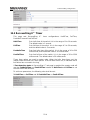
5.1 Advanced
This page globally sets the VLAN mode from the following: NO VLAN, port-based VLAN
and 802.1Q VLAN.
5.2 Port-based VLAN

5 VLAN
5-2
Port-based VLAN technology introduces the simplest way to classify VLANs. You can
isolate the hosts and divide them into different virtual workgroups through assigning the
ports on the device connecting to hosts to different VLANs.
This way is easy to implement and manage and it is applicable to hosts with relatively
fixed positions.
Note:
Select Port-based VLAN from the VLAN Mode in 5.1 Advanced page, so that you
can enter the Port-based VLAN configuration page.
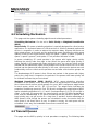
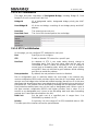
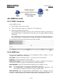
On its page, the user can create a new VLAN group with specific VID and VLAN group
name. Up to 255 VLAN groups can be created; each VLAN group can have an ID
number from 1 to 255.
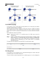
Configuration Example:
As in the following figure, a VLAN is configured, whose VID is 1 and name is
VLAN0001 by default, and the member ports are Ethernet 0/6 and the T2 aggregation
group. It means that the devices connecting with Ethernet 0/6 and T2 can
communicate with each other, but they cannot communicate with other VLAN.
The configured VLAN can be modified or deleted. The lower part of this page lists all
port-based VLAN groups configured; they can be modified or deleted.
5.3 802.1Q VLAN
VLAN tags in the packets are necessary for the switch to identify packets of different
VLANs. The switch works at Layer 2 and it can identify the data link layer
encapsulation of the packet only, so you can add the VLAN tag field into only the data
link layer encapsulation if necessary.
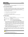
In 1999, IEEE issues the IEEE 802.1Q protocol to standardize VLAN implementation,
defining the structure of VLAN-tagged packets.
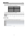
In traditional Ethernet data frames, the type field of the upper layer protocol is
encapsulated after the destination MAC address and source MAC address, as shown
in the follow figure of Encapsulation format of traditional Ethernet frames.
DA refers to the destination MAC address, SA refers to the source MAC address, and
Type refers to the protocol type of the packet. IEEE 802.1Q protocol defines that a
4-byte VLAN tag is encapsulated after the destination MAC address and source MAC
Page is loading ...
Page is loading ...
Page is loading ...
Page is loading ...
Page is loading ...
Page is loading ...
Page is loading ...
Page is loading ...
Page is loading ...
Page is loading ...
Page is loading ...
Page is loading ...
Page is loading ...
Page is loading ...
Page is loading ...
Page is loading ...
Page is loading ...
Page is loading ...
Page is loading ...
Page is loading ...
Page is loading ...
Page is loading ...
Page is loading ...
Page is loading ...
Page is loading ...
Page is loading ...
Page is loading ...
Page is loading ...
Page is loading ...
Page is loading ...
Page is loading ...
Page is loading ...
Page is loading ...
Page is loading ...
Page is loading ...
Page is loading ...
Page is loading ...
Page is loading ...
Page is loading ...
Page is loading ...
Page is loading ...
Page is loading ...
Page is loading ...
Page is loading ...
Page is loading ...
Page is loading ...
Page is loading ...
Page is loading ...
Page is loading ...
Page is loading ...
Page is loading ...
Page is loading ...
Page is loading ...
Page is loading ...
Page is loading ...
Page is loading ...
Page is loading ...
Page is loading ...
Page is loading ...
Page is loading ...
Page is loading ...
Page is loading ...
-
 1
1
-
 2
2
-
 3
3
-
 4
4
-
 5
5
-
 6
6
-
 7
7
-
 8
8
-
 9
9
-
 10
10
-
 11
11
-
 12
12
-
 13
13
-
 14
14
-
 15
15
-
 16
16
-
 17
17
-
 18
18
-
 19
19
-
 20
20
-
 21
21
-
 22
22
-
 23
23
-
 24
24
-
 25
25
-
 26
26
-
 27
27
-
 28
28
-
 29
29
-
 30
30
-
 31
31
-
 32
32
-
 33
33
-
 34
34
-
 35
35
-
 36
36
-
 37
37
-
 38
38
-
 39
39
-
 40
40
-
 41
41
-
 42
42
-
 43
43
-
 44
44
-
 45
45
-
 46
46
-
 47
47
-
 48
48
-
 49
49
-
 50
50
-
 51
51
-
 52
52
-
 53
53
-
 54
54
-
 55
55
-
 56
56
-
 57
57
-
 58
58
-
 59
59
-
 60
60
-
 61
61
-
 62
62
-
 63
63
-
 64
64
-
 65
65
-
 66
66
-
 67
67
-
 68
68
-
 69
69
-
 70
70
-
 71
71
-
 72
72
-
 73
73
-
 74
74
-
 75
75
-
 76
76
-
 77
77
-
 78
78
-
 79
79
-
 80
80
-
 81
81
-
 82
82


SignaMax Managed Layer 2 Industrial Switch User guide
- Category
- Network switches
- Type
- User guide
- This manual is also suitable for
Ask a question and I''ll find the answer in the document
Finding information in a document is now easier with AI
Related papers
-
 SignaMax 24-Port 10/100/1000 Managed Layer 2 PoE Switches User guide
-
 SignaMax 065-7861 Product information
-
 SignaMax 24-Port 100/1000 Managed Layer 2+ SFP Switch Plus 4 10GbE SFP+ Ports User guide
-
 SignaMax 24-Port 10/100/1000 Managed Layer 2 SFP Switch Plus 4 10 GbE SFP Ports User guide
-
 SignaMax 24-Port 10/100/1000 Managed Layer 2 PoE Switches User manual
-
 SignaMax 10/100/1000 to 100/1000 OAM Managed Media Converters User guide
-
 SignaMax 2-Port 10/100 Unmanaged Compact Industrial Switch User guide
-
 SignaMax OAM Managed Dual Rate Converter Series User manual
-
 SignaMax 10/100 to 100FX Industrial Media Converters User guide
-
 SignaMax 10/100 Ethernet Extender User guide


Other documents
-
 XNET SG9224B Web User Manual
-
Linksys LGS308P User manual
-
 Dymec KY-3000EMD Multilingual Industrial Ethernet Switch User manual
-
H3C S6850-56HF Configuration manual
-
 First Virtual Communications 065-7710 User manual
-
-
Allied Telesis AT-IFS802SP User manual
-
-
Comnet CWGE10FX2TX8MS User manual
-
AFi SMH10p-PoE Owner's manual


