MODEL TTS 200
GPS Time Server
INSTRUCTION MANUAL
95 Methodist Hill Drive
Suite 500
Rochester, NY 14623
Phone: 585.321.5800
Fax: 585.321.5219
www.spectracomcorp.com
Revisions, if any, are located at the end of the manual.
Part number 1125-5000-0050
Manual Revision C
December 2004
Current to software version 2.2.0
Copyright© 2004 Spectracom Corporation. All rights
reserved. Contents of this publication may not be
reproduced in any form without the written permission
of Spectracom Corporation
SPECTRACOM 95 Methodist Hill Drive Suite 500 Rochester, NY 14623
+1.585.321.5800 FAX: +1.585.321.5218 www.spectracomcorp.com sales@spectracomcorp.com

SPECTRACOM 95 Methodist Hill Drive Suite 500 Rochester, NY 14623
+1.585.321.5800 FAX: +1.585.321.5218 www.spectracomcorp.com sales@spectracomcorp.com
SPECTRACOM 5-YEAR WARRANTY
LIMITED WARRANTY
Spectracom warrants each new product manufactured and sold by
it to be free from defects in software, material, workmanship, and
construction, except for batteries, fuses, or other material normally
consumed in operation that may be contained therein AND AS
NOTED BELOW, for five years after shipment to the original
purchaser (which period is referred to as the “warranty period”).
This warranty shall not apply if the product is used contrary to the
instructions in its manual or is otherwise subjected to misuse,
abnormal operations, accident, lightning or transient surge, repairs
or modifications not performed by Spectracom.
The GPS receiver is warranted for one year
from date of shipment and subject to the
exceptions listed above. The power adaptor, if
supplied, is warranted for one year from date of
shipment and subject to the exceptions listed
above.
THE ANALOG CLOCKS ARE WARRANTED FOR ONE YEAR
FROM DATE OF SHIPMENT AND SUBJECT TO THE EXCEPTIONS
LISTED ABOVE.
THE TIMECODE READER/GENERATORS ARE WARRANTED FOR
ONE YEAR FROM DATE OF SHIPMENT AND SUBJECT TO THE
EXCEPTIONS LISTED ABOVE.
The Rubidium oscillator, if supplied, is warranted for two years from
date of shipment and subject to the exceptions listed above.
All other items and pieces of equipment not specified above,
including the antenna unit, antenna surge suppressor and antenna
pre-amplifier are warranted for 5 years, subject to the exceptions
listed above.
WARRANTY CLAIMS
Spectracom’s obligation under this warranty is limited to in-factory
service and repair, at Spectracom’s option, of the product or the
component thereof, which is found to be defective. If in
Spectracom’s judgment the defective condition in a Spectracom
product is for a cause listed above for which Spectracom is not
responsible, Spectracom will make the repairs or replacement of
components and charge its then current price, which buyer agrees
to pay.
Spectracom shall not have any warranty obligations if the
procedure for warranty claims is not followed. Users must notify
Spectracom of the claim with full information as to the claimed
defect. Spectracom products shall not be returned unless a return
authorization number is issued by Spectracom.
Spectracom products must be returned with the description of the
claimed defect and identification of the individual to be contacted
if additional information is needed. Spectracom products must be
returned properly packed with transportation charges prepaid.
Shipping expense: Expenses incurred for shipping Spectracom
products to and from Spectracom (including international customs
fees) shall be paid for by the customer, with the following
exception. For customers located within the United States, any
product repaired by Spectracom under a “warranty repair” will be
shipped back to the customer at Spectracom’s expense unless
special/faster delivery is requested by customer.
Spectracom highly recommends that prior to returning equipment for
service work, our technical support department be contacted to
provide trouble shooting assistance while the equipment is still
installed. If equipment is returned without first contacting the
support department and “no problems are found” during the repair
work, an evaluation fee may be charged.
EXCEPT FOR THE LIMITED WARRANTY STATED ABOVE,
SPECTRACOM DISCLAIMS ALL WARRANTIES OF ANY KIND
WITH REGARD TO SPECTRACOM PRODUCTS OR OTHER
MATERIALS PROVIDED BY SPECTRACOM, INCLUDING
WITHOUT LIMITATION ANY IMPLIED WARRANTY OR
MERCHANTABILITY OR FITNESS FOR A PARTICULAR PURPOSE.
Spectracom shall have no liability or responsibility to the original
customer or any other party with respect to any liability, loss, or
damage caused directly or indirectly by an Spectracom product,
material, or software sold or provided by Spectracom, replacement
parts or units, or services provided, including but not limited to any
interruption of service, excess charges resulting from malfunctions of
hardware or software, loss of business or anticipatory profits
resulting from the use or operation of the Spectracom product or
software, whatsoever or howsoever caused. In no event shall
Spectracom be liable for any direct, indirect, special or
consequential damages whether the claims are grounded in
contract, tort (including negligence), or strict liability.
EXTENDED WARRANTY COVERAGE
Extended warranties can be purchased for additional periods
beyond the standard five-year warranty. Contact Spectracom no
later than the last year of the standard five-year warranty for
extended coverage.

TTS200 Manual Rev C 3
Table of Contents
1 GENERAL INFORMATION ...........................................................................................................1
1.1 Introduction............................................................................................................................................... 1
1.2 Warranty Information and Product Support ........................................................................................2
1.3 Unpacking.................................................................................................................................................. 3
1.3.1 Package Contents................................................................................................................................ 3
1.4 Model TTS 200 Specifications.................................................................................................................. 4
1.4.1 Receiver .............................................................................................................................................. 4
1.4.2 RS-232 Setup Port............................................................................................................................... 4
1.4.3 10/100 Ethernet Port ........................................................................................................................... 4
1.4.4 Protocols supported............................................................................................................................. 4
1.4.5 RS-232 Communication Port.............................................................................................................. 5
1.4.6 RS-485 Output .................................................................................................................................... 5
1.4.7 Front Panel LED Indicators ................................................................................................................ 5
1.4.8 Relay Outputs...................................................................................................................................... 5
1.4.9 Input Power......................................................................................................................................... 6
1.4.10 Mechanical and Environmental .......................................................................................................... 6
2 INSTALLATION ............................................................................................................................7
2.1 Power and Ground Connection ............................................................................................................... 7
2.2 GPS Antenna Installation......................................................................................................................... 8
2.2.1 Antenna Cable for Outdoor Antenna .................................................................................................. 8
2.2.2 Cable Lengths ..................................................................................................................................... 8
2.2.3 Model 8226 Impulse Suppressor ........................................................................................................ 8
2.2.4 Model 8227 GPS Inline Amplifier...................................................................................................... 9
2.3 Ethernet Network Cabling..................................................................................................................... 10
2.4 RS-485 Wiring and Set up...................................................................................................................... 11
2.4.1 Remote Connections ......................................................................................................................... 11
2.4.2 Remote Output Usage....................................................................................................................... 12
2.4.3 RS-485 Guidelines............................................................................................................................ 12
2.4.4 Connection Method........................................................................................................................... 13
2.4.5 Termination....................................................................................................................................... 17
3 PRODUCT CONFIGURATION....................................................................................................19
3.1 Network Configuration .......................................................................................................................... 19
3.1.1 Using the Web Interface to Configure the Network ......................................................................... 19
3.1.2 Login................................................................................................................................................. 21
3.1.3 To Change the Default Login Password Values............................................................................... 23
3.2 NTP/SNTP ............................................................................................................................................... 24
3.2.1 Configure NTP.................................................................................................................................. 24

TTS200 Manual Rev C 4
3.2.2 NTP Support ..................................................................................................................................... 25
3.2.3 Application Note: MD5 Authentication using a Cisco Router ........................................................ 26
3.3 Local System Clocks Setup .................................................................................................................... 27
3.3.1 Time Zone and DST.......................................................................................................................... 30
3.4 Interface Setup ........................................................................................................................................ 33
3.5 Alarms...................................................................................................................................................... 35
3.5.1 Alarm Outputs................................................................................................................................... 35
3.5.2 Alarm log .......................................................................................................................................... 35
3.6 Relays ....................................................................................................................................................... 37
3.6.1 Configuring the relays....................................................................................................................... 37
3.7 Event Timer............................................................................................................................................. 39
3.7.1 Configuring the Event Timer............................................................................................................ 39
3.8 Logs .......................................................................................................................................................... 43
3.8.1 Display Alarm Log ........................................................................................................................... 43
3.8.2 Display Dial Out Log........................................................................................................................ 43
3.8.3 Display Operational Log................................................................................................................... 44
3.8.4 Display Oscillator Log...................................................................................................................... 46
3.8.5 NTP Statistics.................................................................................................................................... 48
3.8.6 Display Event Relay Log .................................................................................................................. 49
3.8.7 GPS Qualification Log...................................................................................................................... 49
3.9 SNMP ....................................................................................................................................................... 51
3.9.1 SNMP Configuration ........................................................................................................................ 51
3.9.2 Spectracom MIB ............................................................................................................................... 52
3.9.3 SNMP Support.................................................................................................................................. 53
4 OPERATION ...............................................................................................................................54
4.1 Status Indicator....................................................................................................................................... 54
4.2 GPS........................................................................................................................................................... 55
4.2.1 GPS Operation .................................................................................................................................. 55
4.2.2 Set System Mode .............................................................................................................................. 56
4.2.3 GPS Signal Status ............................................................................................................................. 57
4.2.4 Reception Troubleshooting............................................................................................................... 61
5 TROUBLESHOOTING ................................................................................................................63
5.1 Front Panel Power and Sync Lamps..................................................................................................... 63
5.2 Front Panel LAN Connector.................................................................................................................. 64
5.3 Customer Service .................................................................................................................................... 65
6 APPENDICES .............................................................................................................................66

TTS200 Manual Rev C 5
6.1 Software Commands............................................................................................................................... 66
6.2 Serial Data Formats................................................................................................................................ 83
6.3 SW License Notices................................................................................................................................. 91

TTS200 Manual Rev C 6
List of Figures
Figure 2.2-1: Model 8226 Impulse Suppressor ....................................................................................9
Figure 2.2-2: Model 8227 Inline Amplifier ............................................................................................9
Figure 2.4-1: Remote Outputs............................................................................................................11
Figure 2.4-2: RS-485 Output..............................................................................................................11
Figure 2.4-3: One-Way Bus Installation .............................................................................................13
Figure 2.4-4: Split Bus Configuration .................................................................................................14
Figure 2.4-5: Wire Strain Relief..........................................................................................................15
Figure 2.4-6: TimeView RS-485 Interface..........................................................................................16
Figure 2.4-7: Model 8179T TimeTap RS-485 Interface......................................................................16
Figure 2.4-8: Model 9188/8188 RS-485 Interface..............................................................................17
Figure 2.4-9: TimeBurst RS-485 Interface .........................................................................................17
Figure 3.1-1: Log-in Permissions .......................................................................................................22
Figure 3.2-1: NTP Screen ..................................................................................................................24
Figure 3.3-1 Local System Clocks Setup Screen................................................................................27
Figure 3.3-2 Time Zone and DST Setup Screen.................................................................................28
Figure 3.4-1: Interface Screen ............................................................................................................34
Figure 3.5-1: Alarm Setup Screen......................................................................................................36
Figure 3.6-1 Relay Output Screen .....................................................................................................37
Figure 3.7-1: Event Timer Relay Screen............................................................................................39
Figure 3.7-2 Event Timer Relay Screen..............................................................................................40
Figure 3.8-1 NTP Statistics .................................................................................................................48
Figure 3.9-1: SNMP Setup Screen.....................................................................................................51
Figure 4.2-1: GPS Set-up Screen ......................................................................................................55
Figure 4.2-2: GPS Signal Status Setup Screen .................................................................................57

TTS200 Manual Rev C 7
List of Tables
Table 2-1: Cable Sources for RS-485 Lines Over 1500 Feet.............................................................12
Table 2-2: Cable Sources for RS-485 Lines Under 1500 Feet...........................................................13
Table 4-1: Status Indicator.................................................................................................................54
Table 4-2: Typical Antenna Cable Resistance Values .......................................................................61
Table 6-1: Alphabetical List of Commands ........................................................................................66
Table 6-2: Table of Quality Indicators ................................................................................................85

TTS200 Manual Rev C Page 1
1 General Information
1.1 Introduction
Spectracom Corporation is a leading manufacturer of synchronized, precise time-keeping devices
meeting the demands for accuracy, reliability and trace ability in mission-critical systems across
networks. Our NetClock is a direct response to customer needs for cutting-edge synchronization
technology at an affordable price.
Spectracom NetClock Master Clocks are based on GPS (Global Positioning System) technology –
tracking up to twelve satellites simultaneously and synchronized to their atomic clocks. This enables
computer networks to synchronize all elements of network hardware and software (including system
logs) down to the millisecond over LANs or WANs – anywhere on the planet.
Technology advancements, including an embedded processor, make it possible to obtain Legally
Traceable Time™ tags on log files and simplify digital forensics. The NetClock allows users to
accurately time stamp video surveillance systems, access points, card readers, time clocks and alarm
systems to provide necessary evidence and validation of events.
Set-up and reporting are web-enabled – a NetClock can be accessed, under appropriate security
policies, anywhere within a network. The product features browser-based remote diagnostics,
configuration and control as well as Flash memory for remote software upgrades. A 10/100 Mbps
Ethernet LAN port provides support for Network Time Protocol (NTP) over a variety of platforms
including Win2K and XP, Win 95/98/ME, NT, Cisco, UNIX, Linux and more. Remote control and
monitoring can also be done through SNMP and Telnet.
Time code outputs are available to meet the requirements of diverse systems – RS-232 serial ports,
RS-485 data bus ports. Alarm outputs and programmable timer outputs are also provided.
The NetClock Master Clock system includes a CE/UL-approved power supply for international use,
GPS antenna and associated mounting hardware.

TTS200 Manual Rev C 2
1.2 Warranty Information and Product Support
Warranty information is found on the leading pages of this manual.
Spectracom continuously strives to improve its products and therefore greatly appreciates any and all
customer feedback given. Please participate in Spectracom’s Customer Satisfaction Survey found on
our web site at:
http://www.spectracomcorp.com/
The online survey is also used for warranty registration of your new Spectracom products. All
completed entries are automatically entered into a monthly prize give away drawing.
Technical support is available by telephone. Please direct any comments or questions regarding
application, operation, or service to Spectracom Customer Service Department. Customer Service is
available Monday through Friday from 8:00 A. M. to 5:00 P.M. Eastern time.
Telephone Customer Service at: 585-321-5800.
In addition, please contact customer service to obtain a Return Material Authorization Number
(RMA#) before returning any instrument to Spectracom Corporation. Please provide the serial
number and failure symptoms. Transportation to the factory is to be prepaid by the customer. After
obtaining an RMA# ship the unit back using the following address:
Spectracom Corporation
Repair Department, RMA# xxxxx
95 Methodist Hill Drive, Suite 500
Rochester, NY 14623
Product support is also available by e-mail. Questions on equipment operation and applications may
be e-mailed to Spectracom Sales Support at:
mailto:[email protected]
Repair or technical questions may be e-mailed to Spectracom Technicians at:
mailto:[email protected]
Visit our web page for product information, application notes and upgrade notices as they become
available at:
http://www.spectracomcorp.com/

TTS200 Manual Rev C 3
1.3 Unpacking
Upon receipt, carefully examine the carton and its contents. If there is damage to the carton that
results in damage to the unit, contact the carrier immediately. Retain the carton and packing materials
in the event the carrier wishes to witness the shipping damage. Failing to report shipping damaging
immediately may forfeit any claim against the carrier. In addition, notify Spectracom Corporation of
shipping damage or shortages, to obtain a replacement or repair services.
Remove the packing list from the envelope on the outside of the carton. Check the packing list
against the contents to be sure all items have been received, including an instruction manual and
ancillary kit.
1.3.1 Package Contents
1. Unit
2. User manual
3. CE/UL-approved power supply for international use
4. AC power cord
5. Rack mount kit (2 ears, 4 side screws)
6. Rubber footpads for desktop installation
7. Two 3-pin terminal block connector for RS-485 connections
8. 10-pin terminal block connector
9. Terminating Resistor, 120Ω
Spectracom models that have the modem dial out feature will also receive the following:
10. Serial Modem kit
11. Null modem adapter

TTS200 Manual Rev C 4
1.4 Model TTS 200 Specifications
1.4.1 Receiver
Received standard: L1 C/A Code transmitted at 1575.42 MHz.
Satellites tracked: Up to twelve simultaneously.
Acquisition time: Typically <4 minutes from a cold start.
Antenna requirements: Active antenna module, +5V, powered by the NetClock, with 18 to 36 dB
gain
Antenna connector: Type N, female.
1.4.2 RS-232 Setup Port
Function: Accepts commands to locally configure the IP network parameters for
initial connectivity
Connector: DB9 female, pin assignments conform to EIA/TIA-574 standard, data
communication equipment
Character structure: ASCII, 9600 baud, 1 start, 8 data, 1 stop, no parity.
1.4.3 10/100 Ethernet Port
Function: 10/100 Base T auto sensing LAN connection for NTP and remote
monitoring, diagnostics, configuration and upgrade.
1.4.4 Protocols supported
NTP: Networked NTP Stratum 1 Time Server (RFC 1305), SNTP (RFC 1361)
Security: MD5 Security
Loading: 675 requests per second without encryption.
345 requests per second with encryption.
Accuracy: Output jitter within +/-50 microseconds of UTC typical.
Clients supported: Up to 128 users may be supported in a single sub-network.
A gateway greatly increases the number of users.
HTTP Server: For browser-based configuration and monitoring using Internet Explorer 5
or Netscape 6 per RFC 1945 and 2068.
FTP: For remote upload of event logs and download of upgrades per RFC 959.
SNMP: As of release 1.2.0 (future) will support v1, v2, v2c, and v3. Compliant
with RFCs 1155, 1157, 1212, 1213, 12 15, 1901-8.
Telnet: For limited remote configuration per RFC 854.
Security Features: Up to 16-character Telnet password, Telnet Disable, TFTP Disable, SNMP
Disable and MD5 Authentication.
Connector: RJ-45, Network IEEE 802.3.

TTS200 Manual Rev C 5
1.4.5 RS-232 Communication Port
Signal: Selected time Data Format in RS-232 levels when interrogated by the
connected device. This port may also be configured to provide a
continuous once-per-second output.
Connector: DB9 female, pin assignments conform to EIA/TIA-574 standard, data
communication equipment (DCE). No flow control.
Character structure: ASCII, 1 start, 8 data, 1 stop, and no parity.
Accuracy: Data stream on time marker within ± 100 microseconds of UTC on Sync in
Formats 0, 1, and 3. Formats 2 and 4 within ±1 millisecond of UTC.
Configuration: Baud rate and output Data Formats are selected using the web interface.
Bit rate selections are 1200, 2400, 4800 and 9600 baud. There are six
Data Format selections available.
1.4.6 RS-485 Output
Signal: Selected time Data Format in RS-485 levels, output once-per-second.
Connector: Removable 3-position terminal block (supplied).
Character structure: ASCII, 1 start, 8 data, 1 stop, and no parity.
Accuracy: Data stream on time marker within ± 100 microseconds of UTC on Sync.
Configuration: Baud rate and output Data Formats are selected using the web interface.
Bit rate selections are 1200, 2400, 4800, and 9600 baud. There are six
Data Format selections available.
1.4.7 Front Panel LED Indicators
Power: Green, always on
Sync: Tri-color LED indicates the time data accuracy and equipment fault
LAN: Green: Good Link indicator
Yellow: activity
1.4.8 Relay Outputs
Three separate outputs provided for either Programmable Event Timer Output or Major/Minor Alarm
indication.
Relay contacts: NO, NC, and Common.
Contact rating: 30 VDC, 2 amps.
Connector: 10-position 3.81 mm terminal block (mate supplied).
Programmable Timer Output:
128 On/Off events standard, 1024 events optional. Timer events that are
hourly, daily or weekly only count as a single event so many events can
be programmed in even the standard product.
Major/Minor Alarms: Relay contacts allow remote monitoring of operational status. A power
failure, CPU failure loss of time sync, etc cause the alarm relay to de-

TTS200 Manual Rev C 6
energize. The alarm relay returns to normal operation (energized) when
the fault condition is corrected.
1.4.9 Input Power
Power source: 90 to 240 VAC, 47 to 63 Hz through an IEC 320 universal connector.
North American AC power cord supplied. AC cables for other countries
available locally.
DC input: 9.5 to 30 VDC, 10 watts, through a CE/UL/CSA-approved power adapter
(supplied).
Connector: Barrel, 5.5mm O.D., 2.5 mm I. D.
Polarity: Negative shell, positive center.
1.4.10 Mechanical and Environmental
Dimensions: EIA 19” rack mount W x 1.75” H [1U] x 11.00” D
(483 mm W x 44 mm H x 305 mm D).
Weight: 4.8 lbs. (2.2 kg).
Temperature: 32° to 122°F (0° to 50°C) operating range.
-40° to 185°F (-40° to 85°C) storage range
Humidity: 10% - 95% relative humidity, non-condensing

TTS200 Manual Rev C 7
2 Installation
2.1 Power and Ground Connection
An external AC to DC power adapter powers the NetClock.
The adapter is available in two forms:
1. US Only Wall Mount adapter, which plugs into any standard North American outlet.
2. The International and US Desk Top adapter, which has a detachable AC power cord to an IEC
320 connector.
This power adapter is shipped with a line cord compatible with AC receptacles (NEMA 5-15R)
commonly found in the United States and Canada. Alternate type line cords or adapters may be
obtained locally.
The chassis ground stud allows the NetClock chassis to be connected to an earth ground or single
point ground. Connecting the chassis to a single point ground system may be required in some
installations to ensure optimum lightning protection. An earth ground is also recommended in
installations where excessive noise on the power line degrades receiver performance.
Note: Auto Negotiate, which determines the network settings to use, only occurs at power-on.
Always connect the Ethernet cable before powering-on the unit for the first time. If the Ethernet cable
is connected after power-on, the unit will default to 10 Mbps and half duplex.

TTS200 Manual Rev C 8
2.2 GPS Antenna Installation
2.2.1 Antenna Cable for Outdoor Antenna
When using the Model 8225 GPS outdoor antenna, Spectracom recommends using LMR-400 low
loss type cable, Spectracom CAL7xxx for the GPS antenna cable. RG-213 type coax, such as
Belden 8267,may also be used but low loss cable offers the best performance. To simplify the
installation process, Spectracom offers GPS cable assemblies terminated with Type N Male
connectors. Specify part number CAL7xxx, where xxx equals the length in feet. Standard lengths
are 10, 25, 50, 100, 150 and 200 feet.
If the antenna cable is purchased locally, select coax suitable for outdoor use. Consider the cable's
weather ability, temperature range, UV resistance, and attenuation characteristics.
Do not allow the antenna cable to be placed in standing water, as water may permeate through the
coax jacket over time. On flat roof installations, the coax can be suspended by cable hangers or
placed in sealed PVC conduit. Apply a weather proofing sealant or tape over all outdoor connections.
Installation of a surge protection device in the antenna line is recommended to protect the NetClock
receiver and connected devices from lightning damage. Spectracom offers the Model 8226 Impulse
Suppressor to shunt potentially damaging voltages on the antenna coax to ground. Refer to the
Model 8226 Impulse Suppressor Section for a complete description of the Model 8226.
2.2.2 Cable Lengths
Using Spectracom CAL7xxx or Times Microwave LMR-400 coax, the maximum antenna cable length
permitted is 200 feet because the 91XX series allows 12 dB loss. An amplifier is needed whenever
antenna cable lengths exceed 200 feet. Installations requiring longer antenna cables may use the
Model 8227 Inline Amplifier, or lower loss cable. Refer to the Model 8227 Section for additional
information on the Model 8227.
When selecting alternate antenna cable sources, the attenuation characteristics at the GPS
frequency of 1575.42 MHz must be known. To ensure optimum receiver performance, the total
antenna cable attenuation must not exceed 12 dB. Cable attenuation of greater than 12 dB requires
the use of a Model 8227 Inline Amplifier.
2.2.3 Model 8226 Impulse Suppressor
Spectracom recommends the use of an inline coaxial protector for all products with an outside
antenna. Spectracom offers the Model 8226, Impulse Suppressor, to protect the receiver from
damaging voltages occurring on the antenna coax. Voltages exceeding the impulse suppresser trip
point are shunted to the system ground. The Model 8226 is designed to withstand multiple surges.
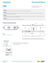
Mount the suppressor indoors, preferably where the coax enters the building. Install the suppressor
on a grounding panel or bulkhead as shown in Figure 2.2-1.

TTS200 Manual Rev C 9
MOUNTING
HOLE PATTERN
SINGLE POINT GROUNDING
PANEL OR BULKHEAD
.0625 inch (15.88mm)
DIAMETER
.203 inch (5.16mm)
DIAMETER
INSTALL "O" RING
Figure 2.2-1: Model 8226 Impulse Suppressor
Refer to the Model 8226 Manual for proper installation.
2.2.4 Model 8227 GPS Inline Amplifier
An inline amplifier is required whenever GPS antenna cable lengths cause greater than 12 dB
attenuation. Using Spectracom CAL7xxx coax, an amplifier is needed whenever antenna cable
lengths exceed 200 feet.
The Model 8227 GPS Inline Amplifier, shown in Figure 2.2-2, extends the maximum cable length to
600 feet. The Model 8227 provides 20 dB of gain and is powered by the NetClock/ receiver.
Figure 2.2-2: Model 8227 Inline Amplifier
Refer to the Model 8227 Manual for proper installation.

TTS200 Manual Rev C 10
2.3 Ethernet Network Cabling
Spectracom’s 91xx products provide a 10/100 Ethernet port for full NTP functionality as well as full
web enabled configuration, monitoring and diagnostic support.
The Ethernet port is provided on the front panel for easy connection to routers and hubs.
• Use standard CAT 5 cable with RJ45 connectors.
• When connecting to a hub or router use a straight-through wired cable.
• When connecting directly to a PC, use a crossover wired cable.

TTS200 Manual Rev C 11
2.4 RS-485 Wiring and Set up
2.4.1 Remote Connections
The NetClock has two Remote Connections labeled RS-485 1 and RS-485 2. On NetClocks without
a GPS reference, port 1 is used as a time output port and port 2 is a time input port. On NetClocks
with a GPS reference, both ports are output ports. These outputs provide a continuous once-per-
second time data stream in the selected Data Format. There are two input time Data Formats and
five-output time Data Format selections and one position data stream in NMEA 0183 format available.
Refer to Section 6.2 for a complete description of the data format structures.
In addition to Data Formats, baud rate and UTC time difference of each output is selectable. Refer to
the Interface Set-up Section 3.4 for configuring these outputs.
A 3-position terminal block is supplied in the ancillary kit for each Remote Connections. Connector
pin assignments are shown in Figure 2.4-1.
RS-485 REMOTE
Figure 2.4-1: Remote Outputs
RS-485 is a balanced differential transmission requiring twisted pair cabling.
RS-485 characteristics make it ideal to distribute time data throughout a facility. Each Remote Output
can provide time to 32 devices at cable lengths up to 4,000 feet. Refer to Figure 2.4-2 for a
schematic representation of each RS-485 output driver. Relative to RS-485 specifications, the A
terminal (Pin 2) is negative with respect to the B terminal (Pin 1) for a mark or binary 1. The A
terminal is positive to the B terminal for a space or binary 0.
1
2
3
B
A
B Terminal (+)
A Terminal (-)
Shield
Figure 2.4-2: RS-485 Output

TTS200 Manual Rev C 12
Spectracom offers many devices that accept the RS-485 data stream as an input reference. These
products include display clocks, RS-485 to RS-232 converters, NTP time provider, and radio link
products to meet various time applications and requirements. For information on Remote Output
usage refer to Section 2.4.2 of this chapter.
2.4.2 Remote Output Usage
The Remote Outputs provide a continuous once-per-second time data stream in RS-485 levels.
RS-485 is a balanced differential transmission, which offers exceptional noise immunity, long cable
runs and multiple loading. These characteristics make RS-485 ideal for distributing time data
throughout a facility. Each Remote Output can drive 32 devices over cable lengths up to 4000 feet.
Spectracom manufactures wall clocks, NTP time providers, RS-485 to RS-232 converters and radio
link products that utilize the RS-485 data stream as an input. Figure 2-5 and Figure 2.6 illustrate
typical RS-485 time data bus interconnections. Follow the guidelines listed below when constructing
the RS-485 data bus.
2.4.3 RS-485 Guidelines
Cable selection: Low capacitance, shielded twisted pair cable is recommended for installations
where the RS-485 cable length is expected to exceed 1500 feet. Table 2-1 suggests some
manufacturers and part numbers for extended distance cables. These cables are specifically
designed for RS-422 or RS-485 applications; they have a braided copper shield, nominal impedance
of 120 ohms, and a capacitance of 12 to 16 picofarads per foot.
RS-485 cable may be purchased from Spectracom. Specify part number CW04xxx, where xxx
equals the length in feet.
MANUFACTURER PART NUMBER
Belden Wire and Cable Company
1-800-BELDEN-1
9841
Carol Cable Company
606-572-8000
C0841
National Wire and Cable Corp.
232-225-5611
D-210-1
Table 2-1: Cable Sources for RS-485 Lines Over 1500 Feet

TTS200 Manual Rev C 13
For cable runs less than 1500 feet, a lower-cost twisted pair cable may be used. Refer to Table 2-2
for possible sources. In addition, Category 5 cables may be used for cable runs less than 1500 feet.
MANUFACTURER PART NUMBER
Alpha Wire Corporation
1-800-52ALPHA
5471
Belden Wire and Cable Company
1-800-BELDEN-1
9501
Carol Cable Company
606-572-8000
C0600
Table 2-2: Cable Sources for RS-485 Lines Under 1500 Feet
2.4.4 Connection Method
The RS-485 transmission line must be connected in a daisy chain configuration as shown in Figure
2.4-3: One-Way Bus Installation. In a daisy chain configuration, the transmission line connects from
one RS-485 receiver to the next. The transmission line appears as one continuous line to the RS-485
driver.
A branched or star configuration is not recommended. This method of connection appears as stubs
to the RS-485 transmission line. Stub lengths affect the bus impedance and capacitive loading which
could result in reflections and signal distortion.
RS - 485
Output
Terminal
Block
TimeView 230
TimeView
400
8179T
TimeTap
TimeTalk
8188 Time Server
AUDIO
DISPLAY
DISPLAY
RS-232
ETHERNET
10 BASE T
8179T
TimeTap
RS
-
232
NetClock
Remote
Input
DB9
Remote
Output
RS-485
In/O ut
Term inal
Block
Terminal
Block
CHI
Term inal Block
to D B 25 Ada pte r
RS
-
485
In/O ut
Terminal
Block
TERMINATE
END DEVICE
Terminal
Block
Twisted
Pair Cable
RS
-
485
Tim e Data Bus
Figure 2.4-3: One-Way Bus Installation
The RS-485 Output could be split in two directions as shown in Figure 2.4-4. This allows the
NetClock/GPS to be centrally located. Connecting in this method can simplify installation and
possibly reduce the amount of cable required.
Page is loading ...
Page is loading ...
Page is loading ...
Page is loading ...
Page is loading ...
Page is loading ...
Page is loading ...
Page is loading ...
Page is loading ...
Page is loading ...
Page is loading ...
Page is loading ...
Page is loading ...
Page is loading ...
Page is loading ...
Page is loading ...
Page is loading ...
Page is loading ...
Page is loading ...
Page is loading ...
Page is loading ...
Page is loading ...
Page is loading ...
Page is loading ...
Page is loading ...
Page is loading ...
Page is loading ...
Page is loading ...
Page is loading ...
Page is loading ...
Page is loading ...
Page is loading ...
Page is loading ...
Page is loading ...
Page is loading ...
Page is loading ...
Page is loading ...
Page is loading ...
Page is loading ...
Page is loading ...
Page is loading ...
Page is loading ...
Page is loading ...
Page is loading ...
Page is loading ...
Page is loading ...
Page is loading ...
Page is loading ...
Page is loading ...
Page is loading ...
Page is loading ...
Page is loading ...
Page is loading ...
Page is loading ...
Page is loading ...
Page is loading ...
Page is loading ...
Page is loading ...
Page is loading ...
Page is loading ...
Page is loading ...
Page is loading ...
Page is loading ...
Page is loading ...
Page is loading ...
Page is loading ...
Page is loading ...
Page is loading ...
Page is loading ...
Page is loading ...
Page is loading ...
Page is loading ...
Page is loading ...
Page is loading ...
Page is loading ...
Page is loading ...
Page is loading ...
Page is loading ...
Page is loading ...
Page is loading ...
Page is loading ...
/