Page is loading ...

Model 8145 TimeGuard
™
TIME SELECTOR SWITCH
INSTALLATION AND
OPERATION MANUAL
95 Methodist Hill Drive
Rochester, NY 14623
Phone: US +1.585.321.5800
Fax: US +1.585.321.5219
www.spectracomcorp.com
Part Number MAN8145
Manual Revision B
16 August 2006

Copyright © 2006 Spectracom Corporation. The contents of this publication may not be
reproduced in any form without the written permission of Spectracom Corporation. Printed in
USA.
Specifications subject to change or improvement without notice.
Spectracom, NetClock, Ageless, TimeGuard, TimeBurst, TimeTap, LineTap, MultiTap,
VersaTap, and Legally Traceable Time are Spectracom registered trademarks. All other
products are identified by trademarks of their respective companies or organizations. All rights
reserved.

SPECTRACOM LIMITED WARRANTY
LIMITED WARRANTY
Spectracom warrants each new product manufactured and sold by
it to be free from defects in software, material, workmanship, and
construction, except for batteries, fuses, or other material normally
consumed in operation that may be contained therein AND AS
NOTED BELOW, for five years after shipment to the original
purchaser (which period is referred to as the “warranty period”).
This warranty shall not apply if the product is used contrary to the
instructions in its manual or is otherwise subjected to misuse,
abnormal operations, accident, lightning or transient surge, repairs
or modifications not performed by Spectracom.
The GPS receiver is warranted for one year from date of
shipment and subject to the exceptions listed above. The
power adaptor, if supplied, is warranted for one year from date
of shipment and subject to the exceptions listed above.
THE ANALOG CLOCKS ARE WARRANTED FOR ONE YEAR
FROM DATE OF SHIPMENT AND SUBJECT TO THE EXCEPTIONS
LISTED ABOVE.
THE TIMECODE READER/GENERATORS ARE WARRANTED FOR
ONE YEAR FROM DATE OF SHIPMENT AND SUBJECT TO THE
EXCEPTIONS LISTED ABOVE.
The Rubidium oscillator, if supplied, is warranted for two years from
date of shipment and subject to the exceptions listed above.
All other items and pieces of equipment not specified above,
including the antenna unit, antenna surge suppressor and antenna
pre-amplifier are warranted for 5 years, subject to the exceptions
listed above.
WARRANTY CLAIMS
Spectracom’s obligation under this warranty is limited to in-factory
service and repair, at Spectracom’s option, of the product or the
component thereof, which is found to be defective. If in
Spectracom’s judgment the defective condition in a Spectracom
product is for a cause listed above for which Spectracom is not
responsible, Spectracom will make the repairs or replacement of
components and charge its then current price, which buyer agrees
to pay.
Spectracom shall not have any warranty obligations if the
procedure for warranty claims is not followed. Users must notify
Spectracom of the claim with full information as to the claimed
defect. Spectracom products shall not be returned unless a return
authorization number is issued by Spectracom.
Spectracom products must be returned with the description of the
claimed defect and identification of the individual to be contacted
if additional information is needed. Spectracom products must be
returned properly packed with transportation charges prepaid.
Shipping expense: Expenses incurred for shipping Spectracom
products to and from Spectracom (including international customs
fees) shall be paid for by the customer, with the following
exception. For customers located within the United States, any
product repaired by Spectracom under a “warranty repair” will be
shipped back to the customer at Spectracom’s expense unless
special/faster delivery is requested by customer.
Spectracom highly recommends that prior to returning equipment for
service work, our technical support department be contacted to
provide trouble shooting assistance while the equipment is still
installed. If equipment is returned without first contacting the support
department and “no problems are found” during the repair work,
an evaluation fee may be charged.
EXCEPT FOR THE LIMITED WARRANTY STATED ABOVE,
SPECTRACOM DISCLAIMS ALL WARRANTIES OF ANY KIND
WITH REGARD TO SPECTRACOM PRODUCTS OR OTHER
MATERIALS PROVIDED BY SPECTRACOM, INCLUDING
WITHOUT LIMITATION ANY IMPLIED WARRANTY OR
MERCHANTABILITY OR FITNESS FOR A PARTICULAR PURPOSE.
Spectracom shall have no liability or responsibility to the original
customer or any other party with respect to any liability, loss, or
damage caused directly or indirectly by any Spectracom product,
material, or software sold or provided by Spectracom, replacement
parts or units, or services provided, including but not limited to any
interruption of service, excess charges resulting from malfunctions of
hardware or software, loss of business or anticipatory profits
resulting from the use or operation of the Spectracom product or
software, whatsoever or howsoever caused. In no event shall
Spectracom be liable for any direct, indirect, special or
consequential damages whether the claims are grounded in
contract, tort (including negligence), or strict liability.
EXTENDED WARRANTY COVERAGE
Extended warranties can be purchased for additional periods
beyond the standard five-year warranty. Contact Spectracom no
later than the last year of the standard five-year warranty for
extended coverage.
SPECTRACOM 95 Methodist Hill Drive Rochester, NY 14623
US +1.585.321.5800 FAX: US +1.585.321.5218 www.spectracomcorp.com sale[email protected]


Spectracom Corporation Model 8145
TimeGuard Instruction Manual iii
Table of Contents
1 INTRODUCTION ...................................................................................... 1-1
1.1 Features..........................................................................................................................................1-1
1.2 SPECIFICATIONS..........................................................................................................................1-1
1.2.1 Inputs ..............................................................................................................................................1-1
1.2.2 Outputs............................................................................................................................................1-2
1.2.3 Alarms.............................................................................................................................................1-2
1.2.4 Status Indicators and Controls........................................................................................................1-4
1.2.5 1.5.5 User-Configurable Options.....................................................................................................1-5
1.2.6 Power Requirements.......................................................................................................................1-5
1.2.7 Mechanical and Environmental Specifications................................................................................1-5
2 INSTALLATION ........................................................................................ 2-1
2.1 Inventory.........................................................................................................................................2-1
2.2 Inspection........................................................................................................................................2-1
2.3 Typical Installation...........................................................................................................................2-2
2.3.1 Line Voltage Selection.....................................................................................................................2-3
2.3.2 Switchover Mode Selection.............................................................................................................2-4
2.3.3 IRIG Signal Select...........................................................................................................................2-5
2.3.4 Installations Without IRIG................................................................................................................2-5
2.4 Rack Mounting................................................................................................................................2-5
2.5 Input Connections...........................................................................................................................2-6
2.5.1 Connecting the TimeGuard to TTS Receivers, 9100 Series NetClocks,
and 9200 Series Netclocks..............................................................................................................2-6
2.6 Output Connections.......................................................................................................................2-10
2.7 Initial Operation.............................................................................................................................2-11
3 OPERATION............................................................................................. 3-1
3.1 Theory of Operation........................................................................................................................3-1
3.1.1 Background.....................................................................................................................................3-1
3.1.2 Clock Inputs and Fault Detectors....................................................................................................3-1
3.1.3 Switchover and Alarm Circuit..........................................................................................................3-3
3.2 Front Panel Functions.....................................................................................................................3-5
3.2.1 Major Alarm Indicator......................................................................................................................3-5
3.2.2 Minor Alarm Indicator......................................................................................................................3-5
3.2.3 Primary Ready Indicator..................................................................................................................3-5
3.2.4 Backup Ready Indicator..................................................................................................................3-5
3.2.5 Primary Clock Pushbutton / Indicator..............................................................................................3-5
3.2.6 Backup Clock Pushbutton / Indicator...............................................................................................3-5
3.2.7 Auto Pushbutton / Indicator.............................................................................................................3-5
3.3 Rear Panel Functions......................................................................................................................3-6
3.3.1 Primary and Backup IRIG Inputs.....................................................................................................3-6
3.3.2 Primary and Backup Serial Comm Inputs........................................................................................3-6
3.3.3 Primary and Backup Remote Inputs................................................................................................3-6
3.3.4 Selected Clock IRIG Output............................................................................................................3-6
3.3.5 Selected Clock Serial Comm Output...............................................................................................3-8
3.3.6 Selected Clock Remote Output.......................................................................................................3-9
3.3.7 Alarm Outputs...............................................................................................................................3-10

Model 8145 Spectracom Corporation
TimeGuard Instruction Manual iv
3.3.8 AC Power......................................................................................................................................3-11
3.3.9 Chassis Ground ............................................................................................................................3-11
3.4 Internal Switch Functions..............................................................................................................3-11
3.4.1 Select IRIG Signal.........................................................................................................................3-11
3.4.2 Input and Alarm Configuration.......................................................................................................3-12
List of Figures
Figure 2-1: Typical TimeGuard Installation.................................................................................................2-2
Figure 2-2: Typical TimeGuard Installation.................................................................................................2-2
Figure 2-3: Line Voltage Selection/Fuse Replacement...............................................................................2-4
Figure 2-4: DIP Switch Locations ...............................................................................................................2-5
Figure 2-5: TimeGuard Adapter Cable Diagram.........................................................................................2-7
Figure 2-6: DIP Switch SW2.......................................................................................................................2-8
Figure 3-1: TimeGuard Block Diagram.......................................................................................................3-2
Figure 3-2: TimeGuard Front Panel............................................................................................................3-5
Figure 3-3: TimeGuard Rear Panel.............................................................................................................3-6
Figure 3-4: Serial Comm Pin Numbering....................................................................................................3-8
Figure 3-5: Remote Output.........................................................................................................................3-9
Figure 3-6: Alarm Output Connector.........................................................................................................3-10
Figure 3-7: TimeGuard Switches..............................................................................................................3-11
Figure 3-8: DIP Switch SW1.....................................................................................................................3-12
Figure 3-9: DIP Switch SW2.....................................................................................................................3-12

Spectracom Corporation Model 8145
TimeGuard Instruction Manual 1
-
1
1 Introduction
The Spectracom Model 8145 TimeGuard is a time selector switch. The TimeGuard accepts
time data outputs from two NetClock receivers and performs automatic failure detection and
switchover to provide a redundant time source. The TimeGuard outputs the selected NetClock
time data signals to synchronized CADs, voice loggers, wall clocks, dispatch consoles,
networks, or any device accepting an RS-232, RS-485, IRIG-B or IRIG-E data stream.
1.1 Features
The Spectracom 8145 TimeGuard offers the following features:
• TimeGuard enhances system reliability by permitting redundant time sources.
• TimeGuard may be configured for automatic or manual switching between the primary
and backup time sources.
• Front panel lamps provide visual indication of operational status. Alarm relay outputs
allow remote status monitoring.
• Compact rack mount design conserves rack space.
1.2 SPECIFICATIONS
This section lists the specifications for Model 8145 TimeGuard.
1.2.1 Inputs
TimeGuard accepts time data signals from a NetClock receiver designated as the Primary Clock
and a NetClock receiver designated as the Backup Clock. TimeGuard supports IRIG, Serial
Comm, and Remote outputs from the NetClock receivers.
IRIG INPUTS
Source: NetClock IRIG Output Connector
Connector: BNC
IRIG Format: IRIG B or IRIG E, determined by NetClock IRIG format switch
setting.
IRIG Signal: Amplitude modulated or pulse width coded (TTL). Determined by
NetClock and TimeGuard IRIG DIP switch setting.
Interconnect Cable: 2 meter BNC cable furnished in the ancillary kit

Model 8145 Spectracom Corporation
TimeGuard Instruction Manual 1-2
SERIAL COMM INPUTS
Source: NetClock Serial Comm Connector
Connector: DB9 Male
Input Signal: RS-232
Bit Rate: 300 to 9600 baud, determined by NetClock baud rate switch
setting
Data Format: Data Formats 0, 1, or 2 as determined by NetClock data format
switch setting.
Interconnect Cable: 2 meter DB9 cable furnished in the ancillary kit.
REMOTE INPUTS
Source: NetClock Remote output Connector
Connector: DB9 Male
Input Signals: RS-485 and RS-232 once-per-second data stream in Formats 0 or
1 as determined by NetClock data format switch setting.
RS-485 time sync status
RS-485 on-time pulse
+5 VDC enable signal
Interconnect Cable: 2 meter DB9 cable furnished in the ancillary kit.
1.2.2 Outputs
The TimeGuard outputs the selected primary or backup timing signals applied to the input
connectors.
IRIG output connector: BNC
Serial Comm output connector: DB9 Female
Remote output Connector: DB9 Female
1.2.3 Alarms
Alarm Classifications: Major Alarm, Minor Alarm
Alarm Parameters: The TimeGuard uses the NetClock time sync status and
monitors the presence of the applied time data signals to
determine alarm status.
Monitored Data Signals: IRIG, RS-232 and RS-485 time data on Remote inputs.
DSR on Serial Comm inputs.
Alarm Assertion: Table 1-2 lists the cause for alarms and the resulting action
TimeGuard exhibits when placed in the automatic
switchover mode.
Alarm Relay Outputs: The TimeGuard provides relay contact closures to allow
remote monitoring of Minor Alarms, Major Alarms, and
Backup Clock selection.
Contact Rating: 2 Amp, 30 VDC.

Spectracom Corporation Model 8145
TimeGuard Instruction Manual 1
-
3
PRIMARY BACKUP OUTPUTS
TIME
DATA
TIME
SYNC
READY
LAMP
TIME
DATA
TIME
SYNC
READY
LAMP
CLOCK
SELECTED
ALARM
STATUS
OK YES ON OK YES ON PRIMARY NONE
OK YES ON OK NO OFF PRIMARY MINOR
OK YES ON FAULT YES OFF PRIMARY MINOR
OK YES ON FAULT NO OFF PRIMARY MINOR
OK NO OFF OK YES ON BACKUP MINOR
OK NO OFF OK NO OFF PRIMARY MAJOR
OK NO OFF FAULT YES OFF PRIMARY MAJOR
OK NO OFF FAULT NO OFF PRIMARY MAJOR
FAULT YES OFF OK YES ON BACKUP MINOR
FAULT YES OFF OK NO OFF BACKUP MAJOR
FAULT YES OFF FAULT YES OFF PRIMARY MAJOR
FAULT YES OFF FAULT NO OFF PRIMARY MAJOR
FAULT NO OFF OK YES ON BACKUP MINOR
FAULT NO OFF OK NO OFF BACKUP MAJOR
FAULT NO OFF FAULT YES OFF PRIMARY MAJOR
FAULT NO OFF FAULT NO OFF PRIMARY MAJOR
Table 1-1: TimeGuard Operation

Model 8145 Spectracom Corporation
TimeGuard Instruction Manual 1-4
1.2.4 Status Indicators and Controls
MAJOR ALARM
The red MAJOR ALARM lamp illuminates whenever a Major Alarm is asserted. A Major Alarm
occurs when both READY lamps are off. Under this condition, time accuracy or output time
data signal availability may be compromised.
MINOR ALARM
The red MINOR ALARM lamp illuminates whenever a Minor Alarm is asserted. A Minor Alarm
occurs when either the Primary or Backup READY lamp is off. Under this condition, the
TimeGuard is able to output accurate and reliable time data signals
PRIMARY READY
This green lamp is lit whenever the Primary NetClock is synchronized to WWVB or GPS and all
time data signals are detected. This lamp is off whenever this NetClock has lost WWVB or
GPS time sync and/or loss of a time data signal.
BACKUP READY
This green lamp is lit whenever the Backup NetClock is synchronized to WWVB or GPS and all
time data signals are detected. This lamp is off whenever this NetClock has lost WWVB or
GPS time sync and/or loss of a time data signal.
PRIMARY CLOCK
This momentary pushbutton switch with a yellow indicator lamp lights whenever the Primary
Clock is selected. In the MANUAL switchover mode, depressing this switch causes the
TimeGuard to select the Primary NetClock as the time source.
BACKUP CLOCK
This momentary pushbutton switch with a yellow indicator lamp lights whenever the Backup
Clock is selected. In the MANUAL switchover mode, depressing this switch causes the
TimeGuard to select the Backup NetClock as the time source.
AUTO
This alternate action pushbutton switch is equipped with a yellow indicator lamp; it selects
AUTOMATIC or MANUAL switchover operation. The TimeGuard operates in the AUTOMATIC
mode when this switch is depressed (down) and the lamp is on. The TimeGuard operates in the
MANUAL mode when the AUTO switch is out and the lamp is off.

Spectracom Corporation Model 8145
TimeGuard Instruction Manual 1
-
5
1.2.5 1.5.5 User-Configurable Options
The TimeGuard can be configured to suit various installation needs by using the internal DIP
switches.
Switch SW1: This DIP switch is used to select between amplitude modulated or
pulse width coded (TTL) IRIG input signals. This switch sets the
IRIG sensing circuit to the correct threshold voltage.
Switch SW2: This ten-position DIP switch is used to configure the TimeGuard to
ignore time sync status and unused time data signals.
1.2.6 Power Requirements
Line Voltage: 115/230 VAC ±15%
Line Frequency: 50/60 Hz
Power: 6 Watts
115 VAC Fuse: 1/4 Amp, 250V, Slo-Blo
230 VAC Fuse: 1/8 Amp, 250V, Slo-Blo
1.2.7 Mechanical and Environmental Specifications
Height: 1 rack units (1.75 inches)
Width: EIA 19" rack
Depth: 10 inches
Weight: 6 lbs.
Temperature: 0 to +50°C operating range


Spectracom Corporation Model 8145
TimeGuard Instruction Manual
2
-
1
2 Installation
Install and test the Model 8145 as described herein. In all cases, if any problems occur during
installation and configuration, please contact Spectracom Technical Support at
US +1 585.321.5800.
CAUTION: Electronic equipment is sensitive to Electrostatic
Discharge (ESD). Observe all ESD precautions and
safeguards when handling the Model 8145.
NOTE: If equipment is returned to Spectracom, it must be shipped in its original packing
material. Save all packaging material for this purpose.
2.1 Inventory
Before installing the 8145, please verify that all material ordered has been received (Table 2-1).
If there is a discrepancy, please contact Spectracom Customer Service at US 585.321.5800.
Quantity Part Number Description
1 W01000 AC Line Cord
1 F01R25 Spare fuse, 1/4W Slo-Blo
2 CA01006 Coaxial Cable, 2 meters
4 050008 DB9 Interface Cable, 2 meters
1 P13007 7-position terminal block
Table 2-1: Product Inventory
2.2 Inspection
Unpack the equipment and inspect it for damage. If any equipment has been damaged in
transit, please contact Spectracom Customer Service at US 585.321.5800.

Model 8145 Spectracom Corporation
TimeGuard Instruction Manual 2-2
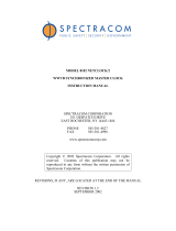
2.3 Typical Installation
Figure 2-1 illustrates a typical TimeGuard installation. The TimeGuard selects and outputs time
data received from the primary or backup time-servers. The selected time data outputs are
used to synchronize various devices requiring accurate time.
Figure 2-1: Typical TimeGuard Installation
Figure 2-2: Typical TimeGuard Installation
Primary NetCloc
k
Backup NetCloc
k

Spectracom Corporation Model 8145
TimeGuard Instruction Manual
2
-
3
Preparations for Use
This section outlines the set-up procedure for the Model 8145 TimeGuard. The DIP switch
functions described in this section are located inside the unit. Refer to Section 3, Operation, for
a detailed description of DIP switch functions.
2.3.1 Line Voltage Selection
The TimeGuard is factory set for 115 VAC ±15%, 50/60 Hz power line operation. The
instrument may also be operated from a 230 VAC ±15%, 50/60 Hz power line. For 230 VAC
operation, change the voltage selection drum and line fuse as illustrated in Figure 2-2, and as
described below:
1. Remove the line cord (if installed) from the line voltage connector.
2. Open the fuse and selector drum cover with a small flat-bladed screwdriver.
Insert the screwdriver blade into the cover notch and pry.
3. Pull the voltage selection drum from the power connector assembly. Reinsert the
drum so that the desired line voltage appears through the cover cut-out.
4. Pull the fuse block from the power connector assembly. Replace fuse with a 1/8
amp, 250V slow blow fuse for 230 VAC operation.
5. Reinstall the fuse block into the lower fuse compartment. Make certain the arrow
on the fuse block is pointing down.
6. Snap cover door closed.

Model 8145 Spectracom Corporation
TimeGuard Instruction Manual 2-4
Figure 2-3: Line Voltage Selection/Fuse Replacement
2.3.2 Switchover Mode Selection
The front panel AUTO switch configures the TimeGuard to operate in MANUAL or AUTOMATIC
switchover mode. In MANUAL switchover mode, the Primary or Backup Clock may be selected
as the time data source by depressing corresponding CLOCK button. The TimeGuard operates
in the MANUAL mode when the AUTO switch is in the OUT position and the AUTO switch
indicator lamp is off.
Depressing the AUTO switch enables AUTOMATIC failure detection and switchover and causes
the AUTO mode indicator lamp to light. The NetClock time synchronization status and the
presence of the time data outputs are monitored in the AUTOMATIC mode. A loss of time
synchronization to WWVB or GPS or loss of time data signal causes the TimeGuard to select
the Backup NetClock. The TimeGuard automatically reselects the Primary NetClock when the
fault condition is corrected.

Spectracom Corporation Model 8145
TimeGuard Instruction Manual
2
-
5
2.3.3 IRIG Signal Select
NetClock receivers equipped with IRIG output can be configured to output an amplitude
modulated (AM) or pulse width coded (TTL) IRIG B or IRIG E signal. Set the TimeGuard IRIG
detection circuitry to match the type of IRIG signals applied. The TimeGuard is factory set to
detect the presence of amplitude modulated IRIG signals.
Applications using pulse width coded (TTL) IRIG signals require a DIP switch setting change.
Internal DIP switch SW1 sets the threshold level of the IRIG detection circuitry. Refer to Figure
2-3 to assist in locating DIP switch SW1. To select pulse width coded operation, place switch
number 1 and 2 in the TTL (ON) position.
Figure 2-4: DIP Switch Locations
2.3.4 Installations Without IRIG
The TimeGuard is factory set to monitor the presence of the RS-232, RS-485, and the optional
IRIG time data outputs from the NetClock. If any of the time data outputs are not detected, the
TimeGuard will Minor Alarm and extinguish the READY status lamps.
The TimeGuard must be configured to ignore the IRIG signal in installations where the NetClock
receivers are not equipped with IRIG output. To disable the IRIG detection circuits, place
Switch numbers 5 and 7 of DIP Switch SW2 in the OFF position. Refer to Figure 2-3 to locate
DIP Switch SW2.
2.4 Rack Mounting
The TimeGuard installs into an EIA 19-inch rack. The panel height is one rack unit (1.75
inches). The recommended configuration is to install the TimeGuard and the Primary and
Backup NetClock receivers in the same rack. For installations in which minimal rack space is
available, Spectracom offers a side-by-side rack mount kit for the Model 8182 NetClock
receivers. The side-by-side panel height is 3 rack units (5.25 inches). A single mount rack kit is
also available; the panel height is two rack units (3.5 inches).

Model 8145 Spectracom Corporation
TimeGuard Instruction Manual 2-6
2.5 Input Connections
The mating cables for IRIG, Serial Comm, Remote and AC inputs are provided in the ancillary
kit.
Connect the line cord to the TimeGuard AC input module and a properly grounded outlet. A
ground lug is provided for use in installations where electrical codes require an additional safety
ground connection.
Connect the input data cables to the corresponding connectors of the Primary and Backup
NetClock receivers.
NOTE: Installations in which NetClock receivers are not equipped with IRIG output require a
DIP Switch configuration change in the TimeGuard. Refer to Section 2.3.4,
Installations without IRIG, for more information.
2.5.1 Connecting the TimeGuard to TTS Receivers, 9100 Series NetClocks,
and 9200 Series Netclocks
The TimeGuard accepts time data from Spectracom synchronized clocks designated as Primary
and Backup time sources. The WWVB synchronized Model 8182 Netclock/2, GPS
synchronized Model 8183 NetClock/GPS, Model 91xx NetClock, Model 92xx NetClock, and TTS
series receivers are available as time sources. The TimeGuard may utilize the same model
clocks or combination of clocks, i.e., NetClock/GPS as primary and NetClock/2 as backup.
The TimeGuard supports IRIG, Remote RS-485, Serial RS-232 interrogation and once-per-
second time data signals. Fault detection within the TimeGuard allows automatic switchover
between the applied inputs. Unused or unavailable time signals can be disabled within the
TimeGuard to match the master clocks available outputs or application requirements. For
example, the Model 9189 does not have IRIG or RS-232 once-per-second outputs. These
signals must be disabled within the TimeGuard to allow proper operation.
NetClock/2 output connectors match the TimeGuard input connectors. The two products simply
connect together using the cables provided in the TimeGuard ancillary kit. Follow the
installation guidelines published in the TimeGuard Instruction Manual.
The Model 8183 NetClock/GPS, Model 91xx NetClock, Model 92xx NetClock, and TTS series
receivers’ output signals and connectors differ from some of the TimeGuard input connectors.
This difference requires the use of an adapter and set-up configuration to allow operation with
the TimeGuard.
2.5.1.1 Adapter Cable Designations
All required cables and adapters are provided in the TimeGuard ancillary kit. 91xx, 92xx, and
TTS receivers require the use of the 8145-0001-5000 cable adapter assembly. Model 8183
units require the use of the 8145-0000-5000 cable adapter assembly. Refer to
Figure 2-5 for more information.

Spectracom Corporation Model 8145
TimeGuard Instruction Manual
2
-
7
Figure 2-5: TimeGuard Adapter Cable Diagram
2.5.1.2 Serial Comm Connection
Connect one of the supplied DB9 cables between the NetClock/NTP Serial Comm port and the
appropriate (Primary or Backup) TimeGuard Serial Comm port.
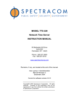
2.5.1.3 Remote Connection
The TimeGuard utilizes DB9 connectors for the Remote Inputs. The TimeGuard monitors the
time synchronization status and the presence of RS-232 and RS-485 once-per-second data
streams applied to the Remote Inputs.
The 91xx, 92xx, and TTS receivers provide RS-485 once-per-second data on a 3-position
terminal strip. Time Synchronization status is communicated by Relay 1 contact closure that is
configured for Major Alarm operation. The connector difference requires the use of an adapter
to connect these signals to the TimeGuard Remote Inputs.
Install the 8145-0001-5000 adapters as described below:
1
2
3
4
5
6
7
1
2
3
1
2
3
4
5
6
7
8
9
1
2
3
4
5
6
7
8
9
U2
U1
U3
P13007
P13003
J03309
Netclock/GPS
Remote
Output
DB9 Male
Serial 2
Netclock/GPS Alarm Output
Major Alarm Common to Major Alarm Normally Open
U4
J03609
DB9 Female
to 050008
Cable to
8145
TimeGuard

Model 8145 Spectracom Corporation
TimeGuard Instruction Manual 2-8
● Insert the 10-position terminal strip from the adapter into the 91xx/TTS receiver Timer/Alarm
Relays connector.
● Insert the 3-position terminal strip from the adapter into the receiver’s RS-485 Remote Port 1
connector.
● Connect one of the supplied DB9 cables between the adapter and the appropriate (Primary
or Backup) Remote Input connector.
2.5.1.4 IRIG Connection
IRIG is available from 9183 and 9283 NetClock/GPS units as well as from TTS240 receivers.
Connect one of the supplied BNC cables between the receiver and the appropriate (Primary or
Backup) TimeGuard IRIG Input port. The TimeGuard can be configured to accept either
Amplitude Modulated (AM) or Pulse-Width-Coded (TTL) IRIG formats. Refer to Installation in
this manual for more information.
If IRIG is not required for the application or if using non-IRIG equipped receivers the
TimeGuard must be configured to disable this input signal. Refer to Section 3 for TimeGuard
configuration information.
2.5.1.5 TimeGuard Configuration
The 8183, 91xx, 92xx, and TTS series receivers do not provide a RS-232 once-per-second time
data stream as found on the NETCLOCK/2 remote port. In addition, some receivers may not be
equipped with an IRIG output. To assure proper operation the TimeGuard must be configured
to match the available time data streams. Internal DIP-switch SW2 is used to select which time
data signals are monitored by the TimeGuard’s fault detection circuitry.
DIP switch SW2 is illustrated in Figure 2-6. Table 2-2 provides the recommended DIP-switch
configuration for use with 91xx, 92xx, and TTS series receivers.
Figure 2-6: DIP Switch SW2
/