FCB Pinnacle

Cornelius FCB Pinnacle Installation guide

  • Hello! I am an AI chatbot trained to assist you with the Cornelius FCB Pinnacle Installation guide. I’ve already reviewed the document and can help you find the information you need or explain it in simple terms. Just ask your questions, and providing more details will help me assist you more effectively!
INSTALLATION INSTRUCTIONS
FCB Pinnacle 2 and 4 Flavor Units
Release Date: March 26, 2007
Publication Number: 629091023INS
Revision Date: March 24, 2014
Revision: C
Visit the Cornelius web site at www.cornelius.com for all your Literature needs.
The products, technical information, and instructions contained in this manual are subject to change without notice.
These instructions are not intended to cover all details or variations of the equipment, nor to provide for every possi
-
ble contingency in the installation, operation or maintenance of this equipment. This manual assumes that the per-
son(s) working on the equipment have been trained and are skilled in working with electrical, plumbing, pneumatic,
and mechanical equipment. It is assumed that appropriate safety precautions are taken and that all local safety and
construction requirements are being met, in addition to the information contained in this manual.
This Product is warranted only as provided in Cornelius’ Commercial Warrant applicable to this Product and is sub-
ject to all of the restrictions and limitations contained in the Commercial Warranty.
Cornelius will not be responsible for any repair, replacement or other service required by or loss or damage resulting
from any of the following occurrences, including but not limited to, (1) other than normal and proper use and normal
service conditions with respect to the Product, (2) improper voltage, (3) inadequate wiring, (4) abuse, (5) accident,
(6) alteration, (7) misuse, (8) neglect, (9) unauthorized repair or the failure to utilize suitably qualified and trained per
-
sons to perform service and/or repair of the Product, (10) improper cleaning, (11) failure to follow installation, oper-
ating, cleaning or maintenance instructions, (12) use of “non-authorized” parts (i.e., parts that are not 100%
compatible with the Product) which use voids the entire warranty, (13) Product parts in contact with water or the
product dispensed which are adversely impacted by changes in liquid scale or chemical composition.
Contact Information:
To inquire about current revisions of this and other documentation or for assistance with any Cornelius product con-
tact:
www.cornelius-usa.com
800-238-3600
Trademarks and Copyrights:
This document contains proprietary information and it may not be reproduced in any way without permission from
Cornelius.
This document contains the original instructions for the unit described.
CORNELIUS INC
101 Regency Drive
Glendale Heights, IL
Tel: + 1 800-238-3600
Printed in U.S.A.
Pinnacle Hot Gas Valve Replacement Installation Instructions
© 2007-2014, Cornelius Inc. - 1 - Publication Number: 629091023INS
SAFETY INSTRUCTIONS
SAFETY
!
WARNING:
Before starting installation, read and understand all safety label and warnings on the machine. Also review and
understand all safety instructions in the owners, installation and service manuals.
Failure to comply could result in serious injury, death or damage to the equipment.
QUALIFIED SERVICE PERSONNEL
!
WARNING:
Only trained and certified electrical, plumbing and refrigeration technicians should service this unit.
All wiring and plumbing must conform to national and local codes. Failure to comply could
result in serious injury, death or equipment damage.
SAFETY PRECAUTIONS
This unit has been specifically designed to provide protection against personal injury. To ensure continued
protection observe the following:
!
WARNING:
Disconnect power to the unit before servicing. Follow all lock out/tag out procedures established by the user. Verify all
power is off to the unit before performing any work.
Failure to comply could result in serious injury, death or damage to the equipment.
CAUTION:
!
Always be sure to keep area around the unit clean and free of clutter.
Failure to keep this area clean may result in injury or equipment damage.
Pinnacle Hot Gas Valve Replacement Installation Instructions
Publication Number: 629091023INS - 2 - © 2007-2014, Cornelius Inc.
INSTALLATION INSTRUCTIONS
HOT GAS VALVE REPLACEMENT PROCEDURE
These instructions are intended to cover Pinnacle units with a serial number beginning with 62 only. This hot gas
valve kit and instructions are designed for the refrigeration piping specific to the units starting with the serial
number 62.
If you have a Pinnacle with a serial number beginning with 56, please order kit number 629092235 for the kit and
installation instructions (629092235INS) designed for your unit.
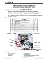
Parts List
Tools Required
1. 1 - Screwdriver
2. 1 - Tape Measure
3. 1 - Sharp Edge Tool (for insulation removal)
4. 1 - Imp Tubing Cutter
5. 1 - Brazing Torch
6. 2 - Brazing Rod
Figure 1.
Part No. Description Qty.
620608516 Valve Assembly 1
620203604 Towels 6
620608601 Filter Drier 1
620407990 90° Elbows for drier installation 2
50326 Foam Tape 48”
Pinnacle Hot Gas Valve Replacement Installation Instructions
© 2007-2014, Cornelius Inc. - 3 - Publication Number: 629091023INS
Replacement Instructions
1. Remove the top and rear panels.
Figure 2.
2. Remove the two screws from the top of the
electrical box and swing it out to the side.
Secure the electrical box in the open position
with tape.
3. Attach gauges and initiate refrigerant removal.
4. While charge is being removed perform following procedure:
A. Remove wire connectors to pulse valve, 2 plugs. Set the wires aside.
B. Remove wire connectors to hot gas valves, 2 plugs. Set the wires aside.
Step2
Figure 3.
Step1
Pinnacle Hot Gas Valve Replacement Installation Instructions
Publication Number: 629091023INS - 4 - © 2007-2014, Cornelius Inc.
C. Remove wire connectors to compressor terminals (run, start, and common). Set red, black, and
white wires away from hot gas valves.
Figure 4.
D. Remove insulation on bottom of pulse
valves, 2 each.
E. Remove barrel inlet thermistors, 2 each,
from pulse valve outlets.
Figure 5.
F. Remove insulation on bottom of hot gas
valves, 2 each.
Figure 6.
Step1
Step2
13/8”
Pinnacle Hot Gas Valve Replacement Installation Instructions
© 2007-2014, Cornelius Inc. - 5 - Publication Number: 629091023INS
8. Carefully make the tube-cut locations on the hot gas valve outlets at 1-3/8” from the backside of the copper
T, as shown. Cut hot gas valve inlets, 2 each, with imp tubing cutter.
9. Remove insulation on hot gas valve inlet line (if present).
Figure 8.
5. After the charge is removed and pressure has equalized, remove Schrader valve cores (2 each).
6. Use the 90° copper elbow, included in the kit, to carefully mark the tube-cut locations on the drier inlet
and outlet.
7. Use tubing cutter to cut-out filter/drier. Cap both tube openings.
Step 1
Step 2
Figure 7.
Pinnacle Hot Gas Valve Replacement Installation Instructions
Publication Number: 629091023INS - 6 - © 2007-2014, Cornelius Inc.
10. Carefully mark the tube-cut locations on the hot gas valve inlet at 1-5/8” up from the copper hot gas
header, as shown Cut hot gas valve inlet line with imp tubing cutter.
Figure 9.
11. Remove hot gas valve assembly.
Step1
Step 2
Figure 10.
15/8
Pinnacle Hot Gas Valve Replacement Installation Instructions
© 2007-2014, Cornelius Inc. - 7 - Publication Number: 629091023INS
12. Cover area behind and under braze area with wet legs.
Figure 11.
13. Install hot gas valve assembly provided (three braze fittings).
14. Wrap hot gas and pulse valves with wet rags.
Step 1
Step 2
Figure 12.
Pinnacle Hot Gas Valve Replacement Installation Instructions
Publication Number: 629091023INS - 8 - © 2007-2014, Cornelius Inc.
15. Push all wire harnesses aside to prevent burn damage.
Figure 13.
16. Braze the 3 solder joints.
Figure 14.
17. Install the new filter/drier using the two braze fittings with the 90° copper elbows, supplied in the kit.
Pinnacle Hot Gas Valve Replacement Installation Instructions
© 2007-2014, Cornelius Inc. - 9 - Publication Number: 629091023INS
IMPORTANT: Allow no more than 30 minutes between removing drier caps and beginning
evacuation is step 20.
Figure 15.
18. Re-install Schrader valve cores.
19. Pressurize refrigeration system and check (listen) for leaks at the 5 new solder joints.
20. Install vacuum pump and begin evacuation. Perform the following functions while the system is evacuating.
A. Remove all wet rags and debris from inside unit.
B. Re-install solenoid coils on pulse valves and hot gas valves.
C. Re-attached harness plugs to both hot gas valves and pulse valves.
NOTE: Check to be sure the harnesses are connected to the correct components.
D. Re-attached run, start, and common wires to compressor terminal block. Re-install compressor
terminal block cover using strap.
E. Re-install thermistors on both pulse valves.
F. Seal-up both thermistors and insulate them.
G. Install insulation wrap around the pulse valve and hot gas valve outlets.
21. Evaluate micron gauge to verify leak free system.
22. Charge unit to nameplate charge.
23. Remove gauges and rotate control box back into position, re-install 2 screws.
24. Repeat steps 1 and 2 in reverse order to complete the installation.
Pinnacle Hot Gas Valve Replacement Installation Instructions
Publication Number: 629091023INS - 10 - © 2007-2014, Cornelius Inc.
Cornelius Inc.
www.cornelius.com
/