Page is loading ...

Manual
Version- E230620

Manual
D-LINE / D-SAT
Page 2
Important Information
General
Before using your ALGE-TIMING device read the complete manual carefully. It is part of the device and
contains important information about installation, safety and its intended use. This manual cannot cover
all conceivable applications. For further information or in case of problems that are mentioned not at all
or not sufficiently detailed, please contact your ALGE-TIMING representative. You can find contact de-
tails on our homepage www.alge-timing.com
Safety
Apart from the information of this manual all general safety and accident prevention regulations of the
legislator must be taken into account.
The device must only be used by trained persons. The setting-up and installation must only be executed
according to the manufacturer’s data.
Intended Use
The device must only be used for its intended applications. Technical modifications and any misuse are
prohibited because of the risks involved! ALGE-TIMING is not liable for damages that are caused by
improper use or incorrect operation.
Power supply
The stated voltage on the type plate must correspond to voltage of the power source. Check all connec-
tions and plugs before usage. Damaged connection wires must be replaced immediately by an author-
ized electrician. The device must only be connected to an electric supply that has been installed by an
electrician according to IEC 60364-1. Never touch the mains plug with wet hands! Never touch live parts!
Cleaning
Please clean the outside of the device only with a smooth cloth. Detergents can cause damage. Never
submerge in water, never open or clean with wet cloth. The cleaning must not be carried out by hose or
high-pressure (risk of short circuits or other damage).
Liability Limitations
All technical information, data and information for installation and operation correspond to the latest
status at time of printing and are made in all conscience considering our past experience and knowledge.
Information, pictures and description do not entitle to base any claims. The manufacturer is not liable
for damage due to failure to observe the manual, improper use, incorrect repairs, technical modifications,
use of unauthorized spare parts. Translations are made in all conscience. We assume no liability for
translation mistakes, even if the translation is carried out by us or on our behalf.
Disposal
If a label is placed on the device showing a crossed out dustbin on wheels (see drawing), the
European directive 2002/96/EG applies for this device.
Please get informed about the applicable regulations for separate collection of electrical and
electronical waste in your country and do not dispose of the old devices as household waste.
Correct disposal of old equipment protects the environment and humans against negative
consequences!
Copyright by ALGE-TIMING GmbH
All rights reserved. Any duplication, either in full or in part, requires the prior written consent of the
copyright holder.

Manual
D-LINE / D-SAT
Page 3
Declaration of Conformity
We declare that the following products comply with the requirements of the listed standards.
Parts that we use in the product are CE certificated by the manufacturers and ALGE-TIMING
GmbH does not change them.
We, ALGE-TIMING GmbH
Rotkreuzstrasse 39
A-6890 Lustenau
Declare under our sole responsibility, that the display board:
D-LINE
and its models of the series 57, 100, 150, 250, 300, 450, 600, 1000, 1500, SDA1 pro-
duced from 01.01.2005 and later
is in conformity with the following standard(s) or other normative documents(s):
Safety: IEC 60950:1999 / EN 60950:2000
EN 60335-1:2002 + A11:2004 + A1:2004 + A12:2006 + A2:2006
EMC: EN55022:2006+A1:2007
EN55024:1998+A1:2001+A2:2003
EN61000 3-2:2006
EN61000 3-3:1995+A1:2001+A2:2005
Additional Information:
The product herewith complies with the requirements of the Low Voltage Directive 73/23/EEC,
also the EMC Directive 2004/108EG and accordingly carries the CE-marking.
Lustenau, 30.11.2010 ALGE-TIMING GmbH
Albert Vetter
(General Manager)

Manual
D-LINE / D-SAT
Page 4
Table of Contents
1 Connections .................................................................................................................... 6
1.1 D-LINE .......................................................................................................................... 6
1.2 D-SAT ........................................................................................................................... 6
2 Operation ....................................................................................................................... 7
2.1 Change of Display Mode ................................................................................................. 7
2.2 Standard Settings .......................................................................................................... 7
2.3 Parameter List ............................................................................................................... 7
2.3.1 Set Time of Day Hours [P0] ....................................................................................................... 7
2.3.2 Set Time of Day Minutes [P1] .................................................................................................... 7
2.3.3 Set Time of Day Seconds [P2] .................................................................................................... 7
2.3.4 Set the Day of the Date [P3] ...................................................................................................... 7
2.3.5 Set the Month of the Date [P4] ................................................................................................. 7
2.3.6 Set the Year of the Date [P5] ..................................................................................................... 7
2.3.7 Display Time for Time of Day [P6] .............................................................................................. 7
2.3.8 Display Time for Date [P7] ........................................................................................................ 7
2.3.9 Display Time for Temperature [P8] ............................................................................................ 8
2.3.10 Calibration of Temperature....................................................................................................... 8
2.3.11 Calibration of Water Temperature ............................................................................................ 8
2.3.12 Display Time for Relative Humidity ............................................................................................ 8
2.3.13 Calibration of Relative Humidity ................................................................................................ 8
2.3.14 GPS Offset Hours to UTC........................................................................................................... 8
2.3.15 GPS Offset Minutes UTC ........................................................................................................... 8
2.3.16 Area Settings for Temperature and Time .................................................................................... 8
2.3.17 Brightness [A0] (b) ................................................................................................................... 9
2.3.18 Display Mode and Serial Interface [A1], (S) ............................................................................... 10
2.3.19 Time-Out Time-Temperature-Date [A2] ................................................................................... 11
2.3.20 Address Setting [A3] (A).......................................................................................................... 11
2.4 Extended Data Mode ................................................................................................... 11
2.4.1 Timer S4, Points Show Jumping ........................................................................................................ 11
2.4.2 TdC8001, Points Show Jumping ........................................................................................................ 13
2.4.3 8-digit Display Board for Swimming .................................................................................................. 14
2.4.4 Track&Field Concentration clock, wind and performance.................................................................... 15
2.4.5 Fixed Comma or Colon .................................................................................................................... 15
3 Special Functions .......................................................................................................... 16
3.1 Stopwatch, Countdown and Counter .............................................................................. 16
3.1.1 Stopwatch (from Version 4.5)........................................................................................................... 16
3.1.2 Countdown (from Version 4.5) ......................................................................................................... 16
3.1.3 Counter (from Version 4.5) .............................................................................................................. 17
3.1.4 Stopwatch-Countdown (Version 4.3.and 4.4) ..................................................................................... 17
3.1.5 Counter (Version 4.3.and 4.4) .......................................................................................................... 18
4 Technical Data .............................................................................................................. 19

Manual
D-LINE / D-SAT
Page 5
4.1 Dimensions ................................................................................................................. 19
4.2 Power Supply .............................................................................................................. 20
4.2.1 Supply from Mains .......................................................................................................................... 20
4.2.2 Supply from External Battery ........................................................................................................... 20
4.2.3 DCF Antenna (D-SAT)....................................................................................................................... 20
4.3 Interface Formats ........................................................................................................ 21
4.3.1 Serial Interface: .............................................................................................................................. 21
4.3.2 Ethernet......................................................................................................................................... 23

Manual
D-LINE / D-SAT
Page 6
right side
left side
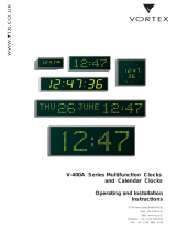
1 Connections
1.1 D-LINE
1.2 D-SAT
The D-SAT has all connections on feeder clamps.
manual button for setting display
modes
Amphenol plug:
1
+10 bis 12 V
2
ground
3
data out
E
data in
connection for push button
(stop watch, count down, and
counter function)
data in and ground
100
- 240 V, 50 -
60 Hz
1.0 A fuse
RS 485 A and B

Manual
D-LINE / D-SAT
Page 7
2 Operation
2.1 Change of Display Mode
You can change the display mode with the manual button at the display or with the PC software
and the cable 145-05.
To change the parameters with the manual button, press the button until the first parameter
appears on the display. If you wait for a few seconds the value of the parameter starts blinking.
You can now change the parameter or value that is blinking. To save the changes you need
to pass through all parameters until leaving the menu.
2.2 Standard Settings
The D-LINE display boards are delivered with a standard setting optimized for timing purposes.
To reset the factory settings, keep the internal button pressed until the software version ap-
pears on the display.
ATTENTION: Only display boards built after 2005-06 are equipped with this function.
2.3 Parameter List
The parameter list is designed in such a way that the user recognizes the required parameter
by its name.
ATTENTION: Older D-LINE models have different parameter names. These old parameter
names are stated in square brackets [xx]. Some of the settings are identical and some are not
available at all with older models.
ATTENTION: 3-digit displays are not equipped with many of the below stated parameters or
the parameters have to be displayed differently due to lack of space. The parameter names
for 3-digit displays are stated in round brackets. (xx)
2.3.1 Set Time of Day Hours [P0]
2.3.2 Set Time of Day Minutes [P1]
2.3.3 Set Time of Day Seconds [P2]
2.3.4 Set the Day of the Date [P3]
2.3.5 Set the Month of the Date [P4]
2.3.6 Set the Year of the Date [P5]
2.3.7 Display Time for Time of Day [P6]
Duration in seconds during which the time of day is displayed; parameter ‘0’ = no time of day
displayed
2.3.8 Display Time for Date [P7]
Duration in seconds during which the date is displayed; parameter ‘0’ = no date displayed

Manual
D-LINE / D-SAT
Page 8
2.3.9 Display Time for Temperature [P8]
Duration in seconds during which the temperature is displayed; only available with temperature
sensor
2.3.10 Calibration of Temperature
This parameter is only displayed if the temperature is on (e.g. tt 05). The shown temperature
can be adjusted by up to +/-9 degrees.
2.3.11 Calibration of Water Temperature
This parameter is only displayed if the temperature is on (e.g. tt 05). The shown temperature
can be adjusted by up to +/-9 degrees.
2.3.12 Display Time for Relative Humidity
Duration in seconds during which the relative humidity is displayed; only available with sensor
2.3.13 Calibration of Relative Humidity
This parameter is only displayed if the sensor adjustment is on (e.g. tH 05). The shown relative
humidity can be adjusted by up to +/-9 percent.
2.3.14 GPS Offset Hours to UTC
This parameter is only displayed if there is a connection for a GPS. With this parameter you
can adjust the offset to UTC in hours.
2.3.15 GPS Offset Minutes UTC
This parameter is only displayed if there is a connection for a GPS. With this parameter you
can adjust the offset to UTC in minutes.
2.3.16 Area Settings for Temperature and Time
This area parameter is for setting the display mode for time and temperature. The first digit in
the setting is for automatically changing the clock to daylight saving time, the second one is
for the display mode. The following settings are possible:
2.3.16.1 Daylight Saving Time Switching [P9]
The first digit of the area setting is responsible for internally changing the clock to daylight
saving time and standard time.
2.3.16.1.1 Daylight Saving Time Switching [0x]
No internal changing, used for DCF-controlled clocks
2.3.16.1.2 European Daylight Saving Time [1x]
Change to daylight saving time for Europe, used with internal clock, GPS and NTP-synchroni-
zation
2.3.16.1.3 USA Daylight Saving Time [2x]
Change to daylight saving time for USA, used with internal clock, GPS and NTP-synchroniza-
tion.
2.3.16.1.4 Australian Daylight Saving Time [3x]
Change to daylight saving time for Australia, used with internal clock, GPS and NTP-synchro-
nization.

Manual
D-LINE / D-SAT
Page 9
2.3.16.2 Time and Temperature Setting
The second digit of the area setting is used for the display mode of the time and temperature;
12 h, 24 h, Celsius or Fahrenheit.
2.3.16.2.1 Celsius and 24 h [x0]
Time in 24 h mode and temperature in Celsius
2.3.16.2.2 Celsius and 12 h [x1]
Time in 12 h mode and temperature in Celsius
2.3.16.2.3 Fahrenheit and 24 h [x2]
Time in 24 h mode and temperature in Fahrenheit
2.3.16.2.4 Fahrenheit and 12 h
Time in 12 h mode and temperature in Fahrenheit
2.3.16.2.5 Celsius and 24 h
Time in 24 h mode and temperature in Celsius but on 6-digit D-LINE time is centred and without
running seconds.
2.3.16.2.6 Celsius and 12 h
Time in 12h mode and temperature in Celsius, but on 6-digit D-LINE time is centred and without
running seconds.
2.3.16.2.7 Fahrenheit and 24 h
Time in 24 h mode and temperature in Fahrenheit but on 6-digit D-LINE time is centred and
without running seconds.
2.3.16.2.8 Fahrenheit and 12 h
Time in 12 h mode and temperature in Fahrenheit but on 6-digit D-LINE time is centred and
without running seconds.
2.3.17 Brightness [A0] (b)
With this parameter brightness settings and effects can be set. The first digit is for the appear-
ance, the second one for the brightness.
2.3.17.1 First digit of setting
The first digit defines the type of changing between time and temperature. Fade-in changes
over with brightness effect from time to temperature.
2.3.17.1.1 Fade-in off
Fading is not activated.
2.3.17.1.2 Fade-in on
Fading is activated.
2.3.17.2 Second Digit of Setting
This setting defines the brightness mode of the display.
2.3.17.2.1 Manual setting
The second digit of the brightness settings can be adjusted manually from 0 to 9. Value 0 is
minimum brightness and value 9 maximum. This adjustment can also be affected by using the
menu of TdC8001 or TIMY.
2.3.17.2.2 Time of Day Dependent Brightness [x3]
Brightness is set automatically, depending on the time of day.

Manual
D-LINE / D-SAT
Page 10
2.3.17.2.3 Light Sensor Dependent Brightness [x4]
With this setting, the brightness depends on the light sensor. If no light sensor is connected,
maximum brightness is set.
2.3.18 Display Mode and Serial Interface [A1], (S)
This setting is for the interface parameters. The first digit in the setting is for the display mode,
the second one for the interface speed.
2.3.18.1 Display Mode
Here, the different display modes for your display board can be adjusted.
2.3.18.1.1 hh:mm:ss [0x] (1sec)
2.3.18.1.2 h:mm:ss.z (1/10sec) and speed with 1/10
2.3.18.1.3 mm:ss:zh [1x] (1/100sec)
2.3.18.1.4 m:ss.zht (1/1000sec)
2.3.18.1.5 Bib, Rank [2x]
2.3.18.1.6 extended Mode [4x]
This advanced mode serves for configuring the complete display yourself. You can define
which byte is shown at which position on the display board.
If the serial setting is in this mode, you have some more parameters for adjusting the mode:
,,,,… [A5, A6,…B0, B1,…]. For a detailed description how to adjust these
parameters, see point 2.4
2.3.18.1.7 Slave/Master Communication (RS485 or RS232, master=TX,
slave=RX) [5x] and also for GPS operation (set 4800 baud = Sen4)
2.3.18.1.8 mm:ss.zh [1x] (1/100sec.)
Identical to SEh but in the stopwatch mode the time is shown in seconds: 60 seconds instead
of 1:00 minute (also see page 17).
2.3.18.1.9 Game Terminal CKN Playing Time (mm:ss, central) must be 9600
Baud.
D-LINE is connected with RS232 to the CKN terminal (Pin5=GND, PIN2=data).
Works from CKN software 11-2006 (wireless protocol) – wired no longer exists.
2.3.18.1.10 Freeze Time of Day [3x]
With this function the time of day can be frozen with a manual button on the green/black ba-
nana socket for the duration of the time-out time. The time of day continues internally.

Manual
D-LINE / D-SAT
Page 11
2.3.18.2 Transfer Speed/Protocol
The second digit of the setting is responsible for the transfer speed of the serial interface.
2.3.18.2.1 2400, N, 8, 1 ALGE-Timing standard [x0]
2.3.18.2.2 4800, N, 8, 1 ALGE-TIMING [x1]
2.3.18.2.3 9600, N8, 1 ALGE-TIMING [x2]
2.3.18.2.4 19200, N, 8, 1 ALGE-TIMING [x3]
2.3.18.2.5 special Format
2.3.18.2.6 old devices like the S3, Selftimer SF2 [x4]
2.3.18.2.7 countdown mode see point 3.1.2 Countdown (from Version 4.5)
2.3.19 Time-Out Time-Temperature-Date [A2]
This setting defines the time after which the display board switches from serial display mode
back to time-temp mode. If it is set to 00, the parameters described from point 2.3.1 to point
2.3.16 are no longer visible. The display modes for time of day, temperature and date are thus
deactivated. Up to version 3.7 the specifications are in seconds and from version 3.8 the value
is multiplied by 10, so an adjustment of 24 is 240 seconds.
2.3.20 Address Setting [A3] (A)
To use more than one D-LINE on an addressed protocol, you have to define the addresses of
every single display board. Normally, the first line is address 1 , second line address
2 , etc.
Depending on the sport, this setting can be important to display the serial data of your timing
device correctly. Please also refer to the manual of the corresponding timing device. The sport
specific instructions for controlling the display board can be found there.
2.4 Extended Data Mode
In this mode, one byte of the data string can be assigned to each digit. For example, it is
possible to display on a 6-digit display board the bib on the first 2 digits and the time in m:ss
on the last 3 digits. For some sports like equestrian (with Timer S4), you have to program the
display for the presentation of the points in this mode. It is not possible to show datasets of
differently addressed data strings.
2.4.1 Timer S4, Points Show Jumping
Below, a configuration of a 6-digit display for showing the points by Timer S4 (equestrian) in
the middle of the display is described.
The data package of the Timer S4 looks as follows:
1
2
3
4
5
6
7
8
9
10
11
12
13
14
15
16
17
18
19
20
21
22
23
24
PZ
PE
.
H
H
:
M
M
:
S
S
.
z
Pz
Pe
CR
PZ
PE
H
H
:
M
M
:
S
S
.
z
h
t
Pz
Pe
CR
The parameters have to be set as follows:

Manual
D-LINE / D-SAT
Page 12
2.4.1.1 Display Board D-LINE for Points
Extended protocol, 2400 bps [A1-40] (S-E2)
Device address 00 [A3 00] (A-00)
First digit is always inactive [A5-00]
Dot or colon after first digit is always inactive [A6-00]
Second digit is to display points PZ [A7-01]
Dot or colon after second digit is always inactive [A8-00]
Third digit is to display points PE [A9-02]
Show the dot which is sent after the full second [B0-17]
Fourth digit is to show points (PZ) [B1-21]
Dot or colon after fourth digit is always inactive [B2-00]
Fifth digit is to show points [B3-22]
Dot or colon after fifth digit is always inactive [B4-00]
Sixth digit is always inactive [B5-00]
2.4.1.2 Display Board D-LINE for Time
Extended protocol, 2400 bps [A1-40] (S-E2)
Device address 00 [A3 00] (A-00)
First digit shows thousands of seconds [A5-09]
Dot or colon after first digit is always inactive [A6-00]
Second digit shows hundreds of seconds [A7-10]
Dot or colon after second digit is always inactive [A8-00]
Third digit shows tenth seconds [A9-12]
Dot or colon after third digit is always inactive [B0-00]
Fourth digit shows units seconds [B1-13]
Fourth digit shows a point (PZ) [B2-21]
First digit shows 1/10th seconds [B3-15]
Dot or colon after fifth digit is always inactive [B4-00]
Sixth digit shows 1/100th seconds [B5-16]

Manual
D-LINE / D-SAT
Page 13
2.4.2 TdC8001, Points Show Jumping
Following, the configuration of a 6-digit display for showing the points by TdC8001 (equestrian)
in the middle of the display is described.
The parameters have to be set as follows:
Extended protocol, 2400 bps [A1-40] (S-E2)
Device address 00 [A3 00] (A-00)
First digit is always inactive [A5-00]
Dot or colon after first digit is always inactive [A6-00]
Second digit is to display points (PZ) [A7-02]
Dot or colon after second digit is always inactive [A8-00]
Third digit is to display points (PZ) [A9-02]
Shows the dot which is sent after the full second [B0-17]
Fourth digit is to show points (PZ) [B1-21]
Dot or colon after fourth digit is always inactive [B2-00]
Fifth digit is to show points [B3-22]
Dot or colon after fifth digit is always inactive [B4-00]
Sixth digit is always inactive [B5-00]
The other two display boards are to be adjusted as shown below:
Display Board Time:
Display Board Bib - Rank:

Manual
D-LINE / D-SAT
Page 14
2.4.3 8-digit Display Board for Swimming
Following, the configuration of an 8-digit display board to show rank, lane and time is de-
scribed. This display board for swimming has a special layout with an empty space between
first and second and between second and third digit.
The parameters have to be set as follows:
extended Protocol, 2400 bps [A1-40]
device address 01 [A3 01], for TM-SWIM
device address 00 [A3 00], for Timy Tracktimer
first digit shows the rank [A5-11]
point or colon after first digit is always inactive [A6-00]
second digit shows the lane [A7-21]
point or colon after second digit is always inactive [A8-00]
third digit shows the minute tens [A9-13]
point or colon after third digit is always inactive [B0-00]
fourth digit shows the minutes [B1-14]
point or colon after fourth digit is active [B2-15]
fifth digit shows the second tens [B3-16]
point or colon after fifth digit is always inactive [B4-00]
sixth digit shows the seconds [B5-17]
seventh digit shows the tenth of a second [B6-19]
point or colon after seventh digit is always inactive [B7-00]
eighth digit shows the hundredth of a second [B8-19]

Manual
D-LINE / D-SAT
Page 15
2.4.4 Track&Field Concentration clock, wind and performance
For Track&Field you can use 3-5 digit D-LINE displays to show the concentration time, the
Windspeed and the performance on the same display
2.4.4.1 3-digit D-LINE
Settings:
Extended protocol, 2400 bps
Device address 03
First digit Byte 13
First comma Byte 14
Second digit Byte 15
Second comma Byte 16
Third digit Byte 17
2.4.4.2 4 digit D-LINE
Settings:
Extended protocol, 2400 bps
Device address 03
First digit Byte 11
First comma Byte 12
Second digit Byte 13
Second comma Byte 14
Third digit Byte 15
Third comma Byte 16
Fourth digit Byte 17
2.4.5 Fixed Comma or Colon
Comma or colon may not be included in the protocol of some older ALGE-TIMING devices.
They can be permanently programmed on the D-LINE.
Comma 98
Colon 99

Manual
D-LINE / D-SAT
Page 16
3 Special Functions
D-LINE display boards can be used as stand-alone stopwatch, countdown clock or counter.
3.1 Stopwatch, Countdown and Counter
To use one of these modes, please to connect a manual button 023-xx at the green and red
banana socket of the D-LINE. By pressing the manual button, the mode is started. For setting
the different modes change the parameter [A1] as described below.
3.1.1 Stopwatch (from Version 4.5)
Starting with version 4.5 we offer a stopwatch function that allows inputting a time from which
the stopwatch starts to run. The delay time of the stopwatch is 1 second; i. e. after each impulse
no further impulse can be triggered for the period of one second (to avoid incorrect photocell
impulses). The parameters are used to set different formats for the stopwatch.
Stopwatch format: hh:mm:ss (hours, minutes, seconds)
Stopwatch format: mm:ss:zh (minutes, seconds, 1/100)
Stopwatch format: ssss:zh (seconds mode with 1/100)
The stopwatch can be started from zero (standard) or any other time that is set. For setting
this time use the push button 023-xx and press it for about 10 seconds until the first digit starts
blinking. If the button continues to be pressed, the blinking setting is saved and the cursor
moves to the next digit. In case this digit is already set correctly, continue to press the button
until in the end the start time is displayed without blinking. Pressing the manual button again
starts the stopwatch.
The stopwatch can be stopped or re-started any time by pressing (intermediate or end time).
If the button is pressed for about 5 seconds the display is reset to zero or after 10 seconds the
time can be reset as required.
3.1.2 Countdown (from Version 4.5)
Starting with version 4.5 we offer a countdown function that allows setting the countdown time.
The parameters are used to set different formats for the countdown.
Countdown format: hh:mm:ss (hours, minutes, seconds)
Countdown format: mm:ss:zh (minutes, seconds, 1/100)
Countdown format: ssss:zh (seconds mode with 1/100)
The standard start time for the countdown is one minute. For setting this time use the push
button 023-xx and press it for about 10 seconds until the first digit starts blinking. If the button
continues to be pressed, the blinking setting is saved and the cursor moves to the next digit.
In case this digit is already set correctly, continue to press the button until in the end the start
time is displayed without blinking. Pressing the manual button again starts the countdown.
The countdown can be stopped or re-started any time by pressing (time-out). If the button is
pressed for about 5 seconds the display is reset to zero or after 10 seconds the time can be
reset as required.

Manual
D-LINE / D-SAT
Page 17
3.1.3 Counter (from Version 4.5)
Starting with version 4.5 we offer a counter function that allows setting any number you like
and count up or down from this number with each button push (manual button 023-xx at green
and black banana socket).
Count up
Count down
Switch on the counter mode. Depending on the direction of counting, the push button has
different functions. Pressing the button for about 2 seconds counts in the opposite direction. If
the first digit of the display blinks you entered the mode for setting the starting number. If the
button continues to be pressed, the blinking setting is saved and the cursor moves to the next
digit. In case this digit is already set correctly, continue to press the button until in the end the
starting number is displayed without blinking. Pressing the manual button again counts one
down. In case the button is pressed for about 2 seconds it counts one up. If pressed for about
10 seconds the display is reset to the initial value.
3.1.4 Stopwatch-Countdown (Version 4.3.and 4.4)
This function is available from version 4.3 with fixed start and stop delay time of 4 seconds to
eliminate incorrect photocell impulses. Switching between stopwatch and countdown is af-
fected by continued pressing of the manual button for about 20 seconds. Displaying 00:00.00
indicates the stopwatch mode, blinking of the first digit the countdown mode. If the button con-
tinues to be pressed, the blinking setting is saved and the cursor moves to the next digit. In
case this digit is already set correctly, continue to press the button until in the end the starting
value is displayed without blinking. Pressing the button again starts the countdown. If pressed
for about 10 seconds the display is reset to the initial value.
3.1.4.1 hh:mm:ss [A1-0x]
Time format for stopwatch and countdown
3.1.4.2 mm:ss:zh [A1-1x]
Time format for stopwatch and countdown
3.1.4.3 ssss:zh
Time format for stopwatch and countdown in second’s mode; for driving (equestrian) or other
sports where time is shown 60 seconds instead of 1:00 minutes; available from version 4.3.

Manual
D-LINE / D-SAT
Page 18
3.1.5 Counter (Version 4.3.and 4.4)
Switching between counting up and counting down is adjusted by continuously pressing the
manual button for about 20 seconds. Display of 0 indicates the count up mode, first digit blink-
ing the countdown mode.
3.1.5.1 Counter
This parameter enables the counter mode. Depending on the counting direction, the function
of the manual button is different. Pressing shortly the button counts up (down) and continued
pressing for about 2 seconds counts down (up).
3.1.5.2 Adjusting the start value
If the first digit of the display blinks you entered the mode for setting the start value. Keeping
the button pressed for a while, the blinking value is saved and the cursor moves to the next
digit. In case this digit is set correctly, keep the button pressed until in the end the start value
is shown without blinking. Pressing the button again counts down by one. If the button is
pressed for 2 seconds, it counts up. Continue to press for as long as 10 seconds resets the
display to the start value.

Manual
D-LINE / D-SAT
Page 19
4 Technical Data
4.1 Dimensions
Type
Number
of digits
Figure Height
A [mm]
Width W
[mm]
Hight H
[mm]
Depth
[mm]
Suspension
Brackets L
[mm]
Bottom
Brackets
Middle
Brackets
Max. Reading
Distance [m]
Power Input
[W]
D-LINE57-I-3-E1
3
57
400
130
60
100
no
no
25
6
D-LINE57-I-4-E0
4
57
400
130
60
100
no
no
25
8
D-LINE57-I-6-E0
6
57
500
130
60
150
no
no
25
13
D-LINE100-I-4-E0
4
100
650
180
80
100
no
no
50
8
D-LINE100-I-6-E0
6
100
800
180
80
150
yes
no
50
13
D-LINE80-O-3-E0
3
80
450
150
60
100
no
no
40
6
D-LINE80-O-4-E0
4
80
450
150
60
100
no
no
40
8
D-LINE80-O-6-E0
6
80
600
150
60
150
no
no
40
13
D-LINE150-O-3-E0
3
150
600
250
60
150
yes
no
75
6
D-LINE150-O-4-E0
4
150
730
250
60
150
yes
no
75
9
D-LINE150-O-5-E1
5
150
956
250
60
200
yes
no
75
11
D-LINE150-O-6-E0
6
150
956
250
60
200
yes
no
75
14
D-LINE250-O-3-E0
3
250
850
350
60
200
yes
no
125
17
D-LINE250-O-4-E0
4
250
1100
350
80
200
yes
no
125
22
D-LINE250-O-5-E1
5
250
1493
350
60
200
yes
no
125
28
D-LINE250-O-6-E0
6
250
1493
350
60
200
yes
no
125
34
D-LINE450-O-4-E0
4
450
1900
600
80
200
yes
no
225
58
D-LINE450-O-6-E0
6
450
2490
600
80
200
yes
yes
225
88
D-LINE600-O-4-E0
4
600
2490
800
70
200
yes
yes
300
87
D-LINE600-O-6-E0
6
600
3400
800
70
200
yes
yes
300
133
D-LINE800-O-4-E0
4
800
3300
1000
70
200
yes
yes
400
120
D-LINE800-O-6-E0
6
800
4800
1000
70
200
yes
yes
400
180
D-LINE1000-O-4-E0
4
1000
3900
1400
70
200
yes
yes
500
180
D-LINE1000-O-6-E0
6
1000
5700
1400
70
200
yes
yes
500
270
D-LINE1500-O-4-E0
4
1500
5800
2000
70
200
yes
yes
750
340
D-LINE1500-O-6-E0
6
1500
8500
2000
70
200
yes
yes
750
510

Manual
D-LINE / D-SAT
Page 20
4.2 Power Supply
4.2.1 Supply from Mains
Display Board up to 250 cm Figure Height:
100 – 240VAC / 50-60 Hz, automatic switching
Display Board with a Figure Height of 450 cm or Higher:
230 VAC / 50 Hz or 110 VAC / 60 Hz (factory setting as ordered); manual setup at
integrated power supply possible
4.2.2 Supply from External Battery
10 – 12.5 VDC, connection at Amphenol socket
D-LINE80-O-6-E0 maximum current of 700mA, average about 350mA
D-LINE150-O-6-E0 maximum current of 900mA, average about 450mA
D-LINE250-O-6-E0 maximum current of 1800mA, average about 900mA
• To conect the power bank PS-KP you need cable 323-1.5.
• To conect the power bank PS-KP and a further device at the Amphenol plug (e.g. WTN-DB,
WTN-WS, D-RAD) you need cable 324-1.5.
• For the connection to a BB1 you need a cable 161-10.
• For the connection to an external 12V battery you need a cable 032-05.
• For the connection of an external battery plus an additional device on the Amphenol con-
nector you need the cable 299.
Attention:
If the display board D-LINE is connected to a car battery, it is not allowed to start the car. If the
car battery is charged by the generator the battery voltage is over 12.5 VDC and might destroy
the display board.
4.2.3 DCF Antenna (D-SAT)
4.2.3.1 Antenna alignment
In the case of stationary installation, the antenna should be aligned according to the specifica-
tions (transverse side towards Frankfurt am Main). In the normal application, an assembly is
with some Clearance from metal and from television or computer monitors is advisable. In the
case of assembly close to metal, a decrease in reception power (attenuation) is to be expected.
Due to the field distortion the all-round characteristics of the antenna are improved. In this
special case a test is always required. The antenna is aligned using the field strength and
modulation LEDs easy to implement. A bright field strength display alone does not say anything
about the reception quality, since any interference signals are also included in the reception
bandwidth of the receiver would be evaluated. Rather, a modulation LED that flashes every
second (in conjunction with a field strength display that is as bright as possible) testifies to
good reception conditions.
/