Digital clocks
NDC 57/4(6) R L20
NDC 100/4(6) R L20
User Manual v. 2.11

2
Digital clocks – NDC Series / User Manual v. 2.11
Table of contents
1 INTRODUCTION ............................................................................................................................... 1
2 PROPERTIES.................................................................................................................................... 2
2.1 Display functions.......................................................................................................................................2
2.2 Display ......................................................................................................................................................3
2.3 Synchronisation, precision ........................................................................................................................3
2.4 Inputs, outputs ..........................................................................................................................................3
2.5 Settings.....................................................................................................................................................3
2.6 Modifications and dimensions...................................................................................................................3
2.7 Power supply ............................................................................................................................................4
2.8 System time network.................................................................................................................................4
2.9 NDC-net communication network .............................................................................................................4
3 DISPLAY ACCESSORIES ................................................................................................................ 4
3.1 Standard accessories ...............................................................................................................................4
3.2 Optional accessories.................................................................................................................................4
4 INSTALLATION OF A DISPLAY ....................................................................................................... 5
4.1 Display mount ...........................................................................................................................................5
4.2 NDC 57/x, NDC 100/x displays, 230 VAC power supply...........................................................................5
4.3 NDC 160/x, NDC 212/x displays, 230 VAC power supply.........................................................................5
4.4 Connection of displays in the NDC-net .....................................................................................................5
4.5 Connection of GPS Time Receiver ...........................................................................................................5
4.6 Connection of communication modules and optional accessories............................................................5
5 SETTING, CONTROLLING AND PROGRAMMING OF THE NDC CLOCKS .................................. 6
5.1 Table of the menu, default settings...........................................................................................................6
5.2 Layout of IR controller’s buttons................................................................................................................7
5.3 Work with the menu, control through the IR controller ..............................................................................7
5.4 Data display period setting {diSP}.............................................................................................................8
5.5 Time setting {tIME}....................................................................................................................................8
5.5.1 Time setting {Hour}, {Min}................................................................................................ 8
5.5.2 Date setting {YEAr}, {Mon}, {dAY} ................................................................................... 8
5.5.3 Time zones, time shift setting {Sh_H}, {Sh_M} ................................................................ 9
5.5.4 Switching between the summer/winter time (Daylight Saving Time) {dSt}...................... 9
5.6 General settings {SEt}...............................................................................................................................9
5.6.1 Brightness setting {BriG}.................................................................................................. 9
5.6.2 Display address setting {diAd} ......................................................................................... 9
5.6.3 Network configuration {ConF}........................................................................................ 10
5.6.4 Allocation of sensors, temperature display, address setting {S1Ad}, {S2Ad}............... 10
5.6.5 Allocation of the remote button, address setting {PbAd} ............................................... 10
5.6.6 Allocation of a remote input, address setting {roAd}...................................................... 10
5.6.7 Setting of the time synchronisation period {SyPE} ........................................................ 11
5.6.8 Stopwatch mode setting {StMo} (only for 6-digit NDC clocks)....................................... 11
5.7 Stopwatch ...............................................................................................................................................11
5.7.1 Control of the stopwatch ................................................................................................ 11
5.8 Counting up/down (Counter) {Cnt}..........................................................................................................12
5.8.1 Counting direction setting {Cdir} .................................................................................... 12
5.8.2 Counting limit setting {LM_d}, {LM_H}, {LM_M}, {LM_S}............................................... 12
5.8.3 Output relay control, switch on time setting {rLPE} ....................................................... 13
5.8.4 Counter repeat setting {CrPt}......................................................................................... 13
5.8.5 Enabling of the counter’s time correction {Ccor} ........................................................... 13
5.8.6 Controlling of the counter............................................................................................... 13
5.9 Switch clock, time interval programming {PrG} .......................................................................................14
5.9.1 Setting the switch on times {S_tM} ................................................................................ 14
5.9.2 Setting of the relay switch on period {rEL}..................................................................... 15
5.9.3 Weekly calendar, setting of switch-on days {Wda}........................................................ 15
6 INSTALLATION AND CONFIGURATION OF THE NDC-net.......................................................... 15
6.1 Connection into the NDC-net (Master setting, RS485 terminating resistor)............................................15
6.2 Configuration of the network {run}...........................................................................................................16
6.3 Viewing of the list of devices {LiSt} .........................................................................................................16
7 BACKUP OF DATA DURING A POWER OUTAGE........................................................................ 16
7.1 Time, date...............................................................................................................................................16
7.2 Stopwatch ...............................................................................................................................................16
7.3 Counting up/down (Counter)...................................................................................................................17
8 RESET –RESTORING OF ORIGINAL VALUES {rSt} ................................................................... 17
9 SERVICE CENTER ADDRESS....................................................................................................... 17
10 CONNECTION DIAGRAM............................................................................................................... 18
Implemented in the firmware versions: NDC_03_14_4Z.hex, NDC_03_14_6Z.hex

Digital clocks – NDC Series / User Manual v. 2.11
3
Table of contents
1 INTRODUCTION ............................................................................................................................... 1
2 PROPERTIES.................................................................................................................................... 2
2.1 Display functions.......................................................................................................................................2
2.2 Display ......................................................................................................................................................3
2.3 Synchronisation, precision ........................................................................................................................3
2.4 Inputs, outputs ..........................................................................................................................................3
2.5 Settings.....................................................................................................................................................3
2.6 Modifications and dimensions...................................................................................................................3
2.7 Power supply ............................................................................................................................................4
2.8 System time network.................................................................................................................................4
2.9 NDC-net communication network .............................................................................................................4
3 DISPLAY ACCESSORIES ................................................................................................................ 4
3.1 Standard accessories ...............................................................................................................................4
3.2 Optional accessories.................................................................................................................................4
4 INSTALLATION OF A DISPLAY ....................................................................................................... 5
4.1 Display mount ...........................................................................................................................................5
4.2 NDC 57/x, NDC 100/x displays, 230 VAC power supply...........................................................................5
4.3 NDC 160/x, NDC 212/x displays, 230 VAC power supply.........................................................................5
4.4 Connection of displays in the NDC-net .....................................................................................................5
4.5 Connection of GPS Time Receiver ...........................................................................................................5
4.6 Connection of communication modules and optional accessories............................................................5
5 SETTING, CONTROLLING AND PROGRAMMING OF THE NDC CLOCKS .................................. 6
5.1 Table of the menu, default settings...........................................................................................................6
5.2 Layout of IR controller’s buttons................................................................................................................7
5.3 Work with the menu, control through the IR controller ..............................................................................7
5.4 Data display period setting {diSP}.............................................................................................................8
5.5 Time setting {tIME}....................................................................................................................................8
5.5.1 Time setting {Hour}, {Min}................................................................................................ 8
5.5.2 Date setting {YEAr}, {Mon}, {dAY} ................................................................................... 8
5.5.3 Time zones, time shift setting {Sh_H}, {Sh_M} ................................................................ 9
5.5.4 Switching between the summer/winter time (Daylight Saving Time) {dSt}...................... 9
5.6 General settings {SEt}...............................................................................................................................9
5.6.1 Brightness setting {BriG}.................................................................................................. 9
5.6.2 Display address setting {diAd} ......................................................................................... 9
5.6.3 Network configuration {ConF}........................................................................................ 10
5.6.4 Allocation of sensors, temperature display, address setting {S1Ad}, {S2Ad}............... 10
5.6.5 Allocation of the remote button, address setting {PbAd} ............................................... 10
5.6.6 Allocation of a remote input, address setting {roAd}...................................................... 10
5.6.7 Setting of the time synchronisation period {SyPE} ........................................................ 11
5.6.8 Stopwatch mode setting {StMo} (only for 6-digit NDC clocks)....................................... 11
5.7 Stopwatch ...............................................................................................................................................11
5.7.1 Control of the stopwatch ................................................................................................ 11
5.8 Counting up/down (Counter) {Cnt}..........................................................................................................12
5.8.1 Counting direction setting {Cdir} .................................................................................... 12
5.8.2 Counting limit setting {LM_d}, {LM_H}, {LM_M}, {LM_S}............................................... 12
5.8.3 Output relay control, switch on time setting {rLPE} ....................................................... 13
5.8.4 Counter repeat setting {CrPt}......................................................................................... 13
5.8.5 Enabling of the counter’s time correction {Ccor} ........................................................... 13
5.8.6 Controlling of the counter............................................................................................... 13
5.9 Switch clock, time interval programming {PrG} .......................................................................................14
5.9.1 Setting the switch on times {S_tM} ................................................................................ 14
5.9.2 Setting of the relay switch on period {rEL}..................................................................... 15
5.9.3 Weekly calendar, setting of switch-on days {Wda}........................................................ 15
6 INSTALLATION AND CONFIGURATION OF THE NDC-net.......................................................... 15
6.1 Connection into the NDC-net (Master setting, RS485 terminating resistor)............................................15
6.2 Configuration of the network {run}...........................................................................................................16
6.3 Viewing of the list of devices {LiSt} .........................................................................................................16
7 BACKUP OF DATA DURING A POWER OUTAGE........................................................................ 16
7.1 Time, date...............................................................................................................................................16
7.2 Stopwatch ...............................................................................................................................................16
7.3 Counting up/down (Counter)...................................................................................................................17
8 RESET –RESTORING OF ORIGINAL VALUES {rSt} ................................................................... 17
9 SERVICE CENTER ADDRESS....................................................................................................... 17
10 CONNECTION DIAGRAM............................................................................................................... 18
Implemented in the firmware versions: NDC_03_14_4Z.hex, NDC_03_14_6Z.hex
1
1INTRODUCTION
These operating instructions describe the installation and operation of NDC numerical electronic displays with
remote control, designed to display the time, date and temperature. The basic parameters of the described
displays are contained in Tab. 1.
Tab. 1Basic parameters of NDC displays
Typeof display
Displaying
elements
Number of digits /
format
Digit height
(mm)
Readability range
(m)
NDC 57/4
superbright
7-segment LED
modules
4/ 88:88
57
23
NDC 57/6
6/ 88:88:88
57
23
NDC 100/4
4/ 88:88
100
40
NDC 100/6
6/ 88:88:88
100
40
NDC 160/4
superbright elliptic
LEDsfor outdoor
use
4/ 88:88
160
70
NDC 160/6
6/ 88:88:88
160
70
NDC 212/4
4/ 88:88
212
100
NDC 212/6
6/ 88:88:88
212
100
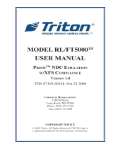
All displays have 2 connectors for a 2-wire or 3-wire RS485 communication interface and can be connected
into a communication network. If the displays are connected into a communication network (Fig. 1), any of
them can be controlled via a handheld infrared controler. Up to 127 devices can be connected to an NDC-net.
Fig. 1Connection of NDC displays in a communication network

4
Digital clocks – NDC Series / User Manual v. 2.11
2
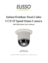
The easiest way of controlling the NDCclock is shown in fig. 2.
Fig. 2The easiest way of controlling the NDC clock.
2PROPERTIES
2.1 Display functions
•Time (display format)
−HH:MM (Hours:Minutes) NDC xxx/4;
−HH:MM:SS (Hours:Minutes:Seconds) NDC xxx/6.
•Date (display format)
−DD:MM (Day:Month) NDC xxx/4;
−DD:MM:YY (Day:Month:Year) NDC xxx/6.
•Temperature* (display format)
−-99° ÷ -10° ÷ -9.9° ÷ 99.9° NDC xxx/4;
−-99°C ÷ -10°C ÷ -9.9°C ÷ 99.9°C NDC xxx/6;
−A local thermal sensor (i.e. connected directy to the clock) can be located near the NDC or as part of
the frame (for extra fee). The precision of the displayed temperature is given by the precision of the
sensor.
* if a local thermal sensor is connected
•Stop watch
−SS.ss –> MM:SS NDC xxx/4
Seconds.hundredths of seconds with automatic switching to Minutes:Seconds when the seconds are
full;
−MM:SS.hh -> HH:MM:SS NDC .../6m
Minutes:Seconds.hundredths of seconds with selectable automatic switching to Hours:Minutes:Seconds
or a 99-minute mode (MM:SS.hh)
−Functions: START, STOP/FREEZE (intermediate time, the measured time runs in the background),
RESUME, RESET ;
−Automatic restart of the stop watch when the maximum displayable time is reached;
−Remote control of the stop watch, external contact (with or without galvanic separation) or with a remote
button in the NDC-net.
•Counter (counting up/down)
−Automatic switching of the display format, range: 1 s to 99 days, 23 hours, 59 minutes, 59 seconds;
−COUNT-UP or COUNT-DOWN mode –adjustable limit;
−Functions: START, STOP/PAUSE, RESUME, RESET;
−Single or repeated run of the counter when the setup limit is reached;
−Switchable counter time correction due to a time change (new time setting) or external time
synchronisation;
−Control of the counter via a remote control, an external contact (with or without galvanic separation) or
aremote button in the NDC-net;
−Possibility to switch on either the internal or a remote relay (close contact) when the limit is reached.
•Switch clock (time interval programming)
−Programmable 16 intervals of switching on the output relay in a single day;
−Setting of the relay switch on period from 0.01 –99 sec;
−Weekly calendar, setting of switch-on days (from Sunday to Saturday).
•Data from remote sensors (in NDC-net)
−Possibility to display data from 2 remote sensors connected to the NDC-net (e.g. external temperature
sensor, humidity sensor, pressure sensor, ...). It is possible to set on the clock the remote sensors whose
data will be displayed. If a local thermal sensor is connected, then it is possible to display just one figure
from a remote sensor.
•The clock allows alternate display of the above data, while the user has the possibility to program the
duration of their displaying in the range 0 ÷ 60s (0 –no data displayed).
•Automatic (depending on ambient light conditions) or manual brightness setting in 15 levels.

Digital clocks – NDC Series / User Manual v. 2.11
5
2
The easiest way of controlling the NDCclock is shown in fig. 2.
Fig. 2The easiest way of controlling the NDC clock.
2PROPERTIES
2.1 Display functions
•Time (display format)
−HH:MM (Hours:Minutes) NDC xxx/4;
−HH:MM:SS (Hours:Minutes:Seconds) NDC xxx/6.
•Date (display format)
−DD:MM (Day:Month) NDC xxx/4;
−DD:MM:YY (Day:Month:Year) NDC xxx/6.
•Temperature* (display format)
−-99° ÷ -10° ÷ -9.9° ÷ 99.9° NDC xxx/4;
−-99°C ÷ -10°C ÷ -9.9°C ÷ 99.9°C NDC xxx/6;
−A local thermal sensor (i.e. connected directy to the clock) can be located near the NDC or as part of
the frame (for extra fee). The precision of the displayed temperature is given by the precision of the
sensor.
* if a local thermal sensor is connected
•Stop watch
−SS.ss –> MM:SS NDC xxx/4
Seconds.hundredths of seconds with automatic switching to Minutes:Seconds when the seconds are
full;
−MM:SS.hh -> HH:MM:SS NDC .../6m
Minutes:Seconds.hundredths of seconds with selectable automatic switching to Hours:Minutes:Seconds
or a 99-minute mode (MM:SS.hh)
−Functions: START, STOP/FREEZE (intermediate time, the measured time runs in the background),
RESUME, RESET ;
−Automatic restart of the stop watch when the maximum displayable time is reached;
−Remote control of the stop watch, external contact (with or without galvanic separation) or with a remote
button in the NDC-net.
•Counter (counting up/down)
−Automatic switching of the display format, range: 1 s to 99 days, 23 hours, 59 minutes, 59 seconds;
−COUNT-UP or COUNT-DOWN mode –adjustable limit;
−Functions: START, STOP/PAUSE, RESUME, RESET;
−Single or repeated run of the counter when the setup limit is reached;
−Switchable counter time correction due to a time change (new time setting) or external time
synchronisation;
−Control of the counter via a remote control, an external contact (with or without galvanic separation) or
aremote button in the NDC-net;
−Possibility to switch on either the internal or a remote relay (close contact) when the limit is reached.
•Switch clock (time interval programming)
−Programmable 16 intervals of switching on the output relay in a single day;
−Setting of the relay switch on period from 0.01 –99 sec;
−Weekly calendar, setting of switch-on days (from Sunday to Saturday).
•Data from remote sensors (in NDC-net)
−Possibility to display data from 2 remote sensors connected to the NDC-net (e.g. external temperature
sensor, humidity sensor, pressure sensor, ...). It is possible to set on the clock the remote sensors whose
data will be displayed. If a local thermal sensor is connected, then it is possible to display just one figure
from a remote sensor.
•The clock allows alternate display of the above data, while the user has the possibility to program the
duration of their displaying in the range 0 ÷ 60s (0 –no data displayed).
•Automatic (depending on ambient light conditions) or manual brightness setting in 15 levels.
3
2.2 Display
The height of the display elements is 57, 100, 160 or 212 mm (readability up to 23, 40, 70 and 100 m
respectively). NDC 57/x and NDC 100/x types use superbright 7-segment LED modules. Other LED colours
are possible by agreement for an extra fee. NDC 160/x and NDC 212/x types use superbright elliptic LEDs to
ensure their legibility even in direct sunlight (outdoor).
2.3 Synchronisation, precision
•Possibility of external time synchronisation by means of synchronisation modules (e.g. GPS receiver).
•Time display precision:
–Autonomous time: ±30sec/month (in +20°C ÷ +30°C temperature range);
–When an external synchronisation module is connected, the precision is given by the precision of the
synchronisation.
2.4 Inputs, outputs
•RS485 interface with galvanic isolation for the interconnection with other devices in an NDC-net.
•An input for the connection of a local button with or without galvanic separation for controlling the stop
watch/counter. The maximum length of the local button’s cable is 3 –5 m (according to the level of
interference).
•An input for the connection of a local thermal sensor (2 m as standard,or up to 5 m max. as per request)
•Built-in output relay 2 A/250 VAC, which can be closed for 0.1 s – 99 s in the counter mode when the setup
limit is reached or as the output of the switch clock.
•GPS Time Receiver input.
2.5 Settings
•Time setting manual, wireless via an IR controller or automatic, when an external synchronisation module
is connected.
•Manual or automatic LED brightness control based on the external illumination.
•Programming and setting of the clock via a wireless IR controller (max. perpendicular distance 15 m):
−Time and date setting;
−Activation of selected display modes (time, date, temperature, stop watch, counter, remote sensor) –
intervals of alternating data display;
−Limit and modes for the counter;
−Stop watch format;
−Stop watch and counter control;
−Enabling/disabling of daylight saving time (DST);
−Time shifting in the range ±23 hrs 59 min –correct displaying of times in different time zones with external
synchronisation;
−Manual time setting;
−Counter relay switch-on time setting;
−Selection of a local or remote sensor 1 in an NDC-net to be displayed;
−Selection of a local or remote sensor 2 in an NDC-net to be displayed;
−Selection of the remote input in an NDC-net (only the Master clock, see chapter 2.9 NDC-net
communication network below);
−Interval of synchronisation with other clocks in the NDC-net (only the Master clock);
−Switching clock –times and periods of switching-on the internal relay, weekly calendar.
2.6 Modifications and dimensions
•NDC 57/x, 100/x – frame of the clock is made of high-quality anodised aluminium profiles in a matt platinum
grey colour with a metallic appearance. Protection class: IP 20. Operation temperature range: -5°C ÷
+50°C.
•NDC 160/x, 212/x–outdoor clock, installed in an internal steel, powder paint coated frame; the external
cover frame is made of aluminium profiles in the colour of matt natural anodised aluminium. Protection
Class: IP 54. Operation temperature range: -30°C ÷ +50°C.
Display
Width
Height
Thickness
Readability range
Poznámky
NDC 57/4
360
150
38
23 m
wall-mounted
NDC 57/6
460
150
38
23 m
wall-mounted
NDC 100/4
530
200
38
40 m
wall-mounted
NDC 100/6
730
200
38
40 m
wall-mounted
NDC 160/4
685
340
110/217*
70 m
* with tilting wall bracket
NDC 160/6
990
340
110/217*
70 m
* with tilting wall bracket
NDC 212/4
890
400
110/217*
100 m
* with tilting wall bracket
NDC 212/6
1280
400
110/217*
100 m
* with tilting wall bracket

6
Digital clocks – NDC Series / User Manual v. 2.11
4
2.7 Power supply
Standard 230 VAC/50 Hz,12 VDC and 24 VDC for extra fee.
2.8 System time network
•Possibility to create unified time systems in an NDC-net without the necessity to use special master clock.
The unified time network may contain NDC clocks, GPS receiver, a synchronisation time module (Network
Time Server RS485), remote sensors (e.g. of temperature), remote buttons to control stop watch and the
counter and a remote output module (relay), controlled by the so called Master clock (i.e. standard NDC
clock setup as the Master, see below).
•Adjustable network clock synchronisation interval in the range 0 –255 min (only the Master clock).
2.9 NDC-net communication network
At the physical level, the communication network is made by an RS485 interface with the baud rate 9600.
Devices with addresses 1 – 127 may be connected to the NDC-net bus, while there must be one NDC type
device with a dedicated address 1 in the function of the Master in the system. The bus negotiation and
communication control is always controlled by the Master device.
Devices connected to the bus may be of the following types:
•NDC clock –It displays data and, together with a remote controller, provides a user interface for the setting
and controlling of the system. The network must contain one NDC clock with the address set to 1 (Master
clock), which provides the control of the NDC-net.
•Synchronisation device –its role is to provide precise time to the rest of the devices. The source of that
time may be a GPS signal, DCF-77, a PC, an embedded module with an RS485 line and a protocol
converter to the NDC-net.
•Sensors –Within the range of the NDC-net they measure general quantities (usually temperature, but also
humidity, pressure,...) and, after their processing, they send the data along the network to NDC devices
for displaying. Data from one of two sensors may be allocated to each NDC clock. The sensor modules
will complement the offer depending on the demand on the market and the development possibilities.
•Remote buttons –They allow to place buttons for controlling the stop watch and the counter into a longer
distance from the controlled NDC within the NDC-net.
•Remote access –allows to place the switching relay or an open-collector type output to a longer distance
from the controlling NDC within the NDC-net. This output may be controlled only by the Master clock.
3DISPLAY ACCESSORIES
Depending on the selected version of the connection of displays, the supply is complemented with the
necessary accessories.
3.1 Standard accessories
Type of display
Standard accessories
NDC 57/4
Power supply cable
flexible 1.5 m.
NDC 57/6
NDC 100/4
NDC 100/6
NDC 160/4
Connector for the
power supply cable.
(Cable is not supplied.)
NDC 160/6
NDC 212/4
NDC 212/6
3.2 Optional accessories
•Handheld IR Remote Control –for setting clock parameters.
(Parameters such as time, date, on/off time period of each displayed value, brightness, etc.).
•Temperature sensor –for displaying local or remote temperature (as per type ordered).
•GPS Time Receiver –for automatic time/date synchronization with GPS
(GPS Timer Receiver cable length can be 5 m or 10 m max.,depending on type ordered).
Several modules can be connected to NDC series clocks and to the NDC-net through a communication bus
based on RS485, which communicate with the NDC-protocol. The range of such modules is widened
continually.

Digital clocks – NDC Series / User Manual v. 2.11
7
4
2.7 Power supply
Standard 230 VAC/50 Hz,12 VDC and 24 VDC for extra fee.
2.8 System time network
•Possibility to create unified time systems in an NDC-net without the necessity to use special master clock.
The unified time network may contain NDC clocks, GPS receiver, a synchronisation time module (Network
Time Server RS485), remote sensors (e.g. of temperature), remote buttons to control stop watch and the
counter and a remote output module (relay), controlled by the so called Master clock (i.e. standard NDC
clock setup as the Master, see below).
•Adjustable network clock synchronisation interval in the range 0 –255 min (only the Master clock).
2.9 NDC-net communication network
At the physical level, the communication network is made by an RS485 interface with the baud rate 9600.
Devices with addresses 1 – 127 may be connected to the NDC-net bus, while there must be one NDC type
device with a dedicated address 1 in the function of the Master in the system. The bus negotiation and
communication control is always controlled by the Master device.
Devices connected to the bus may be of the following types:
•NDC clock –It displays data and, together with a remote controller, provides a user interface for the setting
and controlling of the system. The network must contain one NDC clock with the address set to 1 (Master
clock), which provides the control of the NDC-net.
•Synchronisation device –its role is to provide precise time to the rest of the devices. The source of that
time may be a GPS signal, DCF-77, a PC, an embedded module with an RS485 line and a protocol
converter to the NDC-net.
•Sensors –Within the range of the NDC-net they measure general quantities (usually temperature, but also
humidity, pressure,...) and, after their processing, they send the data along the network to NDC devices
for displaying. Data from one of two sensors may be allocated to each NDC clock. The sensor modules
will complement the offer depending on the demand on the market and the development possibilities.
•Remote buttons –They allow to place buttons for controlling the stop watch and the counter into a longer
distance from the controlled NDC within the NDC-net.
•Remote access –allows to place the switching relay or an open-collector type output to a longer distance
from the controlling NDC within the NDC-net. This output may be controlled only by the Master clock.
3DISPLAY ACCESSORIES
Depending on the selected version of the connection of displays, the supply is complemented with the
necessary accessories.
3.1 Standard accessories
Type of display
Standard accessories
NDC 57/4
Power supply cable
flexible 1.5 m.
NDC 57/6
NDC 100/4
NDC 100/6
NDC 160/4
Connector for the
power supply cable.
(Cable is not supplied.)
NDC 160/6
NDC 212/4
NDC 212/6
3.2 Optional accessories
•Handheld IR Remote Control –for setting clock parameters.
(Parameters such as time, date, on/off time period of each displayed value, brightness, etc.).
•Temperature sensor –for displaying local or remote temperature (as per type ordered).
•GPS Time Receiver –for automatic time/date synchronization with GPS
(GPS Timer Receiver cable length can be 5 m or 10 m max.,depending on type ordered).
Several modules can be connected to NDC series clocks and to the NDC-net through a communication bus
based on RS485, which communicate with the NDC-protocol. The range of such modules is widened
continually.
5
4INSTALLATION OF A DISPLAY
4.1 Display mount
The display is mounted to the wall by means of brackets on the rear side using supplied screws or similar ones
with pan or button head. Head of the screw should protrude from the wall so that the display can be hanged
easily. If there are self adhesive rubber bumpers included with the package, place them to the lower corners
of the rear panel, like on the picture.
Note: Rubber bumpers can be already placed from the factory.
4.2 NDC 57/x, NDC 100/x displays, 230 VAC power supply
Connect a two-wire power supply cable to the power supply terminal on the display’s power supply board. The
terminals are accessible after the removal of the tiltable part of the rear wall. The cable goes through the
bushing in the tiltable part, marked as “230 V”. The standard length of the cable is about 2 m. The device
includes a melting fuse, located on the power supply board. The details of the power supply terminals can be
found in the circuit diagram.
4.3 NDC 160/x, NDC 212/x displays, 230 VAC power supply
The mains power supply connector at the back of the display is marked as “AC 230V”. The connection of the
mains power supply 230 VAC is done through a 4-pole mains power supply connector with an outlet for the
connection of the PE wire. The type of connector and the connection of its pins can be found in the connection
diagram. A melting fuse is used in the device and it is located on the power supply board.
4.4 Connection of displays in the NDC-net
Communication connectors are used for the connection of the displays into the communication network. The
connectors are located at the back of the display and they are marked as “RS485” and “17 V / RS485”. The
type of the connector used and its connection are described in detail in the clock’s circuit diagram. If some
voltage is outlet on a connector’s contacts (e.g. +17 VDC, GND), that voltage is then used for powering
modules from the optional accessories (temperature sensor, GPS receiver, ...).
The displays are interconnected in parallel by a two-wire or, if necessary, 3-wire communication cable,
according to the recommendations for the RS485 interface. The manufacturer recommends to use the FTP
24AWG 4x2x0.53 CAT5 cable, which is largely used in the creation of structured cabling of computer networks.
Only one or two pairs of wires of the cable are used.
4.5 Connection of GPS Time Receiver
The clock is equipped with input ”GPS RECEIVER, 5V / RS232“, for connecting a GPS Time Receiver. GPS
Time receiver is available as optional accessory in two versions:
1. GPS Time Receiver,cable length 5 m, chipset u-Blox 6, sensitivity -162 dBm.
2. GPS Time Receiver,cable length 10 m, chipset u-Blox 8, sensitivity -167 dBm (higher sensitivity).
4.6 Connection of communication modules and optional accessories
Communication connector (15V / RS485) allows to connect various communication modules offered as
optional accessories (Network Time Server RS485, remote thermal sensor, etc.).
The modules can be powered by the voltage from the clock, taken out to the communication connectors. In
such a case the module is galvanically connected to the clock and to the NDC-net. Such a solution is
usually suitable when no clock network is created (i.e. 1 clock is interconnected with just 1 module); when the
distance between the clock and the module is short (up to about 5 m) or in an environment without industrial
interference (however at maximum distance of about 20 m).

8
Digital clocks – NDC Series / User Manual v. 2.11
6
In the case of required galvanic separation of devices, it is necessary to use the respective modules in the
modification with galvanic separation and to provide the powering of the modules from separate power
supplies. In such a case galvanic separation of individual devices in the NDC-net between each-other and
from the mains is guaranteed. This solution is necessary when the device network is larger, and is installed
along power cables, metal piping or near other sources of interference, in an outdoor environment, between
buildings, etc. The power supply is connected to the module through a data distribution box, while its distance
from the module should not exceed 20 m.
5SETTING, CONTROLLING AND PROGRAMMING OF THE NDC CLOCKS
5.1 Table of the menu, default settings
MENU Submenu
Display
(alteration
parameter/value)
Default
setting
(after reset)
diSP
DISPLAY
Time reading period
Date reading period
Coundown reading period
Sensor 1 reading period
Sensor 2 reading period
Stopwatch reading period
tMPE
dtPE
CdPE
S1PE
S2PE
StPE
15 s
5 s
0 s
0 s
0 s
0 s
tIME
TIME
Year setting
Month setting
Day setting
Hour setting
Minute setting
Shift of hours setting
Shift of minutes setting
Automatic switching of Daylight saving time on/off
yEAr
Mon
dAy
Hour
Min
Sh_H
Sh_M
dSt
current
current
current
current
current
0
0
On
Cnt
COUNTER
Count direction setting
Limit –days setting
Limit –hours setting
Limit –minutes setting
Limit –seconds setting
Relay period setting
Counter repeat setting
Counter correction enable/disable
Cdir
LM_d
LM_H
LM_M
LM_S
rLPE
CrPt
Ccor
uP
0
0
0
0
0
OFF
On
Set
SET
Brightness setting
Display address setting
Configuration, see submenu
Sensor 1 address setting
Sensor 2 address setting
Push-button address setting
Remote output address setting
Synchronization period setting
Stopwatch mode setting –for NDC xxx/4
–for NDC xxx/6
BriG
diAd
ConF
S1Ad
S2Ad
PbAd
roAd
SyPE
StMo
15 (max)
001 (Master)
–
000
000
000
000
1
M99
M59
PrG
PROGRAM
Switch on time
Relay period
Week days
S_tM
rEL
WdA
all 00:00
all 0
all OFF
ConF submenu, network configuration (Configuration)
ConF
Configuration run run
Device list LiSt
Reset to default settings rSt

Digital clocks – NDC Series / User Manual v. 2.11
9
6
In the case of required galvanic separation of devices, it is necessary to use the respective modules in the
modification with galvanic separation and to provide the powering of the modules from separate power
supplies. In such a case galvanic separation of individual devices in the NDC-net between each-other and
from the mains is guaranteed. This solution is necessary when the device network is larger, and is installed
along power cables, metal piping or near other sources of interference, in an outdoor environment, between
buildings, etc. The power supply is connected to the module through a data distribution box, while its distance
from the module should not exceed 20 m.
5SETTING, CONTROLLING AND PROGRAMMING OF THE NDC CLOCKS
5.1 Table of the menu, default settings
MENU Submenu
Display
(alteration
parameter/value)
Default
setting
(after reset)
diSP
DISPLAY
Time reading period
Date reading period
Coundown reading period
Sensor 1 reading period
Sensor 2 reading period
Stopwatch reading period
tMPE
dtPE
CdPE
S1PE
S2PE
StPE
15 s
5 s
0 s
0 s
0 s
0 s
tIME
TIME
Year setting
Month setting
Day setting
Hour setting
Minute setting
Shift of hours setting
Shift of minutes setting
Automatic switching of Daylight saving time on/off
yEAr
Mon
dAy
Hour
Min
Sh_H
Sh_M
dSt
current
current
current
current
current
0
0
On
Cnt
COUNTER
Count direction setting
Limit –days setting
Limit –hours setting
Limit –minutes setting
Limit –seconds setting
Relay period setting
Counter repeat setting
Counter correction enable/disable
Cdir
LM_d
LM_H
LM_M
LM_S
rLPE
CrPt
Ccor
uP
0
0
0
0
0
OFF
On
Set
SET
Brightness setting
Display address setting
Configuration, see submenu
Sensor 1 address setting
Sensor 2 address setting
Push-button address setting
Remote output address setting
Synchronization period setting
Stopwatch mode setting –for NDC xxx/4
–for NDC xxx/6
BriG
diAd
ConF
S1Ad
S2Ad
PbAd
roAd
SyPE
StMo
15 (max)
001 (Master)
–
000
000
000
000
1
M99
M59
PrG
PROGRAM
Switch on time
Relay period
Week days
S_tM
rEL
WdA
all 00:00
all 0
all OFF
ConF submenu, network configuration (Configuration)
ConF
Configuration run run
Device list LiSt
Reset to default settings rSt
7
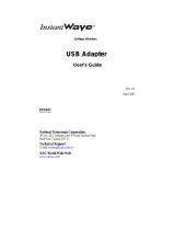
5.2 Layout of IR controller’s buttons
5.3 Work with the menu, control through the IR controller
In the display mode, the clock does not accept any control codes from the IR controller except the code of the
SELECT button. That prevents inadvertent simultaneous setting of several clocks, if they are too close to each
other (within the range of the IR). When you push the SELECT button, the display will show its address in the
{Axxx} format, where xxx is a number from the range 0 to 126. The required clock is selected by entering its
three-digit address 0– 9 buttons without the need to confirm. When a correct address is entered, {Menu} will
be displayed on the respective clock, which means that the clock is in the setting mode. If an incorrect address
is set or the address is not entered within 3 seconds, the display will move automatically into the standard
displaying mode. {Menu} will be displayed only upon entering the menu to confirm the correctness of the
previous steps, but is it not displayed when browsing in the menu.
Arrow buttons ▲ and ▼ are used for browsing in the menu. A selected submenu should be confirmed by the
OK button. When the browsing stops in a submenu, after 2 seconds the value of the displayed parameter and
its name will be displayed alternately (value for 0.5 sec / name for 1.5 sec). It is possible to continue with
browsing also in this mode, until the required parameter is found.
To change the value of a parameter confirm that parameter with the OK button – its value will be displayed
permanently and it is possible to modify it with numerical buttons. A digit that is being modified will blink. If the
value of the parameter is a non-numerical one (ON/OFF, decimal point, minus sign), use the ◄/► buttons to
switch to the required value. Confirm the new value by pressing the OK button. If the new value is not confirmed
within 7 seconds, a move one level up will occur (i.e. to the list of parameters) and the original value will remain
unchanged.
Button
Colour
Description of function
ESC
ESC to one level up
SELECT
Select device
0–9
Enter digits
◄/►
Switch between values, DP
position, +/-
▲
Move up in the menu
▼
Move down in the menu
OK
Confirmation button
►
Start
▐ ▌
Pause
■
Stop
RESET
Reset
▲up button
►
right button
◄
left button
▼
down button

10
Digital clocks – NDC Series / User Manual v. 2.11
8
If the value being confirmed is outside the allowed range, an error message {Err} will be displayed for 3 sec
after the confirmation. In this case no modification of the value being set will occur (the original one will be
retained).
In any setting phase it is possible to cancel the setting by pressing the ESC button without modifying the
parameter being set. This button is used for the return one level up in the menu, up to the complete ending of
the menu. If no activity is registered in the setting mode (i.e. the menu) for 60 sec, the display will return
automatically into the display mode.
5.4 Data display period setting {diSP}
({MEnu}→){diSP}→{tMPE}
({MEnu}→){diSP}→{dtPE}
({MEnu}→){diSP}→{CdPE}
({MEnu}→){diSP}→{S1PE}
({MEnu}→){diSP}→{S2PE}
({MEnu}→){diSP}→{StPE}
In this menu you can define the periods for which individual data of the clock will be displayed alternately. The
respective data is displayed for the set period (e.g. time, {tMPE}) and in the order in which the items are
arranged in the menu. If any parameter is set to 0, the respective item will not be displayed.
To start the setting, in the main menu activate the {diSP} item and confirm it with the OK button (see Chapter
5. SETTING, CONTROLLING AND PROGRAMMING OF THE NDC CLOCKS).
The periods of displaying individual data items is specified in seconds, while it is possible to set that parameter
for the following items:
{tMPE} Time Period default 15;
{dtPE} Date Period default 5;
{CdPE} Coundown Period default 0;
{S1PE} Sensor 1 Period default 0;
{S2PE} Sensor 1 Period default 0;
{StPE} Stopwatch period default 0.
The range of allowed values of these items is between 0 and 60. If no local or remote (thermal) sensor is
connected, it is necessary to leave both {S1PE} and {S2PE} = 0.
5.5 Time setting {tIME}
To set the clock, first it is necessary to activate the {tIME} item in the main menu and confirm it with the OK
button.
5.5.1 Time setting {Hour}, {Min}
({MEnu}→){tIME}→{Hour}
({MEnu}→){tIME}→{Min}
The time setting consists of the setting of two values:
{Hour} setting of hours in the range 0 – 23;
{Min} setting minutes in the range 0 – 59.
In the case of correct setting and confirming of minutes, the seconds will be reset at the moment of
confirmation.
Note:
1. Before the time setting itself, it is necessary to check and set correctly the time zone (shift against the
UTC) for which the set time is to be valid (items {Sh_H} and {Sh_M}). This is important for the correct move
to the winter/summer time; otherwise the move will occur on an incorrect hour (if automatic switching to
the winter/summer time (DST) is enabled, see chapter 5.5.4 Switching between the summer/winter time
(Daylight Saving Time) {dSt}). For the Central European Time (CET) the shift is +1 hour, for the UTC/GMT
time the shift is 0. When the time zone is set, the clock will display the local time.
2. If the local time is set first and the time zone second, the clock will display the shifted time.
5.5.2 Date setting {YEAr}, {Mon}, {dAY}
({MEnu}→){tIME}→{YEAr}
({MEnu}→){tIME}→{Mon}
({MEnu}→){tIME}→{dAY}

Digital clocks – NDC Series / User Manual v. 2.11
11
8
If the value being confirmed is outside the allowed range, an error message {Err} will be displayed for 3 sec
after the confirmation. In this case no modification of the value being set will occur (the original one will be
retained).
In any setting phase it is possible to cancel the setting by pressing the ESC button without modifying the
parameter being set. This button is used for the return one level up in the menu, up to the complete ending of
the menu. If no activity is registered in the setting mode (i.e. the menu) for 60 sec, the display will return
automatically into the display mode.
5.4 Data display period setting {diSP}
({MEnu}→){diSP}→{tMPE}
({MEnu}→){diSP}→{dtPE}
({MEnu}→){diSP}→{CdPE}
({MEnu}→){diSP}→{S1PE}
({MEnu}→){diSP}→{S2PE}
({MEnu}→){diSP}→{StPE}
In this menu you can define the periods for which individual data of the clock will be displayed alternately. The
respective data is displayed for the set period (e.g. time, {tMPE}) and in the order in which the items are
arranged in the menu. If any parameter is set to 0, the respective item will not be displayed.
To start the setting, in the main menu activate the {diSP} item and confirm it with the OK button (see Chapter
5. SETTING, CONTROLLING AND PROGRAMMING OF THE NDC CLOCKS).
The periods of displaying individual data items is specified in seconds, while it is possible to set that parameter
for the following items:
{tMPE} Time Period default 15;
{dtPE} Date Period default 5;
{CdPE} Coundown Period default 0;
{S1PE} Sensor 1 Period default 0;
{S2PE} Sensor 1 Period default 0;
{StPE} Stopwatch period default 0.
The range of allowed values of these items is between 0 and 60. If no local or remote (thermal) sensor is
connected, it is necessary to leave both {S1PE} and {S2PE} = 0.
5.5 Time setting {tIME}
To set the clock, first it is necessary to activate the {tIME} item in the main menu and confirm it with the OK
button.
5.5.1 Time setting {Hour}, {Min}
({MEnu}→){tIME}→{Hour}
({MEnu}→){tIME}→{Min}
The time setting consists of the setting of two values:
{Hour} setting of hours in the range 0 – 23;
{Min} setting minutes in the range 0 – 59.
In the case of correct setting and confirming of minutes, the seconds will be reset at the moment of
confirmation.
Note:
1. Before the time setting itself, it is necessary to check and set correctly the time zone (shift against the
UTC) for which the set time is to be valid (items {Sh_H} and {Sh_M}). This is important for the correct move
to the winter/summer time; otherwise the move will occur on an incorrect hour (if automatic switching to
the winter/summer time (DST) is enabled, see chapter 5.5.4 Switching between the summer/winter time
(Daylight Saving Time) {dSt}). For the Central European Time (CET) the shift is +1 hour, for the UTC/GMT
time the shift is 0. When the time zone is set, the clock will display the local time.
2. If the local time is set first and the time zone second, the clock will display the shifted time.
5.5.2 Date setting {YEAr}, {Mon}, {dAY}
({MEnu}→){tIME}→{YEAr}
({MEnu}→){tIME}→{Mon}
({MEnu}→){tIME}→{dAY}
9
The date setting consists of setting the values of:
{YEAr} setting of the year in the range 0 – 99 for the years 2000 –2099;
{Mon} month setting in the range 1 – 12;
{dAY} day setting in the range 1 – 31 (or 28, 29, 30, 31, depending on the specific month and year).
5.5.3 Time zones, time shift setting {Sh_H}, {Sh_M}
({MEnu}→){tIME}→{Sh_H}
({MEnu}→){tIME}→{Sh_M}
In order to be able to switch correctly to the summer/winter time and display correctly the time in other time
zones (e.g. in Tokyo, New York, etc.), which are shifted against the reference time (UTC), the clock allows to
set a time correction (shift) against the synchronisation or internal time by up to ±23 hours and 59 minutes.
Setting of the correction:
{Sh_H} setting of the correction of the time zone, hours in the range ±0 – 23 default 0;
{Sh_M} setting of the correction of the time zone, minutes in the range 0 – 59 default 0.
When setting the hours of the time zone correction {Sh_H}, it is also necessary to specify whether the
correction will be added to the internal time or whether it will be subtracted from it. With the ◄/►buttons set
the minus (-) sign before the numerical value to subtract the correction or no sign (+) to add the correction.
5.5.4 Switching between the summer/winter time (Daylight Saving Time) {dSt}
({MEnu}→){tIME}→{dSt}
The clock allows to set whether the switchover to the summer/winter time should occur or not.
{dSt} Automatic switching {On}/{OFF} defalult {On}.
If this function is on, the clock will be set to the summer time on the last March Sunday (from 1:00 to 2:00
UTC). When the correct time zone is set, this transition will take place in the correct local time.
This function is just a program one, while it is based on the current time and date, which have to be set correctly
(or time synchronisation has to be ensured).
Note: If the clock (clock network) is connected to a synchronisation device (GPS receiver, etc.) which itself
provides the correction of the summer/winter time, this function has to be switched off on all clocks
otherwise the clocks will show incorrect time during the summer time (1 hr ahead).
5.6 General settings {SEt}
For the general setting of the clock first it is necessary to activate {SEt} item in the main menu and confirm it
with the OK button.
5.6.1 Brightness setting {BriG}
({MEnu}→){SEt}→{BriG}
The value of the display brightness may be set in 15 levels or an automatic brightness setting, which controls
the display’s brighness depending on the ambient light, may be set.
When you activate and select the {BriG} item, its current value, 1 – 15 or {Auto} will be displayed. With the up
▲and down ▼ buttons set the required brightness level. The display will change its brightness accordingly. If
{Auto} is set, the display’s brightness will be controlled automatically according to the ambient light.
Note: In contrast with other settings, the set value remains stored in the memory without confirmation. To
return to the menu, press the OK or ESC button, othwewise the return will occur after 7 sec of inactivity.
5.6.2 Display address setting {diAd}
({MEnu}→){SEt}→{diAd}
The address of a device is used for unique identification of a device in the network of a number of NDC clocks.
In general, each device in the NDC-net (NDC, sensor, synchronisation module,...) has to have a unique
address.
Address setting:
{diAd} Address setting in the range 1 – 126 default 1.
After the selection and confirmation of the {diAd} parameter the current value of the address will be displayed.
The range of the allowed values of the address is 1 – 126. Address 0 is reserved as the global one for
addressing all connected devices, address 127 is reserved for the device that provides the time
synchronisation, e.g. a GPS synchronisation module.
In each NDC-net in which synchronisation is required, one NDC clock has to be set as the Master. The Master

12
Digital clocks – NDC Series / User Manual v. 2.11
10
has a dedicated address 1, i.e. the Master is specified by setting that address. Master also secures the control
of the whole NDC-net. In the case of non-existence or availability of a synchronisation device, it also takes
over the time synchronisation.
Note: Even if just one NDC clock is interconnected with a synchronisation device (e.g. GPS), it has to be set
as the Master (i.e. address 1).
5.6.3 Network configuration {ConF}
({MEnu}→){SEt}→{ConF}
See a detailed description in a separate chapter 6. INSTALLATION AND CONFIGURATION OF THE NDC-
net.
5.6.4 Allocation of sensors, temperature display, address setting {S1Ad}, {S2Ad}
({MEnu}→){SEt}→{S1Ad}
({MEnu}→){SEt}→{S2Ad}
An NDC-net may contain any number of sensors and NDC clocks (up to the maximum number of enabled
addreses). An NDC clock may display data from at maximum two sensors. By entering addresses {S1Ad} and
{S2Ad} you will specify from which sensor the data will be displayed. The data from a single sensor may be
displayed on a number of NDC clocks, notably on those that have its address in the items {S1Ad} or {S2Ad}.
If a local thermal sensor is connected and there is a requirement to display that temperature on the respective
clock, it is necessary to set the {S1Ad} or {S2Ad} address equal to the given clock (= {diAd}). So, for example,
if you want to display the local temperature on the clock with address “A005”, set the sensor’s address, {S1Ad}
or {S2Ad} on that clock to “A005”. If no sensor is connected, the display will display dashes (------) on all
positions.
If you want to display a data from a remote sensor (if it is connected), it is necessary to set the adresss fo that
remote sensor. You can find the address in the list of devices in the network (see chapter 6.3 Viewing of the
list of devices {LiSt}). So, if, for example, you want to display the temperature of a remote sensor whose
address is “A043” on the display, set the address of the sensor, {S1Ad} or {S2Ad}, on that clock to “A043”. If
the remote sensor with address “A043” is connected correctly, the clock will show its data, otherwise the text
{noSEnS}, (NDC xxx/6) or {noSE} (NDC xxx/4) will be shown, which means that there is no sensor with that
address in the network or there may be problems with the communication with that module.
If there is a synchronisation module with an integrated thermal sensor in the NDC-net and there is a
requirement to display its temperature data on some clocks, it is necessary to set the address of that sensor,
{S1Ad} or {S2Ad}, to „A127” on those clocks, since the address of the synchronisation module is fixed (“A127“).
The addresses of the rest of the modlules are configurable by DIP switches on them.
Note: For the future, it is counted with the development of sensor modules that will provide display data (e.g.
module providing details of temperature and humidity, temperature and atmospheric pressure...). If it is
necessary to display both details, for both parameters, {S1Ad} and {S2Ad}, it is necessary to set the
same address of the remote sensor. Figure 1 will be displayed in the display interval {S1PE} and Figure
2in the display interval {S2PE}.
5.6.5 Allocation of the remote button, address setting {PbAd}
({MEnu}→){SEt}→{PbAd}
If it is necessary to control the stopwatch/counter from a remote location, it is possible to use the remote output
module. With that module it is then possible to control the stopwatch and counter functions within the range of
the NDC-net communication network.
With one remomote input module it is possible to control those stopwatches and counters running on different
NDC clocks that have its address set by item {PbAd}. In an NDC-net it is also possible to connect a number of
remote input modules and allocate them to individual clocks by means of the {PbAd} address.
5.6.6 Allocation of a remote input, address setting {roAd}
({MEnu}→){SEt}→{roAd}
In an NDC-net it is possible to connect a remote output module, which has one switching relay output and one
open collector output. These outputs can be controlled only by the Master clock (address “A001”). On the
master clock it is therefore necessary to set the address of the remote output {roAd} identical with the address
of the remote output module. The events at which outputs on a remote module are activated are identical with
the events at which the internal relay on the clock switches, i.e. when the counter limits are reached or when
the switching tooks place in the switching clock mode. The period of output module relay switch on state is
identical with the set switch on state of the internal relay set by {rLPE} or {rE0} –{rE15} in the {rEL} submenu.

Digital clocks – NDC Series / User Manual v. 2.11
13
11
5.6.7 Setting of the time synchronisation period {SyPE}
({MEnu}→){SEt}→{SyPE}
The time synchronisation period specifies how often an NDC clock or a network of NDC clocks will be
synchronised in an NDC-net. If there is no synchronisation module in the network, of if it does not sent
synchronisation data into the network, the synchronisation role is taken upon by the clock with address “A001”,
so-called Master clock. The period is specified in minutes.
{SyPE} period setting in the range 0 –255 defalult 1.
If 0 is set, the time synchronisation is switched off, i.e. the clock (or a clock network) is not synchronised.
5.6.8 Stopwatch mode setting {StMo} (only for 6-digit NDC clocks)
({MEnu}→){SEt}→{StMo}
6-character stopwatch (NDC xxx/6) can work in two modes:
a/ Hourly mode {M_59}
In this mode, when 59 minutes and 59.99 seconds are reached, the stopwatch will move to a new hour
and continues in HH:MM:SS mode (59:59.99 →1:00:00→...→99:59:59).
b/ Minute mode {M_99}
After reaching the state 59 minutes and 59.99 seconds, the stopwatch will continue with counting minutes
up to 99th minute remaining in MM:SS.hh mode (59:59.99 →60:00.00→...→99:59.99).
After reaching the maximum time, the stopwatch will start counting from the beginning.
Setting of the mode.
{StMo} setting of {M_59}/{M_99} (hour/minute mode), NDC xxx/4 default {M_99};
NDC xxx/6 default {M_59}.
After choosing the {StMo} parameter, the display will show the current mode of the stop watch. By the Switch
between values button ◄/► it is possible to switch between the hour and minute mode of the stopwatch.
Note: The 4-digit clock (NDC xxx/4) always works in the minute mode of the stopwatch, i.e. up to 99:59.
5.7 Stopwatch
The NDC clock may be used in the stopwatch mode. For displaying stopwatch data, it is necesssary to set the
{StPE} parameter to the required period of displaying, see chapter 5.4 Data display period setting {diSP}. If
you want to ensure only the displaying of the stopwatch, set the parameters for the rest of the displayed data
to 0.
Types NDC xxx/4 display the time measurement by distinguishing of seconds:hundredths of seconds, with
automatic switching to minutes:seconds when seconds are filled up, up to the maximum 99:59. NDC xxx/6
types allow to work in two modes, so-called hourly one (up to 99:59:59) and a minute one (up to 99:59.99).
See more detailed information in chapter 5.6.8 Stopwatch mode setting {StMo} (only for 6-digit NDC clocks).
If the stopwatch is not stopped, when it reaches the maximum displayed value according to the selected mode,
it is reset automatically and continues with the measurement from the beginning.
5.7.1 Control of the stopwatch
The stopwatch can be controlled only if the measured time is currently shown on the display (e.g. in the case
of alternating display together with other data). Therefore we recommend not to alternate the stopwatch display
with other data and to display it alone.
5.7.1.1 Stopwatch control by a remote controller
When the clock is switched on or when it is reset, the display will show 00:00.00 or 00.00 and it is ready for
further operation.
The stopwatch is started by the START ► button. If the PAUSE ▐ ▌ button is pressed during the running, the
display will “freeze” the current value of the measured time (intermediate time), which the measurement will
continue in the background. After the pressing of the START ►button again the display will show the measured
time again.
If, during the measurement you press the STOP ■ button, the display will show the current value of the
measured time and stop the measurement. When you press the STOP ■ button when an intermediate time is
displayed (i.e. after the previous pressing of the PAUSE ▐ ▌ button) the time measurement running in the
background will stop and the final time will be displayed.
If the stowatch is in the stop mode, it is possible to start it again with the START ►button from the measured
time it displays.

14
Digital clocks – NDC Series / User Manual v. 2.11
12
The resetting of the stopwatch is done by the RESET button, but in order to do that, the time measurement
must be stopped (stop condition after pressing the STOP ■button).
5.7.1.2 Control of the stopwatch by a local button (TRIGGER INPUT)
The local button must be connected to the TRIGGER INPUT, see the connection diagram. This method of
control only supports the START and PAUSE functions, which are implemented by a short pressing of the
button (< 2.5 seconds). To activate the RESET button, you need to keep the button depressed for more than
2.5 seconds.
Let us assume a reset state of the stopwatch (00:)00.00 (after switching on or reset). Short pressing of the
button will start a time measurement (intermediate time), while the measurement will keep running in the
background (PAUSE). After the next pressing of the button, the measured time will be displayed again
(START), and so on.
The resetting of the stopwatch is done by a long pressing of the button in the PAUSE state.
5.7.1.3 Control of the stopwatch by a remote button
The remote button must be connected to the NDC-net and its address must be allocated to the clock/stopwatch
that is to be controlled by it, see chapter 5.6.5 Allocation of the remote button, address setting {PbAd}.
The stopwatch is controlled in the same way by the local button.
5.8 Counting up/down (Counter) {Cnt}
The counter allows to work in one of two modes, specifically the UP mode or the DOWN mode. In the UP
mode, the counter counts the time from the value (00:)00:00 up until a preset value. In the DOWN mode the
counter counts the time from the set value downwards to (00:)00:00. When the end of the interval is reached,
the built-in relay is switched on, while the duration of the switch-on state can be adjusted. In the settings it is
also possible to choose whether after ending the counting up/down the whole cycle is started again and how
the time counting should behave when the internal time setting is changed from outside.
During counting up/down, time is shown in the following format:
a) NDC xxx/4
DD .HH the dot blinks each second;
HH :MM the colon blinks each second;
MM : SS the colon is on permanently, seconds change;
SS seconds change.
b) NDC xxx/6
DD . HH :MM the colon blinks each second;
HH : MM : SS the colon is permanently on, seconds change;
MM : SS seconds change;
SS seconds change.
A detailed description of the above properties is contained in the following chapters, so please read them
carefully.
5.8.1 Counting direction setting {Cdir}
({MEnu}→){Cnt}→{Cdir}
To count time up, please select the UP mode [the counting starts on (00:)00:00 and ends on a preset limit], to
count time down, choose the DOWN mode [the counting starts on a preset limit and ends on (00:)00:00].
Setting of the count direction (mode):
{Cdir} (counting direction) {uP}/{dn} default UP.
The {uP}/{dn} values are switched between by the ◄/► buttons and confirmed by the OK button.
5.8.2 Counting limit setting {LM_d}, {LM_H}, {LM_M}, {LM_S}
({MEnu}→){Cnt}→{LM_d}
({MEnu}→){Cnt}→{LM_H}
({MEnu}→){Cnt}→{LM_M}
({MEnu}→){Cnt}→{LM_S}
In this menu, the start or end value of the limit is set (according to the selected counting direction). The limit is
in the format: days:hours:minutes:seconds (DD:HH:MM:SS), while individual items are set separately.
For the setting, in the main menu it is necessary to activate the {Cnt} item and confirm it by the OK button (see
chapter 5. SETTING, CONTROLLING AND PROGRAMMING OF THE NDC CLOCKS).
Limit setting:

Digital clocks – NDC Series / User Manual v. 2.11
15
13
{LM_d} Limit –days default 0;
{LM_H} Limit –hours default 0;
{LM_M} Limit –minutes default 0;
{LM_S} Limit –seconds default 0.
Ranges of the allowed values of limit items:
{LM_d} days 0–99 as a standard;
{LM_H} hod. 0–23 as a standard (0 –99 when ignoring the {LM_d} value setting);
{LM_M} min. 0–59 as a standard (0 –99 when ignoring the {LM_d}, {LM_H} value setting);
{LM_S} sec. 0–59 as a standard (0 –99 when ignoring the {LM_d}, {LM_H}, {LM_M} value setting).
Note:
Upon entering a non-standard value for any item, all items with a larger time value will be ignored. This allows
to adjust counting to special requirements.
Example after setting DD :HH :MM :SS the accepted value will be DD :HH :MM :SS
23 :19 :59 :30 23 :19 :59 :30
15 :87 :24 :14 00 :87 :24 :14
05 :87 :94 :10 00 :00 :94 :10
5.8.3 Output relay control, switch on time setting {rLPE}
({MEnu}→){Cnt}→{rLPE}
In both modes of the counter it is possible to select the activation of the output relay upon reaching the end of
the set interval -limit. Each NDC clock on which a counter is running, may activate its local relay output.
Through this menu the relay on period upon reaching the counter limit is set {rLPE}
{rLPE} relay period 0 –99 sec (0.01 –0.99 sec; 0.1 –9.9 sec; 1 –99 sec) default 0.
The on period is set in seconds. The value is entered as a double-digit number, while the position of the decimal
point is set by the ◄/► buttons as necessary a nd confirmed by the OK button.
It is also possible to control a remote output by a counter event. A precondition for that is that the remote output
must be allocated to that clock (see chapter 5.6.6 Allocation of a remote input, address setting {roAd}) and the
clock must be set as a Master. Then the output will be switched on simultaneously with the internal relay.
Note:
1. If the set relay on period is 0 sec, the relay will not be switched on at the selected time!
2. Switching of the relay is signalized by the LED in the right lower corner (after second or minute reading),
that is turned on all the time while relay is switched on.
5.8.4 Counter repeat setting {CrPt}
({MEnu}→){Cnt}→{CrPt}
The {CrPt} parameters specifies how the counter should behave when it reaches the limit. If ON is set, when
the counter reaches the limit, it will startu up again. If OFF is set, when the counter reaches the limit, it will
keep displaying the end value. In the UP mode it will be the set time limit and in the DOWN mode it will be
(00:)00:00.
{CrPt} counter repeat enabled {On}/{OFF} default OFF.
Note: If the relay on period {rLPE} > 0 s, the relay will be stitched on for the whole set period, irrespective of
whether the counter started counting again or not ({CrPt} = On).
5.8.5 Enabling of the counter’s time correction {Ccor}
({MEnu}→){Cnt}→{Ccor}
If the ON options is chosen, the final period of the counter’s counting up/down period will be identical with the
set period irrespective of whether during the counting up/down there is or there is not a change in the setting
of the NDC clock. The time of ending the counting therefore can differ from the expected period of counting. A
change in the time may occur deliberately by resetting the clock by a remote control or automatically by
receiving synchronisation from an NDC net (from the synchronisation module or from the Master clock).
If the the selected option is OFF, the counting up/down period wil be shorter or longer by the difference caused
by a change in the time, it will however, end at the pre-set time.
{CrPt} Counter correction {On}/{OFF} default On.
5.8.6 Controlling of the counter
The counter may be controlled only when the time counted up/down is currently displayed on the display (e.g.
when altered with other data). Therefore it is recommended not to alter the counter data with other data and
to display them alone.

16
Digital clocks – NDC Series / User Manual v. 2.11
14
5.8.6.1 Controlling the counter by a remote controller
The counter is started by pressing the START ► button. If, during the counter’s running, no control button is
depressed, the counter will count up to the value of the set limit (in the UP mode) or down to (00:)00:00 (in the
DOWN mode). If automatic starting restarting of the counter is enabled ({CrPt} item), when the counter reaches
the limit, it will be started again from the beginning.
If you depress the PAUSE ▐ ▌ button when the counter is running, the display will “freeze” the current value of
the counted time (intermediate time), while the counting up/down of the time runs in the background. After
pressing the START ►again, the display will display the time counted up/down.
If you press the STOP ■ button during the counter’s running, the display will show the current value of the
counted time and stop the counding up/down. The pressing of the STOP ■ button during the dispaying of the
intermediate time (i.e. after previous depressing of the PAUSE ▐ ▌) the counting up/down of the time that was
running in the background will stop and the resulting time will be displayed.
If the counter is in the “stop” condition, it is possible to start it again with the START ►button from the time it
displays.
The counter’s reset is done by pressing the RESET button, the counting up/down of hte time, however, must
be stopped (stop condition after pressing the STOP ■ button).
5.8.6.2 Controlling the counter by a local button (TRIGGER INPUT)
The local button must be connected to the TRIGGER INPUT, see the connection diagram. This method of
controlling supports only the START and PAUSE functions, which are implemented by a short pressing of the
button (< 2.5 sekunds). For the RESET function it is necessary to keep the button depressed for more than
2.5 seconds.
Let us assume the initial state of the counter after power on or after a reset, showing (00:)00:00 (for counting
up) or the preset limit (for counting down). A short depressing of the button will start the time counting (START),
a short repeated depressing will “freeze” the current value of the counted up/down time on the display
(intermediate time), while the counting up/down of the time runs in the background (PAUSE). By further
pressing of the button, the display will show again the counted up/down time (START), and so on.
The counter’s reset is done by a long depressing of the button in the PAUSE state.
5.8.6.3 Controlling of the counter by a remote button
The remote button must be connected into the NDC-net and its adddress must be allocated to the clock/counter
that is to be controlled by it, see chapter 5.6.5 Allocation of the remote button, address setting {PbAd}.
The counter is controlled in the same way as in the case of a local button.
5.9 Switch clock, time interval programming {PrG}
The clock allows to set up to 16 times of switching on the output relay in a single day, the period of the switch-
on state of the relay and a weekly calendar when the switching is active. In order to switch on the relay, the
following conditions have to be met:
1. The switch on time has arrived and;
2. The relay switch on period > 0 s and;
3. The day given in the weekly calendar is set as active.
If at least one of the above conditions is not met, the relay will not switch on!
The programming of the time intervals is first necessary to activate in the main menu by the {PrG} item and
then confirm it with the OK button.
5.9.1 Setting the switch on times {S_tM}
({MEnu}→){PrG}→{S_tM}→{tM0}→...→{tM15}
In this part of the menu you can set up to 16 times, {tM0} through {tM15}, at which the output relay of the clock
will be activated for the required period. When choosing the {S_tM} item, set the time of swithing on that is to
be set with the arrow buttons ▲ / ▼. After confirming with the OK button you can enter the required value.
{tM0} Relay switch on time 00:00 through 23:59 (HH:MM) default 00:00;
... ... ...
{tM15} Relay switch on period 00:00 through 23:59 (HH:MM) default 00:00.
The switch on time is set in minutes. It is suitable to occupy the sequence starting from {tM0}.

Digital clocks – NDC Series / User Manual v. 2.11
17
15
5.9.2 Setting of the relay switch on period {rEL}
({MEnu}→){PrG}→{rEL}→{rE0}→...→{rE15}
By this menu you set the relay switch on times {rE0} thorugh {rE15}, which correspond with the switching times
{tM0} through {tM15}, i.e. the period {tM0} corresponds with the switch on time {rE0}, etc. ({rE0} ≈ {tM0}, {rE1}
≈ {tM1}, ...). After selecting the {rEL} item, select the time {rE0} through {rE15}, and period of the switch on
state to be set with the ▲ / ▼ buttons. After confirmation with the OK button enter the required value.
{rE0} Relay switch on period 0 – 99 sec (0.01 – 0.99 sec; 0.1 – 9.9 sec; 1 – 99 sec) default 0;
... ... ...
{rE15} Relay switch on period 0 – 99 sec (0.01 – 0.99 sec; 0.1 – 9.9 sec; 1 – 99 sec) default 0.
The switch on period is in seconds. The value is set as a two-digit number, while the position of the decimal
point is set with the Switch between values button ◄/► as necessary.
If no remote output is allocated to the clock (see chapter 5.6.6 Allocation of a remote input, address setting
{roAd}) and the clock is set as a Master, the output will be switched on simultaneously with the internal relay.
Note:
1. If the set relay on period is 0 sec, the relay will not be switched on at the selected time!
2. Switching of the relay is signalized by the LED in the right lower corner (after second or minute reading),
that is turned on all the time while relay is switched on.
5.9.3 Weekly calendar, setting of switch-on days {Wda}
({MEnu}→){PrG}→{Wda}
Each day in a week (Monday to Sunday) can be allocated an {ON} or {OFF} value, which defines, whether the
relay will be switched on in a given day. If the respective day has the {On} flag (e.g. during workdays Monday
–Friday), the relay switching function at the set time during a day will be active. And vice versa, if a respective
day has the {OFF} flag (e.g. weekends), the relay will not be switched on that day.
After selecting the {Wda} item, select the required day with the ▲/▼ buttons. After confirmation with the OK
button, the current value will be displayed. The required activity state (ON/OFF) can be set with the ◄/►
buttons and confirmd with the OK button.
{Sund} activity on/off state ({On}/{OFF}) default {OFF};
{Mond} activity on/off state ({On}/{OFF}) default {OFF};
... ... ...
{SAtu} activity on/off state ({On}/{OFF}) default {OFF}.
The names of the days shown in the display are abbreviations of the English names of the days (see the table).
Display
Meaning
{Sund}
Sunday
{Mond}
Monday
{tuES}
Tuesday
{Wen}
Wednesday
{thur}
Thursday
{Frid}
Friday
{SAtu}
Saturday
6INSTALLATION AND CONFIGURATION OF THE NDC-net
6.1 Connection into the NDC-net (Master setting,RS485 terminating resistor)
Before the connection into the communication network, individually set unique addresses for all devices that
are going to be connected into the network. Set the “A001” address to just one NDC device (clock), i.e. set it
to be the Master.
Connect the devices into the RS485 network. On the RS485 bus ending devices terminating resistors must be
connected (i.e. on the first and last devices on the bus).
Shorting jumper JP2 is accessible from back side of the clock (PCB 260-5). There is visible blinding plug in
the lower right corner of the NDC 57/x and NDC 100/x clock rear panel (see fig.). Remove the plug by gently
picking it up on the side using a flat screwdriver, avoid
scratching the paint. When the plug is removed shorting jumper
is accesible by fingers or needle nose pliers. Terminating
resistor 120R is connected by inserting a shorting jumper to the
ON position of JP2 pins.If the jumper is in the OFF position,
terminating resistor is not connected (see fig.).
JP2

18
Digital clocks – NDC Series / User Manual v. 2.11
16
Finally, connect the power supply and test the synchronisation, e.g. by allowing all other clocks except the
Master one to have deliberately set incorrect time and letting them to by synchronised with the Mater clock
after they are connected into the NDC net after a period set under the {SyPE} parameter.
6.2 Configuration of the network {run}
({MEnu}→){SEt}→{ConF}→{run}
During the configuration of the network, the ID table of devices in the NDC Master clock is zeroed. Then the
Master clock gradually addresses to all devices (addresses) in the whole range 2 – 127. The addressed
devices, which are physically connected to the NDC-net, return their addresses, types of device and other
data. The Master clock records those devices gradually into its ID table of devices. On the basis of a compiled
ID table, the Master will setup a hierarchy, timing and sequence of addressing individual devices for further
communication.
On the clock set as the Master, select the Network Configuration, {ConF}. Then with the ▲/ ▼ buttons browse
to {run} and confirm by pressing OK. This item is not available, if the device does not have the address set to
1. Immediately after starting the configuration, the display will go off for about 5 seconds and then, after about
7 seconds, it will display a blinking text {buSY}. When an ID table is created, the clock will show {donE} and
return to {run} in the {ConF} submenu.
During the configuration of the network, it is not allowed to:
−Activate any NDC through the remote controller;
−Disconnect or connect power supply to/from individual devices;
−Disconnect or connect communication cables between devices;
Otherwise the ID table of devices may not correspond with the reality and the configuration may have to be
repeated.
6.3 Viewing of the list of devices {LiSt}
({MEnu}→){SEt}→{ConF}→{LiSt}
The list of found devices (ID table) can be viewed by activating the {LiSt} item. This item is not available, if the
NDC device does not have its address set to 1. You can browse in the list with the ▲ /▼ buttons, and thus
display type abbreviations of all found devices. 2 seconds after the browsing is stopped the address of the
device and its type are displayed alternately (address for 1.5 sec, type for 0.5 sec). The list of possible types
of devices and their abbreviations is contained in the table below. The address of a device is shown in the
{Axxx} format, where xxx is the number between 1 and 127.
Display
Type of device
{ndc}
NDC clock
{SEnS}
remote sensor
{Sync}
synchronisation device
{SE:Sy}
synchronisation module combined with a thermal sensor
{butt}
remote input
{outP}
remote output
If there are fewer connected devices on the list than in reality, it is necessary to check:
1. Whether the missing devices have connected power supply;
2. Whether the missing devices are connected properly to the NDC net;
3. Whether the missing devices have set the same address.
7BACKUP OF DATA DURING A POWER OUTAGE
7.1 Time, date
The time and date are backed up by a built-in backup capacitor, which allows to maintain the correct time and
date for a period of several days without power supply. When the power is connected, the electronics ensures
continual recharging of the backup capacitor, so it does not require any maintenance.
7.2 Stopwatch
The stopwatch data are not backuped, i.e. after a power outage or power up of the clock, the stopwatch data
will always be (00:)00:00, i.e. the stopwatch will be zeroed irrespective of the condition in which it was at the
time of the power cut.

Digital clocks – NDC Series / User Manual v. 2.11
19
16
Finally, connect the power supply and test the synchronisation, e.g. by allowing all other clocks except the
Master one to have deliberately set incorrect time and letting them to by synchronised with the Mater clock
after they are connected into the NDC net after a period set under the {SyPE} parameter.
6.2 Configuration of the network {run}
({MEnu}→){SEt}→{ConF}→{run}
During the configuration of the network, the ID table of devices in the NDC Master clock is zeroed. Then the
Master clock gradually addresses to all devices (addresses) in the whole range 2 – 127. The addressed
devices, which are physically connected to the NDC-net, return their addresses, types of device and other
data. The Master clock records those devices gradually into its ID table of devices. On the basis of a compiled
ID table, the Master will setup a hierarchy, timing and sequence of addressing individual devices for further
communication.
On the clock set as the Master, select the Network Configuration, {ConF}. Then with the ▲/ ▼ buttons browse
to {run} and confirm by pressing OK. This item is not available, if the device does not have the address set to
1. Immediately after starting the configuration, the display will go off for about 5 seconds and then, after about
7 seconds, it will display a blinking text {buSY}. When an ID table is created, the clock will show {donE} and
return to {run} in the {ConF} submenu.
During the configuration of the network, it is not allowed to:
−Activate any NDC through the remote controller;
−Disconnect or connect power supply to/from individual devices;
−Disconnect or connect communication cables between devices;
Otherwise the ID table of devices may not correspond with the reality and the configuration may have to be
repeated.
6.3 Viewing of the list of devices {LiSt}
({MEnu}→){SEt}→{ConF}→{LiSt}
The list of found devices (ID table) can be viewed by activating the {LiSt} item. This item is not available, if the
NDC device does not have its address set to 1. You can browse in the list with the ▲ /▼ buttons, and thus
display type abbreviations of all found devices. 2 seconds after the browsing is stopped the address of the
device and its type are displayed alternately (address for 1.5 sec, type for 0.5 sec). The list of possible types
of devices and their abbreviations is contained in the table below. The address of a device is shown in the
{Axxx} format, where xxx is the number between 1 and 127.
Display
Type of device
{ndc}
NDC clock
{SEnS}
remote sensor
{Sync}
synchronisation device
{SE:Sy}
synchronisation module combined with a thermal sensor
{butt}
remote input
{outP}
remote output
If there are fewer connected devices on the list than in reality, it is necessary to check:
1. Whether the missing devices have connected power supply;
2. Whether the missing devices are connected properly to the NDC net;
3. Whether the missing devices have set the same address.
7BACKUP OF DATA DURING A POWER OUTAGE
7.1 Time, date
The time and date are backed up by a built-in backup capacitor, which allows to maintain the correct time and
date for a period of several days without power supply. When the power is connected, the electronics ensures
continual recharging of the backup capacitor, so it does not require any maintenance.
7.2 Stopwatch
The stopwatch data are not backuped, i.e. after a power outage or power up of the clock, the stopwatch data
will always be (00:)00:00, i.e. the stopwatch will be zeroed irrespective of the condition in which it was at the
time of the power cut.
17
7.3 Counting up/down (Counter)
Counting of the time up/down is is backed up and it remains active also when the clock is off (i.e. without
power supply) and irrespective of the state in which the counter was at the time of the switching off (active,
pause, ...). During the time in which the NDC clock was off, the relay output cannot be activated. If the clock
in the counter mode is switched off for a time that is longer than the time up to the end of the set limit, and the
activation of the relay output is enabled, when the power supply is resumed, the relay output will be switched-
on immediately.
8RESET – RESTORING OF ORIGINAL VALUES {rSt}
({MEnu}→){SEt}→{ConF}→{rSt}
A reset will restore the original settings of the clock, see chapter 5.1 Table of the menu, default settings.
After selecting the {ConF} item with the ▲ /▼ arrows, browse to the {rSt} and confirm by pressing the OK
button. During the setting of the defalut values, the display will go off for about 2 s and then it will show {donE}
and the clock will return automatically into the display mode.
9SERVICE CENTER ADDRESS
In case of a display failure, please always contact your local dealer first.
Manufacturer:
ELEN, s.r.o.
Lubochnianska 16
080 06 Lubotice
SLOVAKIA
Tel.: +421 / 51 77 33 700
+421 / 51 75 99 140
Fax: +421 / 51 75 99 142
e-mail: sales@elen.sk
http: www.elen.eu

18
10 CONNECTION DIAGRAM
/