Page is loading ...

DESCRIPTION
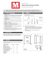
The Place ‘n PickTM Shelf Cart Kit System allows user to assemble a highly
versatile mobile shelving unit, equip it with bin boxes (not included) if desired,
then roll it where needed in the work area. Shelves may be adjusted for opti-
mum height and angle. Maximum rated capacity is 100 lbs per shelf. Cart is
available as complete kit, including three 12" deep x 30", 42", 54" or 66" wide
shelves (Model numbers HWP-SC30 [42] [54] [66]), or as cart frame only to fit
30", 42", 54" or 66" wide shelves or other accessories such as Bin Bar. Shelves
are not included with cart frame kits. Shelves and other accessories must be
ordered separately. See listing, page four.
NOTE: Prior to assembly, become familiar with the following instructions
and names of components as shown below.
ASSEMBLY INSTRUCTIONS
PLACE ‘n PICK
TM
SHELF CART
Printed in USA Bulletin No. 63039001.c
P.O. Box 26 • 600 South Clark St.
Mayville, WI 53050
Phone 920–387–5195
HUBBELL
®
Workplace Solutions
30.38", 42.38",
54.38", or 66.38"
LONG CROSS
MEMBER
CROSS MEMBER
ANGLE
BRACKET
SWIVEL CASTER
with WRENCH
48" LONG
UPRIGHT
29" LONG
LOWER SIDE
MEMBER
45OANGLE BRACE
BRACKET
45OANGLE
BRACE
BRACKET
45OALUMINUM
ANGLE BRACE
T-PLATE
T-PLATE
END
CAP
END
CAP
END
CAP
SHELVES WITH
TRAK CLAMP BARS
Standard kit includes three
30"W x 12"D shelves.
30", 42", 54" or 66" wide
shelves in either 12" or 18"
depth must be added to
frame kit with corresponding
width. Refer to components
list, page 4, or contact your
local Hubbell Workplace
Solutions distributor for more
information.
Figure 1.
COMPONENTS
T-PLATE
T-PLATE
IMPORTANT
ASSEMBLY NOTES
1. Components are assembled
using the Hubbell Workplace
Solutions “ALIGN – SET –
TIGHTEN” system; i.e. brackets
are clamped to aluminum
extrusions with track nuts inside
one of the two cavities.
Always install single bolt track
nuts with widest dimension
perpendicular to
aluminum rail.
2. All main frame
members are
extruded aluminum
rail. Install horizontal members
with large cavity down.
3. Shelves and all brackets are
steel and shipped with assembly
hardware (usually track nuts)
installed. Some track nuts may
have to be reversed (bolt head
on opposite side of plate) for
proper assembly.
END CAPS
END CAPS
10. Install casters with wrench included (Fig 9).
11. Install end caps and cover strip (Fig 10).
12. Check to make sure all bolts are tight and that unit
is square (all four casters firmly on floor).
Adjust as necessary.
Figure 10.
COMPLETED UNIT
COVER STRIP, optional
(Order model no. WA-CS20)
Cut to lengths required and
press into openings.
Figure 9
INSTALLING CASTERS
SWIVEL CASTER
WITH TRACK NUT
CASTER
WRENCH
COMPONENT LISTING
DESCRIPTION MODEL NO.
Complete Cart Kit-(3) 12"D x 30"W Shelves included . . . . .HWP-SC30
Complete Cart Kit-(3) 12"D x 42"W Shelves included . . . . .HWP-SC42
Complete Cart Kit-(3) 12"D x 54"W Shelves included . . . . .HWP-SC54
Complete Cart Kit-(3) 12"D x 66"W Shelves included . . . . .HWP-SC66
Frame Kit-For 30" Wide Shelves (Shelves NOT included) . .HWP-SC03
Frame Kit-For 42" Wide Shelves (Shelves NOT included) . .HWP-SC04
Frame Kit-For 54" Wide Shelves (Shelves NOT included) . .HWP-SC05
Frame Kit-For 66" Wide Shelves (Shelves NOT included) . .HWP-SC06
Shelf-12"D x 30"W . . . . . . . . . . . . . . . . . . . . . . . . . . . . . . .WS50-SS03
Shelf-12"D x 42"W . . . . . . . . . . . . . . . . . . . . . . . . . . . . . . .WS50-SS04
Shelf-12"D x 54"W . . . . . . . . . . . . . . . . . . . . . . . . . . . . . . .WS50-SS05
Shelf-12"D x 66"W . . . . . . . . . . . . . . . . . . . . . . . . . . . . . . .WS50-SS06
Shelf-18"D x 30"W . . . . . . . . . . . . . . . . . . . . . . . . . . . . . . .WS50-SS183
Shelf-18"D x 42"W . . . . . . . . . . . . . . . . . . . . . . . . . . . . . . .WS50-SS184
Shelf-18"D x 54"W . . . . . . . . . . . . . . . . . . . . . . . . . . . . . . .WS50-SS185
Shelf-18"D x 66"W . . . . . . . . . . . . . . . . . . . . . . . . . . . . . . .WS50-SS186
Bin Bar-36" (Fits 30"W Frame Kit) . . . . . . . . . . . . . . . . . . . .WS50-BB03A
Bin Bar-48" (Fits 42"W Frame Kit) . . . . . . . . . . . . . . . . . . . .WS50-BB04A
Bin Bar-60" (Fits 54"W Frame Kit) . . . . . . . . . . . . . . . . . . . .WS50-BB05A
Bin Bar-72" (Fits 66"W Frame Kit) . . . . . . . . . . . . . . . . . . . .WS50-BB06A
Cover Strip-20' long roll. Cut to length. . . . . . . . . . . . . . . . .WA-CS20

ASSEMBLY
1. Lay out all components. Locate shelves, casters,
and plastic end caps (Fig. 1) and set aside.
2. Locate two angle brackets and two T-plates. Place
two 29" aluminum frame members on floor with
large slot down. Affix angle brackets and T-plates
to side members by sliding track nuts into
aluminum rails. Position as shown in Figure 2,
and tighten track nuts to secure.
NOTE:
Position short (single bolt) track
nuts with long dimension running
across opening in aluminum rail.
3. Locate two 48" long uprights and two T-plates.
Affix T-plates to uprights as shown in Fig. 3.
Wrench tighten to secure.
NOTE:
“Right hand” and “Left hand” sub-assemblies
are required. Make side frames “mirror images”.
4. Assemble one upright to corresponding lower side
frame assembly by sliding onto angle bracket.
Tighten. Repeat for other side (Fig. 4).
8. Loosen clamp bars on shelf and Bin Bar (if used)
mounting brackets. Mount shelves and Bin Bar to
frame by sliding down from top with clamp bars
inside uprights (Fig 8). Refer to additional
instructions in Shelf or Bin Bar Kits. Position as
desired. Tighten securely.
9. Adjust shelves at desired angle(s). Refer to
instructions in Shelf Kits for more information.
6. Lay one side frame flat and slide two cross
members into T-plates. Slide cross members
tight against side frame members and securely
tighten track nut bolts (Fig 6).
7. Stand assembly upright and attach other side frame
(Fig 7). Square unit and securely tighten all bolts.
5. Assemble angle braces to frame lower side
members and uprights by simultaneously sliding one
45Obracket and angle brace into lower side member
and the other 45Obracket down into angle brace and
upright. Securely tighten all bolts (Fig. 5).
10.5"
15"
Figure 2.
ASSEMBLING LOWER SIDE MEMBERS
ANGLE
BRACKET
ANGLE
BRACKET
T-PLATES
LOWER SIDE FRAME
ASSEMBLY
ALL BRACKETS
MUST POINT
SAME DIREC-
TION ON EACH
SIDE FRAME
29" LONG
LOWER SIDE
MEMBERS
Figure 4.
ASSEMBLING UPRIGHTS TO LOWER SIDE MEMBERS
Figure 5.
INSTALLING ANGLE BRACES
Figure 8.
ATTACHING SHELVES
45OANGLE
BRACE
BRACKET
45OANGLE
BRACE
BRACKET
45OANGLE
BRACE
COMPLETED SIDE
FRAME ASSEMBLY
FROM STEP 4
Figure 6.
INSTALLING CROSS MEMBERS
Figure 7.
COMPLETING FRAME
ASSEMBLED SIDE
FRAME FROM STEP 5
ASSEMBLED
SIDE FRAME
FROM STEP 5
ASSEMBLED SIDE
FRAME WITH CROSS
MEMBERS FROM STEP 7
48" LONG
UPRIGHT
POSITION SHELVES
TO ACHIEVE
DESIRED HEIGHT
AND SPACING.
CLAMP BARS
BIN BAR (optional)
Designed to support
hanging bin boxes.
SHELF
T-PLATES
ALUMINUM CROSS MEMBERS.
ASSEMBLE WITH LARGE SLOT
DOWN WHERE APPLICABLE
COMPLETED
SIDE FRAME
ASSEMBLY
32"
Figure 3.
ASSEMBLING FRAME UPRIGHTS
T-PLATE
T-PLATE
48" LONG
UPRIGHTS
LOWER SIDE FRAME
ASSEMBLY
UPRIGHT
ASSEMBLY
UPRIGHT
ASSEMBLY
FRONT
FRONT
FRONT
BOTTOM
Position of T-plates (which affix cross
member) may have to be repositioned
when shelves are adjusted.

ASSEMBLY
1. Lay out all components. Locate shelves, casters,
and plastic end caps (Fig. 1) and set aside.
2. Locate two angle brackets and two T-plates. Place
two 29" aluminum frame members on floor with
large slot down. Affix angle brackets and T-plates
to side members by sliding track nuts into
aluminum rails. Position as shown in Figure 2,
and tighten track nuts to secure.
NOTE:
Position short (single bolt) track
nuts with long dimension running
across opening in aluminum rail.
3. Locate two 48" long uprights and two T-plates.
Affix T-plates to uprights as shown in Fig. 3.
Wrench tighten to secure.
NOTE:
“Right hand” and “Left hand” sub-assemblies
are required. Make side frames “mirror images”.
4. Assemble one upright to corresponding lower side
frame assembly by sliding onto angle bracket.
Tighten. Repeat for other side (Fig. 4).
8. Loosen clamp bars on shelf and Bin Bar (if used)
mounting brackets. Mount shelves and Bin Bar to
frame by sliding down from top with clamp bars
inside uprights (Fig 8). Refer to additional
instructions in Shelf or Bin Bar Kits. Position as
desired. Tighten securely.
9. Adjust shelves at desired angle(s). Refer to
instructions in Shelf Kits for more information.
6. Lay one side frame flat and slide two cross
members into T-plates. Slide cross members
tight against side frame members and securely
tighten track nut bolts (Fig 6).
7. Stand assembly upright and attach other side frame
(Fig 7). Square unit and securely tighten all bolts.
5. Assemble angle braces to frame lower side
members and uprights by simultaneously sliding one
45Obracket and angle brace into lower side member
and the other 45Obracket down into angle brace and
upright. Securely tighten all bolts (Fig. 5).
10.5"
15"
Figure 2.
ASSEMBLING LOWER SIDE MEMBERS
ANGLE
BRACKET
ANGLE
BRACKET
T-PLATES
LOWER SIDE FRAME
ASSEMBLY
ALL BRACKETS
MUST POINT
SAME DIREC-
TION ON EACH
SIDE FRAME
29" LONG
LOWER SIDE
MEMBERS
Figure 4.
ASSEMBLING UPRIGHTS TO LOWER SIDE MEMBERS
Figure 5.
INSTALLING ANGLE BRACES
Figure 8.
ATTACHING SHELVES
45OANGLE
BRACE
BRACKET
45OANGLE
BRACE
BRACKET
45OANGLE
BRACE
COMPLETED SIDE
FRAME ASSEMBLY
FROM STEP 4
Figure 6.
INSTALLING CROSS MEMBERS
Figure 7.
COMPLETING FRAME
ASSEMBLED SIDE
FRAME FROM STEP 5
ASSEMBLED
SIDE FRAME
FROM STEP 5
ASSEMBLED SIDE
FRAME WITH CROSS
MEMBERS FROM STEP 7
48" LONG
UPRIGHT
POSITION SHELVES
TO ACHIEVE
DESIRED HEIGHT
AND SPACING.
CLAMP BARS
BIN BAR (optional)
Designed to support
hanging bin boxes.
SHELF
T-PLATES
ALUMINUM CROSS MEMBERS.
ASSEMBLE WITH LARGE SLOT
DOWN WHERE APPLICABLE
COMPLETED
SIDE FRAME
ASSEMBLY
32"
Figure 3.
ASSEMBLING FRAME UPRIGHTS
T-PLATE
T-PLATE
48" LONG
UPRIGHTS
LOWER SIDE FRAME
ASSEMBLY
UPRIGHT
ASSEMBLY
UPRIGHT
ASSEMBLY
FRONT
FRONT
FRONT
BOTTOM
Position of T-plates (which affix cross
member) may have to be repositioned
when shelves are adjusted.

DESCRIPTION
The Place ‘n PickTM Shelf Cart Kit System allows user to assemble a highly
versatile mobile shelving unit, equip it with bin boxes (not included) if desired,
then roll it where needed in the work area. Shelves may be adjusted for opti-
mum height and angle. Maximum rated capacity is 100 lbs per shelf. Cart is
available as complete kit, including three 12" deep x 30", 42", 54" or 66" wide
shelves (Model numbers HWP-SC30 [42] [54] [66]), or as cart frame only to fit
30", 42", 54" or 66" wide shelves or other accessories such as Bin Bar. Shelves
are not included with cart frame kits. Shelves and other accessories must be
ordered separately. See listing, page four.
NOTE: Prior to assembly, become familiar with the following instructions
and names of components as shown below.
ASSEMBLY INSTRUCTIONS
PLACE ‘n PICK
TM
SHELF CART
Printed in USA Bulletin No. 63039001.c
600 South Clark St.
Mayville, WI 53050
Phone 920–387–4120
HUBBELL
®
Workplace Solutions
30.38", 42.38",
54.38", or 66.38"
LONG CROSS
MEMBER
CROSS MEMBER
ANGLE
BRACKET
SWIVEL CASTER
with WRENCH
48" LONG
UPRIGHT
29" LONG
LOWER SIDE
MEMBER
45OANGLE BRACE
BRACKET
45OANGLE
BRACE
BRACKET
45OALUMINUM
ANGLE BRACE
T-PLATE
T-PLATE
END
CAP
END
CAP
END
CAP
SHELVES WITH
TRAK CLAMP BARS
Standard kit includes three
30"W x 12"D shelves.
30", 42", 54" or 66" wide
shelves in either 12" or 18"
depth must be added to
frame kit with corresponding
width. Refer to components
list, page 4, or contact your
local Hubbell Workplace
Solutions distributor for more
information.
Figure 1.
COMPONENTS
T-PLATE
T-PLATE
IMPORTANT
ASSEMBLY NOTES
1. Components are assembled
using the Hubbell Workplace
Solutions “ALIGN – SET –
TIGHTEN”system; i.e. brackets
are clamped to aluminum
extrusions with track nuts inside
one of the two cavities.
Always install single bolt track
nuts with widest dimension
perpendicular to
aluminum rail.
2. All main frame
members are
extruded aluminum
rail. Install horizontal members
with large cavity down.
3. Shelves and all brackets are
steel and shipped with assembly
hardware (usually track nuts)
installed. Some track nuts may
have to be reversed (bolt head
on opposite side of plate) for
proper assembly.
END CAPS
END CAPS
10. Install casters with wrench included (Fig 9).
11. Install end caps and cover strip (Fig 10).
12. Check to make sure all bolts are tight and that unit
is square (all four casters firmly on floor).
Adjust as necessary.
Figure 10.
COMPLETED UNIT
COVER STRIP, optional
(Order model no. WA-CS20)
Cut to lengths required and
press into openings.
Figure 9
INSTALLING CASTERS
SWIVEL CASTER
WITH TRACK NUT
CASTER
WRENCH
COMPONENT LISTING
DESCRIPTION MODEL NO.
Complete Cart Kit-(3) 12"D x 30"W Shelves included . . . . .HWP-SC30
Complete Cart Kit-(3) 12"D x 42"W Shelves included . . . . .HWP-SC42
Complete Cart Kit-(3) 12"D x 54"W Shelves included . . . . .HWP-SC54
Complete Cart Kit-(3) 12"D x 66"W Shelves included . . . . .HWP-SC66
Frame Kit-For 30" Wide Shelves (Shelves NOT included) . .HWP-SC03
Frame Kit-For 42" Wide Shelves (Shelves NOT included) . .HWP-SC04
Frame Kit-For 54" Wide Shelves (Shelves NOT included) . .HWP-SC05
Frame Kit-For 66" Wide Shelves (Shelves NOT included) . .HWP-SC06
Shelf-12"D x 30"W . . . . . . . . . . . . . . . . . . . . . . . . . . . . . . .WS50-SS03
Shelf-12"D x 42"W . . . . . . . . . . . . . . . . . . . . . . . . . . . . . . .WS50-SS04
Shelf-12"D x 54"W . . . . . . . . . . . . . . . . . . . . . . . . . . . . . . .WS50-SS05
Shelf-12"D x 66"W . . . . . . . . . . . . . . . . . . . . . . . . . . . . . . .WS50-SS06
Shelf-18"D x 30"W . . . . . . . . . . . . . . . . . . . . . . . . . . . . . . .WS50-SS183
Shelf-18"D x 42"W . . . . . . . . . . . . . . . . . . . . . . . . . . . . . . .WS50-SS184
Shelf-18"D x 54"W . . . . . . . . . . . . . . . . . . . . . . . . . . . . . . .WS50-SS185
Shelf-18"D x 66"W . . . . . . . . . . . . . . . . . . . . . . . . . . . . . . .WS50-SS186
Bin Bar-36" (Fits 30"W Frame Kit) . . . . . . . . . . . . . . . . . . . .WS50-BB03A
Bin Bar-48" (Fits 42"W Frame Kit) . . . . . . . . . . . . . . . . . . . .WS50-BB04A
Bin Bar-60" (Fits 54"W Frame Kit) . . . . . . . . . . . . . . . . . . . .WS50-BB05A
Bin Bar-72" (Fits 66"W Frame Kit) . . . . . . . . . . . . . . . . . . . .WS50-BB06A
Cover Strip-20' long roll. Cut to length. . . . . . . . . . . . . . . . .WA-CS20
/