Page is loading ...

ANGLE BRACE BRACKET
and
17" ANGLE BRACE
Provides more rigidity than
Angle Bracket only. Do not
use without Angle Bracket
(above) or Corner Bracket
(shown here) to fully
triangulate structure.
FRAMING BRACKETS
RIGHT HAND & LEFT
HAND VERSIONS
USE: Perpendicular, non-
crossing track junction.
Often used to support rail
between uprights.
Punched and drilled to
accept standard electrical
boxes. Larger (1.1"dia.)
hole can also be used for
mounting of air line fitting
for pneumatic tools.
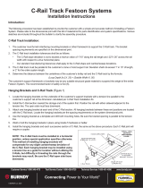
Extruded aluminum sections feature double tracks (top and bottom), one for trolleys and the other for mounting components or con-
cealing hose or cable. Inside dimensions of the larger section fits standard WS50 trolleys, brackets, stops, etc. In addition, there is a
full assortment of construction brackets, shown below, designed to fit either top or bottom track. Brackets slide into track from the end,
and clamp in place with track nuts. If more than one bracket is to be used in track section, they must be put into track in order. Brackets
cannot be inserted into center of track section. NOTE: Horizontal track must have a support hanger every 6.0 ft.(1.8m) to main-
tain rated capacity. Maximum rated capacity: 50 lbs.(22.5 Kg) when used as tool rail or other horizontal support.
2.35
(60)
0.55
(14)
1.62
(41)
HANGER DISK
USE: Join track sections
that cross at right angles.
Also hang rails from ceil-
ing, beams, other supports.
COVER STRIP
USE: Fills groove in track.
Keeps out dirt and debris,
improves appearance.
ANGLE BRACKET
USE: Join track sections at
right angles.
LEVELER FOOT
USE: Forms smooth foot at
bottom of track sections
used as legs. Adjust to
level structure by loosening
track nuts, repositioning
foot, and retightening nuts.
CORNER BRACKET
USE: Join three perpendicular track sections, usually
at corner of structure. Reverse track nuts as required.
TOP MOUNTING
BRACKET
USE: Attach top to bench-
es, tables, sound control
booths.
ANGLE MOUNTING
BRACKET
USE: Hang rail to wall or
other vertical support.
Also attach sound boards,
plywood, etc. to sides of
structures.
SPLICE ANGLE
USE: Allows precise join-
ing for unrestricted
trolley movement on long
track runs. See note
above regarding maximum
support spacing.
T–PLATE
USE: Perpendicular, non-
crossing track junction
(compare track orientation
to illustration above). Use
inside or outside of
structure. Install vertically
or horizontally.
Leg
outside Leg
inside
ASSEMBLY INSTRUCTIONS
ALUMINUM
TRACK
See EXAMPLES and
SUGGESTIONS, (over).
Wires or hoses
Aluminum Track,
section view
Balancer Trolley
rolling in track
Cover Strip

EXAMPLES and SUGGESTIONS
ALUMINUM TRACK
ASSEMBLY
Because of its unique versatility, aluminum
track and components are sold as individual
pieces, allowing you to design and build struc-
tures that best suit your needs. Shown here
are partially or fully assembled structures
which will (A) give you an indication of how the
various brackets work, and (B) provide ideas
for other uses for this structural/track system.
Pay special attention to bracket and track
section orientation.
1. Lay out pieces in order they will be
assembled. Note that brackets and other
components must be inserted into the
track “in order” because adding components
later may require partial disassembly.
2. To install brackets,
loosen bolts and
slide track nuts
into track sections.
NOTE: Orient
rectangular trak
nuts so widest
dimension lies across opening as shown
here. Position bracket in approximate
location, and tighten only enough to
temporarily hold bracket in position.
3. After all components are assembled,
set components in final position and
square-up assembly. Then, securely
tighten track nut bolts.
Slide hanger disks into
bottom section of sup-
port track (A), into top
section of tool rail (B)
Lower section shown
assembled for clarity.
Assemble using “slide in
place and tighten” tech-
nique shown above.
Sound enclosure uses Angle Mounting
Brackets and Top Mounting Brackets to
hold acoustical boards to sides and top.
Simple table or bench design features
post-and-lintel construction at corners
for maximum strength
Custom built conveyor support
features work surface in front and
two shelves above conveyor.
Framing Brackets and
cross piece may be insert-
ed in rearward facing track.
Use Angle Brackets to hold
horizontal supports (A) on
top of uprights (C).
Balancer trolley
along with stops
and end caps
may be inserted
into tool rail after
main components
are assembled.
Add Bin Bars, Power
Bars, Swing Arms or
other accessories during
assembly process.
A
A
C
B
Printed in USA Bulletin No. 630034.a
600 South Clark St.
Mayville, WI 53050
Phone 920–387–4120
HUBBELL
®
Trak
Nut
This Not This
Trak
Following assembly, double-check
to ensure all bolts are tight.
CAUTION
Workplace Solutions
/