Page is loading ...

www.TrailFX.com
Page 1 of 8 Rev 081217
Assistance Is Recommended. On Models with DEF Tank, Select A Flat, Level
Area For Installation
REMOVE CONTENTS FROM BOX. VERIFY ALL PARTS ARE PRESENT.
READ INSTRUCTIONS CAREFULLY BEFORE STARTING INSTALLATION.
DO NOT OVER TORQUE. STANDARD OPERATING LOAD FOR TIGHTEN
BODY MOUNT NUTS & BOLTS VARIES FROM 45 TO 65 FOOT POUND.
support@trailfx.com
1 866 638 4870
POLISHED STAINLESS STEEL – LIMITED LIFETIME
POWDER COATED BLACK – 3 YEARS
PARTS LIST:
Qty
Part Description
Qty
Part Description
1
Driver/left Side Step
17
8mm Lock Washers
1
Passenger/right Side Step
1
8mm Bolt Plate
1
Passenger/right Front Upper Bracket (all incl. DEF)
1
8mm Nylon Lock Nut (use w-bolt plate)
1
Passenger/right Front Lower Bracket (all incl. DEF)
8
6mm Double Bolt Plates
7
Mounting Brackets (use for left or right)
16
6mm Hex Nuts
15
8-1.25mm Clip-On Nuts
16
6mm Lock Washers
17
8-1.25mm x 25mm Hex Bolts
16
6mm x 22mm OD x 2mm Flat Washers
17
8mm x 24mm x 2mm Flat Washers
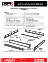
Rattler Steel Running Board
Part No. RBW03B
Fits: 2007-Current Chevrolet Silverado 1500/2500/3500 Crew Cab
2007-Current GMC Sierra 1500/2500/3500 Crew Cab
60-180 min
Drilling Not
Required
Cutting Is
Required
(4) Left or Right
Mounting Brackets
Passenger/right front
only Upper and Lower
Mounting Bracket
(8) 6mm Double Bolt Plates
(3) Left or Right
Mounting Brackets
8mm Double Bolt Plate
NOTE: Bottom of Running
Board illustrated to help
identify correct Running
Board
Front

www.TrailFX.com
Page 2 of 8 Rev 081217
INSTALLATION PROCEDURE:
REMOVE CONTENTS FROM BOX. VERIFY ALL PARTS ARE PRESENT. READ INSTRUCTIONS CAREFULLY
BEFORE STARTING INSTALLATION. ASSISTANCE IS RECOMMENDED. ON MODELS WITH DEF TANK, SELECT A
FLAT, LEVEL AREA FOR INSTALLATION.
1. Start the installation under the driver side of the vehicle. Locate the 5 tabs along the bottom edge of the body, (pinch weld).
Mounting Brackets will bolt to the 1st, 2nd, (just in front of center of cab), 4th and 5th mounting tabs, (Figure 1). Directly
above each tab is a top mounting location on the side of the body panel. Hold a Bracket up in place to help determine the
mounting holes to use along the body.
2. Determine the correct procedure for your model year and each Bracket location.
Bottom mounting location on the edge of the pinch weld.
Flat tab on pinch weld with factory installed weld nut:
Thread hex bolt into weld nut from the backside-down to clear paint from threads, (Figure 2).
Flat tab on pinch weld with hole:
Select (1) 8mm Clip Nut. Slide the Clip Nut over the tab with the nut facing up behind the tab, (Figures 3—6). Line
up threaded nut with hole in the tab. Repeat for each mounting location.
Locate top mounting location on the back side of the body panel.
Models with factory installed threaded insert in body panel:
Thread 8mm Hex Bolt into threaded insert to clear paint as required, (Figures 2 & 3).
Large and small hole in side of body panel:
Remove the rubber plug from the larger hole, (Figures 4 & 5). Select (1) 8mm Clip Nut. Slide the Clip Nut into the
larger hole. Line up the threaded nut with the smaller hole, (Figure 6).
3. Select (1) Mounting Bracket. NOTE: (5) Brackets are universal and will fit all left or center and rear right side. Bolt the
Mounting Bracket to the Clip Nuts and/or the factory threaded holes with (2) 8mm Hex Bolts, (2) 8mm Lock Washers and
(2) 8mm Flat Washers, (Figures 7 & 8). Do not tighten hardware.
4. Repeat Steps 1—3 to install the (3) remaining driver side Brackets, (Figure 11).
5. Select the driver/left Running Board. NOTE: Use the illustration on Page 1 to properly identify the driver side Running Board.
Place the Running Board on top of the Brackets. Locate the channels in the bottom of the Running Board. Select (4) 6mm
Double Bolt Plates, (Figure 9). Insert the Bolt Plates into the channels in the bottom of the Running Board closest to the
Brackets, (Figure 10). Lift the Running Board up and guide the studs through the Brackets.
6. Attach the Running Board to the Brackets with (8) 6mm Flat Washers, (8) 6mm Lock Washers and (8) 6mm Hex Nuts,
(Figures 11 & 24). NOTE: The Running Board is designed to fit close to the vehicle. It may be necessary to loosen the
Bracket hardware and tilt the Brackets downward to insert the Running Board between the Brackets and the body. Do not
tighten hardware at this time.
7. Level and adjust the Running Board and fully tighten all hardware.
8. Move to the passenger side of the vehicle. On the passenger side, determine if the vehicle is equipped with a plastic diesel
exhaust fluid (DEF) tank, (Figures 12 & 13).
Models without DEF tank, skip to Step 9.
Models with DEF tank: The tank sits close to the side of the body. With specialized tools, the passenger front upper and
lower Bracket can be installed but room is very limited. Determine model year of vehicle before proceeding.
Up to 2016 models:
It may be easier to drop the tank down to access the inner side of the body panel for upper bracket installation. Tank will
not need to be removed, only dropped down for access to mounting location. IMPORTANT: If tank is full, it will be very
heavy and assistance is highly recommended to avoid injury or damage to the vehicle or the tank. It is recommended that
installation is performed when the DEF tank is low on fluid before dropping the tank.
a. On models with plastic lower tray under the tank, remove the (3) hex bolts attaching the tray to the frame, (Figure
12), and remove the tray.
b. Release the tank filler hose. Release the plug for the sending unit on the top of the tank.

www.TrailFX.com
Page 3 of 8 Rev 081217
c. Support the tank with a floor jack. Place a smooth flat surface, (wooden block for example), between the floor jack
and the tank to avoid damaging the plastic tank. Do not push up on the tank; only support the weight of the tank
with the jack.
d. Remove the (2) bolts securing the tank straps to the vehicle, (Figure 13). Tilt the straps to release from the
brackets. Slowly lower the tank until the top of the tank is almost visible. Use blocks or stands to support the tank
while installing the front Upper and Lower Brackets.
e. Proceed to Step 9.
On 2017 models:
a. Remove the (4) hex bolts attaching plastic cover to DEF tank, (Figure 14A) and remove plastic cover, (Figure
14B). NOTE: On 2017 2500/3500 models, only remove plastic cover from DEF tank. Do not lower DEF tank and
proceed to Step 9.
9. Locate the first tab on the edge of the pinch weld, (Figures 2—5, 16 & 18). Select the Upper Bracket, (Figure 15). Repeat
Steps 2 & 3 to attach the passenger front Upper Bracket to the side of the body panel, (Figure 16). Do not tighten hardware
at this time.
10. Line up the hole in the bottom of the Upper Bracket with the hole in the tab on the pinch weld.
a. Models with a weld-nut: Slide the Bracket over the weld-nut, (Figure 16). Attach the Lower Bracket to the bottom
of the body and weld-nut with (1) 8mm x 25mm Hex Bolt, (1) 8mm Lock Washer and (1) 8mm Flat Washer, (Figures
19 & 24). Leave loose at this time.
b. Models with flat tab and hole: Insert the 8mm Bolt Plate down through the hole in the Upper Bracket and mounting
tab, (Figures 17 & 18). Attach the Lower Bracket to the bottom of the body and Bolt Plate with (1) 8mm Flat
Washer and (1) 8mm Nylon Lock Nut, (Figures 19 & 23). Leave loose at this time.
11. Line up the side tab on the Lower Bracket with the threaded hole in the side of the Upper Bracket. Attach the Lower Bracket
to the Upper Bracket with (1) 8mm x 25mm Hex Bolt, (1) 8mm Lock Washer and (1) 8mm Flat Washer, (Figure 24). Leave
loose at this time.
12. Repeat Steps 1—3 for the (3) remaining passenger side Bracket installations. NOTE: Cradles on Brackets installed on
passenger side will face forward.
a. 2017 2500/3500 DEF tank models: Locate the 2nd tab bracket location along the bottom edge of the body, (pinch
weld), (Figure 20). Hold the DEF cover in place and mark the location onto the cover, (Figure 21). Use a sharp
knife or hacksaw blade to carefully cut a slot in the plastic cover to clear the 2nd Bracket, (Figure 22). Remove as
little plastic as possible.
13. Repeat Steps 5—7 to install the passenger side Running Board.
14. Once the Running Board has been installed and all hardware fully tightened, reinstall the DEF tank and cover, if equipped,
as described in Steps 8 & 12.
15. Do periodic inspections to the installation to make sure that all hardware is secure and tight.
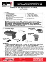
Front
(Fig 1) Driver side (4) mounting locations
(Fig 2) Passenger side front mounting location
8mm Weld Nut
Front
Factory 8mm threaded
insert in body panel

www.TrailFX.com
Page 4 of 8 Rev 081217
(Fig 3) Driver side 2nd mounting location
Front
Factory 8mm threaded
insert in body panel
8mm Clip Nut
(2) 8mm
Clip Nuts
(Fig 6) Driver side rear mounting location
Rear
(Fig 5) Driver side rear mounting location
Remove plug
Rear
(Fig 7) Driver/left front bracket installed
Front
(Fig 8) Driver/left rear bracket installed
(2) 8mm x 25mm Hex Bolts
(2) 8mm Lock Washers
(2) 8mm Flat Washers
Rear
(Fig 4) Driver side 3rd mounting location
Remove plug
Front

www.TrailFX.com
Page 5 of 8 Rev 081217
Driver/Left Side Installation Pictured
Front
(Fig 12) 07-16 Passenger side front
pictured with DEF tank cover. Remove
(3) hex bolts to remove cover
(Fig 14A) 2017 Passenger side pictured
with DEF plastic tank cover. Remove
(4) hex bolts to remove plastic cover
Front
(Fig 13) 07-16 Passenger side DEF tank and cover
Front
Remove (2) factory bolts
to remove tank straps
(Fig 11) Driver/left brackets installed
Front
(2) 8mm x 25mm Hex Bolts
(2) 8mm Lock Washers
(2) 8mm Flat Washers
(2) 6mm Flat Washers
(2) 6mm Lock Washers
(2) 6mm Hex Nuts
(Fig 9) 6mm Double Bolt Plate
(Fig 10) Slide Bolt Plates into
tracks under Running Board

www.TrailFX.com
Page 6 of 8 Rev 081217
Passenger Side/Right Installation Pictured
(Fig 15) Passenger/right Front
Upper Bracket (all models)
Front
(Fig 14B) 2017 Passenger side DEF cover
removed
Front
(Fig 17) 8mm x 35mm Bolt Plate
Front
8mm x 25mm Hex Bolt
8mm Lock Washer
8mm Flat Washer
(Fig 16) Slide Upper Bracket over weld
nut if equipped-also see Figure 2
Front
Fig 18
8mm Bolt Plate
On models with flat tab (see Fig 3 & 4),
insert 8mm Bolt Plate (Fig 16) down
through Upper Bracket and mounting tab
(Fig 19) Passenger/right Front
Lower Bracket (all models)
Front

www.TrailFX.com
Page 7 of 8 Rev 081217
Passenger Side/Right Installation Pictured
(Fig 22) 2017 Passenger side
DEF cut for example only
Front
(Fig 20) Passenger side 2nd and 3rd
bracket location from back of body
panel
Front
mark pictured is
approximately
70mm x 10mm
(Fig 21) 2017 Passenger side
DEF cover marked for trimming
(Fig 23) Passenger/right front Bracket installation
Front
On models with flat tab and 8mm Bolt
Plate (see Fig. 17) use:
8mm Flat Washer
8mm Nylon Lock Nut
to attach Lower Bracket to Bolt Plate
Models with weld nut on
tab (see Fig. 15) use:
8mm x 25mm Hex Bolt
8mm Lock Washer
8mm Flat Washer
(2) 6mm Flat Washers
(2) 6mm Lock Washers
(2) 6mm Hex Nuts
All models use:
8mm x 25mm Hex Bolt
8mm Lock Washer
8mm Flat Washer
Front
Fig 24
Complete Installation

www.TrailFX.com
Page 8 of 8 Rev 081217
FAQ’s
1. Hardware’s are not of correct size.
In GMC / Chevrolet truck model 2006 & up, customer needs to reuse the factory body bolts to install the bracket. If your vehicle is not GMC
/ Chevrolet 2006 & up, ensure that holes are not partially covered with any plastic grommet or rust? If it is, remove the plastic grommet &
rust from the thread holes & re-try the installation.
2. Mounting Bracket are not getting Installed properly.
In some cases Illustration images shown in Installation manual may not be the exactly same as per actual vehicle images ,also if Driver /
Passenger side mounting brackets are very identical in the design, suggest referring Parts Identification guide to avoid fitment issue.
3. Products are thumping / rattling after installation.
Ensure that all required mounting brackets / hardware’s are installed & tighten correctly. Suggest using white lithium / regular grease between
the metal to metal contact surfaces.
4. Side Bar is not aligning with vehicle / Step Pads are not aligning with vehicle doors.
Side bar may be interchanged or mounting brackets are not installed at the correct position in the vehicle. Refer Parts identification guide.
5. Missing / Excess Hardware.
Recheck hardware count as per the part list.
6. Product not installing properly.
Ensure make model year, cab length and bed size of your vehicle is listed in the application. All installation steps are followed correctly.
PARTS IDENTIFICATION GUIDE
Driver Side tube packed using “Green” color foam sheet. Passenger Side tube packed using “White” color foam sheet
No.
Parts Identification
1
Passenger / Right ‘Rear’ Bracket marked “PR”
2
Driver / Left ‘Rear’ Bracket marked “DR”
3
Passenger / Right ‘Center’ Bracket marked “PC”
4
Driver / Left ‘Center’ Bracket marked “DC”
5
Passenger / Right ‘Front’ Bracket marked “PF”
6
Driver / Left ‘Front’ Bracket marked “DF”
Note:
This guide is to identify the parts and not a reference for part count.
For part count, refer Parts List.
Product / Bracket image is representative and actual design may vary.
Check out these other TrailFX Products!! www.TrailFX.com
PRODUCT CARE
Periodically check the product to ensure all fasteners are tight and components are intact.
Regular waxing is recommended to protect the finish of the product.
Use ONLY Non-Abrasive automotive wax. Use of any soap, polish or wax that contains an abrasive is detrimental and can scratch the
finish leading to corrosion.
Aluminum polish may be used to polish small scratches and scuffs for Stainless Steel finish.
Mild soap may be used to clean the product for both Stainless Steel and Black finish.
Keystone Automotive Operations Inc. (KAO) warrants this product to be free of defects in material and workmanship at the time of purchase by the
original retail consumer. KAO disclaims any other warranties, express or implied, including the warranty of fitness for a particular purpose or an
intended use. If the product is found to be defective, KAO may replace or repair the product at our option, when the product is returned prepaid, with
proof of purchase. Alteration to, improper installation, or misuse of this product voids the warranty. KAO’s liability is limited to repair or replacement
of products found to be defective, and specifically excludes liability for any incidental or consequential loss or damage.
/