Canon i-SENSYS MF212w User manual
- Category
- Fax machines
- Type
- User manual
This manual is also suitable for

87654321
i-SENSYS MF229dw/MF226dn/MF217w/
MF216n/MF212w/MF211 Series
Service Manual Rev.1.0
Product Overview
Technical Overview
Periodical Services
Disassembly/Assembly
Adjustment
Trouble Shooting
Error Codes
Service Mode
Appendix

0
0
0-2
0-2
Application
This manual has been issued by Canon Inc. for qualied persons to learn technical theory,
installation, maintenance, and repair of products. This manual covers all localities where the
products are sold. For this reason, there may be information in this manual that does not
apply to your locality.
Corrections
This manual may contain technical inaccuracies or typographical errors due to improvements
or changes in products. When changes occur in applicable products or in the contents of this
manual, Canon will release technical information as the need arises. In the event of major
changes in the contents of this manual over a long or short period, Canon will issue a new
edition of this manual.
The following paragraph does not apply to any countries where such provisions are
inconsistent with local law.
Trademarks
The product names and company names used in this manual are the registered trademarks
of the individual companies.
Copyright
This manual is copyrighted with all rights reserved. Under the copyright laws, this manual may
not be copied, reproduced or translated into another language, in whole or in part, without the
consent of Canon Inc.
Copyright CANON INC. 2014
Caution
Use of this manual should be strictly supervised to avoid disclosure of condential
information.

0
0
0-3
0-3
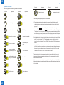
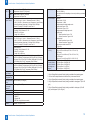
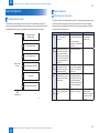
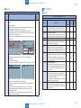
Explanation of Symbols
The following symbols are used throughout this Service Manual.
Symbols Explanation Symbols Explanation
Check.
1x
Remove the claw.
Check visually.
1x
Insert the claw.
Check a sound. Push the part.
1x
Disconnect the connector. Connect the power cable.
1x
Connect the connector.
Disconnect the power
cable.
1x
Remove the cable/wire
from the cable guide or wire
saddle.
Turn on the power.
1x
Install the cable/wire to the
cable guide or wire saddle.
Turn off the power.
1x
Remove the screw.
1x
Loosen the screw.
1x
Install the screw.
1x
Tighten the screw.
Symbols Explanation Symbols Explanation
Cleaning is needed. Measurement is needed.
The following rules apply throughout this Service Manual:
1. Each chapter contains sections explaining the purpose of specic functions and the
relationship between electrical and mechanical systems with reference to the timing of
operation.
In the diagrams, represents the path of mechanical drive; where a signal name
accompanies the symbol, the arrow
indicates the direction of the electric signal.
The expression "turn on the power" means ipping on the power switch, closing the front
door, and closing the delivery unit door, which results in supplying the machine with power.
2. In the digital circuits, '1' is used to indicate that the voltage level of a given signal is "High",
while '0' is used to indicate "Low". (The voltage value, however, differs from circuit to
circuit.) In addition, the asterisk (*) as in "DRMD*" indicates that the DRMD signal goes on
when '0'.
In practically all cases, the internal mechanisms of a microprocessor cannot be checked
in the eld. Therefore, the operations of the microprocessors used in the machines are not
discussed: they are explained in terms of from sensors to the input of the DC controller
PCB and from the output of the DC controller PCB to the loads.
The descriptions in this Service Manual are subject to change without notice for product
improvement or other purposes, and major changes will be communicated in the form of
Service Information bulletins.
All service persons are expected to have a good understanding of the contents of this Service
Manual and all relevant Service Information bulletins and be able to identify and isolate faults
in the machine.

0
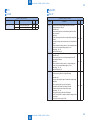
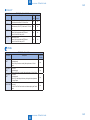
Safety Precautions
CDRH Provisions -------------------------------------------------------------0-2
Laser Safety
--------------------------------------------------------------------0-2
About Laser Beams --------------------------------------------------------------- 0-2
Handling Laser Scanner Unit --------------------------------------------------- 0-2
Toner Safety --------------------------------------------------------------------0-3
About Toner ------------------------------------------------------------------------- 0-3
Handling Adhered Toner --------------------------------------------------------- 0-3
Notes on Handling Lithium Battery ---------------------------------------0-3
Notes on Assembly/Disassembly
-----------------------------------------0-3
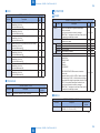
1
Product Overview
Product Lineups ---------------------------------------------------------------1-2
Main Unit ----------------------------------------------------------------------------- 1-2
Options ------------------------------------------------------------------------------- 1-2
Manufacture Sketch Drawing ----------------------------------------------1-3
Features
-------------------------------------------------------------------------1-4
Features ------------------------------------------------------------------------------ 1-4
Product Specications -------------------------------------------------------1-4
Main Unit Specications ---------------------------------------------------------- 1-4
Wireless LAN Specications ---------------------------------------------------- 1-6
SADF/DADF Specications ----------------------------------------------------- 1-6
FAX Specications(FAX model Only) ----------------------------------------- 1-7
Name of Parts ------------------------------------------------------------------1-8
External View ----------------------------------------------------------------------- 1-8
Cross Section ---------------------------------------------------------------------- 1-11
Control Panel ----------------------------------------------------------------------1-13
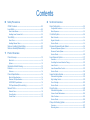
Contents
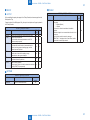
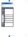
2
Technical Overview
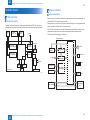
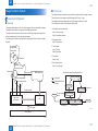
Basic Conguration -----------------------------------------------------------2-2
Conguration function ------------------------------------------------------------ 2-2
Basic Sequence -------------------------------------------------------------------- 2-2
Controller System -------------------------------------------------------------2-4
Main Controller --------------------------------------------------------------------- 2-4
Engine Controller ------------------------------------------------------------------ 2-4
Service Works ---------------------------------------------------------------------- 2-5
Document Exposure/Feeder System ------------------------------------2-6
Document Exposure System ---------------------------------------------------- 2-6
Document Feeder System ------------------------------------------------------- 2-7
Service Works ---------------------------------------------------------------------2-10
Laser Exposure System --------------------------------------------------- 2-11
Overview ---------------------------------------------------------------------------- 2-11
Controlling the Laser Activation Timing --------------------------------------2-12
Laser Control -----------------------------------------------------------------------2-13
Laser Scanner Motor Control --------------------------------------------------2-13
Service Works ---------------------------------------------------------------------2-14
Image Formation System ------------------------------------------------- 2-15
Overview/Conguration ---------------------------------------------------------2-15
High-Voltage Control -------------------------------------------------------------2-19
Toner Cartridge --------------------------------------------------------------------2-20
Service Works ---------------------------------------------------------------------2-22
Fixing System ---------------------------------------------------------------- 2-23
Overview/Conguration ---------------------------------------------------------2-23
Various Control Mechanisms --------------------------------------------------2-24
Other Functions -------------------------------------------------------------------2-25
Service Works ---------------------------------------------------------------------2-26
Pickup And Feeding System --------------------------------------------- 2-27
Overview ----------------------------------------------------------------------------2-27
Detecting Jams --------------------------------------------------------------------2-28

Reversal Delay Jam --------------------------------------------------------------2-30
Service Works ---------------------------------------------------------------------2-33
External And Controls System ------------------------------------------- 2-34
Power Supply ----------------------------------------------------------------------2-34
Service Works ---------------------------------------------------------------------2-35
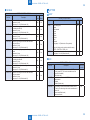
3
Periodical Services
Periodically Replaced Parts ------------------------------------------------3-2
Periodically Replaced Parts ----------------------------------------------------- 3-2
Consumables ------------------------------------------------------------------3-2
Consumables ----------------------------------------------------------------------- 3-2
Periodical Service -------------------------------------------------------------3-3
Scheduled Servicing -------------------------------------------------------------- 3-3
4
Disassembly/Assembly
Outline ---------------------------------------------------------------------------4-3
List of Parts
---------------------------------------------------------------------4-4
External View ----------------------------------------------------------------------- 4-4
List of Main Unit
-------------------------------------------------------------------- 4-7
Electrical Components -----------------------------------------------------------4-10
Connectors Layout Drawing ---------------------------------------------- 4-19
DADF Unit and Reader Unit ----------------------------------------------------4-19
SADF Unit and Reader Unit ----------------------------------------------------4-20
Copyboard Unit and Reader Unit ---------------------------------------------4-21
Duplex Printer Unit ---------------------------------------------------------------4-22
Sinplex Printer Unit ---------------------------------------------------------------4-25
Original Exposure/Feed System (DADF Model) -------------------- 4-27
Layout Drawing --------------------------------------------------------------------4-27
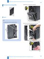
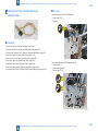
Removing the DADF Unit + Reader Unit -----------------------------------4-27
Disconnecting the DADF Unit + Reader Unit ------------------------------4-30
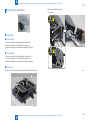
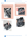
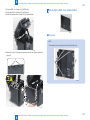
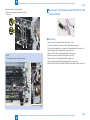
Removing the DADF Pickup Unit ---------------------------------------------4-32
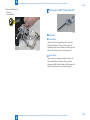
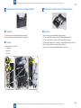
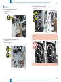
Removing the DADF Motor Unit ----------------------------------------------4-36
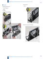
Removing the DADF Solenoid Unit ------------------------------------------4-38
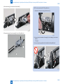
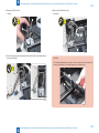
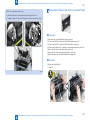
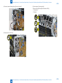
Removing the DADF Pickup Roller Unit ------------------------------------4-39
Removing the DADF Separation Pad ----------------------------------------4-41
Removing the Copyboard Glass (DADF Model) --------------------------4-44
Removing the Contact Image Sensor (DADF Model)
-------------------4-46
Removing the Flat Bed Motor Unit (DADF Model) -----------------------4-48
Original Exposure/Feed System (SADF Model) --------------------- 4-51
Layout Drawing --------------------------------------------------------------------4-51
Removing the SADF Unit + Reader Unit. -----------------------------------4-51
Disconnecting the SADF Unit and the Reader Unit ----------------------4-54
Removing the SADF Upper Cover Unit -------------------------------------4-56
Removing the SADF Pickup Unit ---------------------------------------------4-60
Removing the SADF Motor -----------------------------------------------------4-61
Removing the SADF Pickup Roller Unit -------------------------------------4-62
Removing the SADF Separation Pad ----------------------------------------4-65
Removing the Copyboard Glass (SADF Model) --------------------------4-68
Removing the Contact Image Sensor (SADF Model)--------------------4-70
Removing the Flat Bed Motor Unit (SADF Model)------------------------4-72
Original Exposure/Feed System (Copyboard Model) -------------- 4-75
Layout Drawing --------------------------------------------------------------------4-75
Removing the Copyboard Cover ----------------------------------------------4-75
Removing the Copyboard Cover + Reader Unit --------------------------4-76
Removing the Copyboard Glass (Copyboard Model)--------------------4-78
Removing the Contact Image Sensor (Copyboard Model) -------------4-80
Removing the Flat Bed Motor Unit (Copyboard Model) -----------------4-82
External Cover/Internal System (Duplex Model) -------------------- 4-85
Layout Drawing --------------------------------------------------------------------4-85
Removing the Left Cover (Duplex Model) ----------------------------------4-86
Removing the Right Cover (Duplex Model) --------------------------------4-87
Removing the Front Cover Unit (Duplex Model) --------------------------4-89
Removing the Upper Cover Unit (Duplex Model) -------------------------4-89
Removing the Duplex Feed Guide Unit. (Duplex Model) ---------------4-91
Controller System (Duplex Model) -------------------------------------- 4-93
Layout Drawing --------------------------------------------------------------------4-93
Removing the Control Panel Unit (Duplex Model) ------------------------4-93
Removing the Main Motor (Duplex Model) ---------------------------------4-95
Removing the Main Fan (Duplex Model) ------------------------------------4-97
Removing the Edge Left Cooling Fan (Duplex Model) ------------------4-99
Removing the Edge Right Cooling Fan (Duplex Model) -------------- 4-101
Removing the Engine Controller PCB (Duplex Model) ---------------- 4-102

Removing the Main Controller PCB (Duplex Model) ------------------- 4-105
Removing the FAX NCU PCB
(Fax Model 120V/230V) (Duplex Model) ---------------------------------- 4-107
Removing the Wirelss LAN PCB (Wi Model + Duplex Model) ----- 4-108
Removing the Paper Leading Edge Sensor PCB (Duplex Model) - 4-108
Removing the Fixing Delivery/Paper Width Sensor PCB
(Duplex Model) -------------------------------------------------------------------4-111
Removing the Toner Sensor and Multi Pickup Sensor Unit
(Fax Model + Duplex Model) ------------------------------------------------- 4-114
Removing the Speaker (Fax Model + Duplex Model) ----------------- 4-116
Laser Exposure System (Duplex Model) -----------------------------4-118
Layout Drawing ------------------------------------------------------------------ 4-118
Removing the Laser Scanner Unit (Duplex Model) -------------------- 4-118
Image Formation System (Duplex Model) -------------------------- 4-120
Layout Drawing ------------------------------------------------------------------ 4-120
Removing the Transfer Roller (Duplex Model) -------------------------- 4-120
Fixing System (Duplex Model) ----------------------------------------- 4-122
Layout Drawing ------------------------------------------------------------------ 4-122
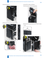
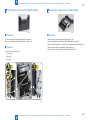
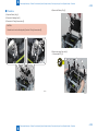
Removing the Fixing Assembly (Duplex Model) ------------------------ 4-122
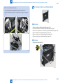
Pickup Feed System (Duplex Model) -------------------------------- 4-127
Layout Drawing ------------------------------------------------------------------ 4-127
Removing the Pickup Unit (Duplex Model) ------------------------------- 4-127
Removing the Pickup Tray Unit (Duplex Model) ------------------------ 4-132
Removing the Pickup Roller (Duplex Model) ---------------------------- 4-134
Removing the Separation Pad (Duplex Model) ------------------------- 4-135
Removing the Delivery Slave Roller Unit (Duplex Model) ------------ 4-136
Removing the Pickup Solenoid (Duplex Model)------------------------- 4-137
Removing the Duplex Solenoid (Duplex Model) ------------------------ 4-141
External Cover/Internal System (Simplex Model) ----------------- 4-143
Layout Drawing ------------------------------------------------------------------ 4-143
Removing the Left Cover (Simplex Model) ------------------------------- 4-144
Removing the Right Cover (Simplex Model) ----------------------------- 4-145
Removing the Front Cover Unit (Simplex Model) ----------------------- 4-147
Removing the Upper Cover (Simplex Model) ---------------------------- 4-147
Removing the Rear Cover (Simplex Model) ----------------------------- 4-149
Controller System (Simplex Model) ---------------------------------- 4-151
Layout Drawing ------------------------------------------------------------------ 4-151
Removing the Control Panel Unit (Simplex Model) -------------------- 4-151
Removing the Main Motor (Simplex Model) ------------------------------ 4-153
Removing the Engine Controller PCB (Simplex Model)--------------- 4-155
Removing the Main Controller PCB (Simplex Model) ----------------- 4-159
Removing the FAX NCU PCB
(Fax Model 120V/230V + Simplex Model) -------------------------------- 4-161
Removing the Wireless LAN PCB (Wi Model + Simplex Model) -- 4-161
Removing the Paper Leading Edge Sensor (Simplex Model) ------- 4-162
Removing the Fixing Delivery/Paper Width Sensor PCB
(Simplex Model) ----------------------------------------------------------------- 4-164
Removing the Toner Sensor and Multi Pickup Sensor Unit
(Fax Model + Simplex Model) ----------------------------------------------- 4-167
Removing the Speaker (Fax Model + Simplex Model) ---------------- 4-169
Laser Exposure System (Simplex Model) -------------------------- 4-171
Layout Drawing ------------------------------------------------------------------ 4-171
Removing the Laser Scanner Unit (Simplex Model) ------------------- 4-171
Image Formation System (Simplex Model) ------------------------- 4-173
Layout Drawing ------------------------------------------------------------------ 4-173
Removing the Transfer Roller (Simplex Model) ------------------------- 4-173
Fixing System (Simplex Model) --------------------------------------- 4-175
Layout Drawing ------------------------------------------------------------------ 4-175
Removing the Fixing Assembly (Simplex Model) ----------------------- 4-175
Pickup Feed System (Simplex Model) ------------------------------- 4-180
Layout Drawing ------------------------------------------------------------------ 4-180
Removing the Pickup Unit (Simplex Model) ------------------------------ 4-180
Removing the Pickup Tray Unit (Simplex Model) ----------------------- 4-184
Removing the Pickup Roller (Simplex Model) --------------------------- 4-186
Removing the Separation Pad (Simplex Model) ------------------------ 4-187
Removing the Delivery Slave Roller Unit (Simplex Model) ----------- 4-188
Removing the Pickup Solenoid (Simplex Model) ----------------------- 4-190

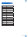
5
Adjustment
Mechanical Adjustment ------------------------------------------------------5-2
Conrming Nip Width ------------------------------------------------------------- 5-2
6
Trouble Shooting
Test Print ------------------------------------------------------------------------6-2
Test Print Function ----------------------------------------------------------------- 6-2
Trouble Shooting Items ------------------------------------------------------6-3
Image Faults ------------------------------------------------------------------------ 6-3
Log Collector -------------------------------------------------------------------6-8
OutLine ------------------------------------------------------------------------------- 6-8
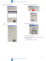
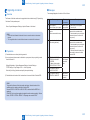
Version Upgrade ------------------------------------------------------------ 6-10
Overview ----------------------------------------------------------------------------6-10
UST -----------------------------------------------------------------------------------6-10
Preparation -------------------------------------------------------------------------6-10
Downloading System Software ------------------------------------------------ 6-11
Upgrading via Internet -----------------------------------------------------------6-13
7
Error Codes
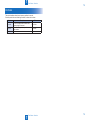
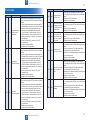
Overview ------------------------------------------------------------------------7-2
Error Codes
---------------------------------------------------------------------7-3
Jam Codes
----------------------------------------------------------------------7-4
8
Service Mode
Overview ------------------------------------------------------------------------8-2
Entering Service Mode. ---------------------------------------------------------- 8-2
Service Mode Menu --------------------------------------------------------------- 8-2
COPIER -------------------------------------------------------------------------8-4
DISPLAY ----------------------------------------------------------------------------- 8-4
I/O -------------------------------------------------------------------------------------- 8-5
ADJUST ------------------------------------------------------------------------------ 8-5
FUNCTION -------------------------------------------------------------------------- 8-6
OPTION ------------------------------------------------------------------------------ 8-8
COUNTER --------------------------------------------------------------------------- 8-9
FEEDER ----------------------------------------------------------------------- 8-11
ADJUST ----------------------------------------------------------------------------- 8-11
FUNCTION ------------------------------------------------------------------------- 8-11
FAX ----------------------------------------------------------------------------- 8-12
List of SSSW -----------------------------------------------------------------------8-12
List of MENU -----------------------------------------------------------------------8-14
List of NUM -------------------------------------------------------------------------8-15
List of NCU -------------------------------------------------------------------------8-16
TESTMODE ------------------------------------------------------------------ 8-20
SYSTEM ----------------------------------------------------------------------------8-20
SCAN --------------------------------------------------------------------------------8-20
FAX -----------------------------------------------------------------------------------8-21
PANEL -------------------------------------------------------------------------------8-22
NETWORK ------------------------------------------------------------------- 8-23
SSSW --------------------------------------------------------------------------------8-23
Appendix
Service Tools -------------------------------------------------------------------9-2
Solvent/Oil List
-----------------------------------------------------------------9-3
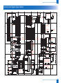
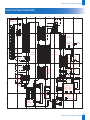
General Circuit Diagram (Duplex Model)
-------------------------------9-4
General Circuit Diagram (Simplex Model)
------------------------------9-5
General Timing Chart
--------------------------------------------------------9-6
List of User Mode
-------------------------------------------------------------9-7
Network Settings ------------------------------------------------------------------- 9-7
Preferences ------------------------------------------------------------------------- 9-8
Quiet Mode Time ------------------------------------------------------------------- 9-9
Common Settings ------------------------------------------------------------------ 9-9
Copy Settings ----------------------------------------------------------------------- 9-9
Fax Settings ------------------------------------------------------------------------- 9-9
Scan Settings ----------------------------------------------------------------------9-10
Printer Settings --------------------------------------------------------------------9-10
Adjustment/Maintenance --------------------------------------------------------9-10
System Management Settings -------------------------------------------------9-10
Backup Data ------------------------------------------------------------------ 9-12


0
0
0-2
0-2
Safety Precautions > Laser Safety > Handling Laser Scanner Unit
Safety Precautions > Laser Safety > Handling Laser Scanner Unit
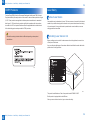
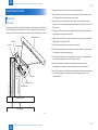
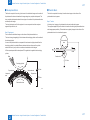
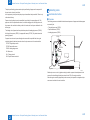
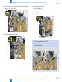
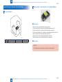
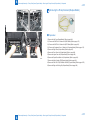
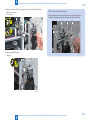
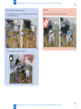
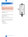
CDRH Provisions
Food and Drug CDRH (Center for Devices and Radiological Health) under FDA (Food and
Drug Administration) enforced provisions of the section for laser and laser products on August
2, 1976. These provisions are applicable to all laser products manufactured or assembled
after August 1, 1976 and allow only products certied their compliance with the provisions
to market in the US. Each product shall have afxed the applicable label as shown below to
follow the labeling requirements prescribed in CDRH provisions.
Note that the wording included in labels is different depending on laser product
classications.
F-0-1
Laser Safety
About Laser Beams
Laser radiation may be hazardous to human. The laser scanner unit mounted in this device is
sealed in the protective housing and the external cover to prevent laser beams from leaking
to the environment. As long as the device is operated under normal conditions, users are
safely guarded from laser leaks.
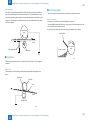
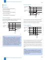
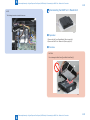
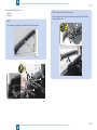
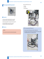
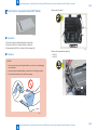
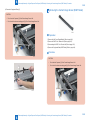
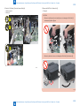
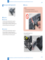
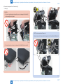
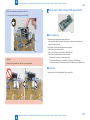
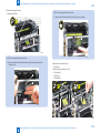
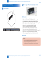
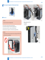
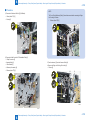
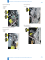
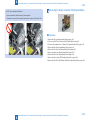
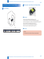
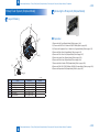
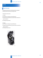
Handling Laser Scanner Unit
Before providing service works for the laser scanner unit and its peripherals, ensure to turn
off the power of the device.
Any cover with potential dangers of laser beam reection has afxed the caution label at the
position shown in the gure below.
This product is certicated as a Class 1 laser product under IEC60825-1:2007.
But this product is equipped with a class 3B laser.
When you remove interlock and work, you must warn the safety.
F-0-2

0
0
0-3
0-3
Safety Precautions > Notes on Assembly/Disassembly
Safety Precautions > Notes on Assembly/Disassembly
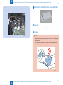
Toner Safety
About Toner
Toner is a nontoxic matter composed of plastic, iron and a trace of pigments.
Never throw toner in ames to avoid explosion.
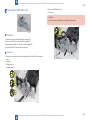
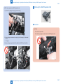
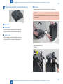
Handling Adhered Toner
• Use dry tissue paper to wipe off toner adhered to skin or clothes and wash in water.
• Never use warm water for cleaning up toner to prevent toner particles from being able to
soak into bers permanently.
• Toner particles are reactive with vinyl polymers. Avoid contacting these materials.
Notes on Handling Lithium Battery
Replacing with wrong battery types may cause explosion.
Follow instructions to dispose used batteries properly.
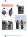
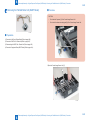
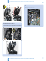
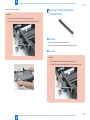
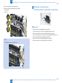
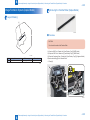
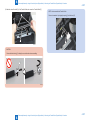
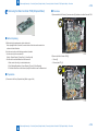
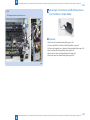
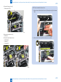
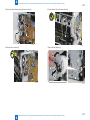
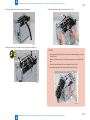
Notes on Assembly/Disassembly
Follow the items below to assemble/disassemble the device.
1. Disconnect the power plug to avoid any potential dangers during assembling/disassembling
works.
2. If not specially instructed, reverse the order of disassembly to reinstall.
3. Ensure to use the right screw type (length, diameter, etc.) at the right position when
assembling.
4. To keep electric conduction, binding screws with washers are used to attach the grounding
wire and the varistor. Ensure to use the right screw type when assembling.
5. Unless it is specially needed, do not operate the device with some parts removed.
6. Never remove the paint-locked screws when disassembling.


1
1
1-2
1-2
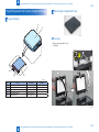
Product Overview > Product Lineups > Options
Product Overview > Product Lineups > Options
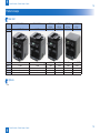
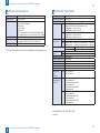
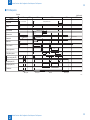
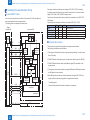
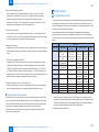
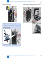
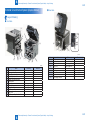
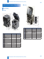
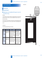
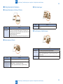
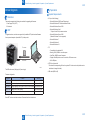
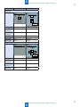
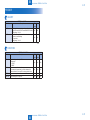
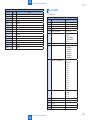
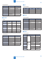
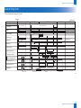
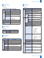
Product Lineups
Main Unit
Model i-SENSYS MF229dw i-SENSYS MF226dn i-SENSYS
MF217w
i-SENSYS
MF216n
i-SENSYS
MF212w
i-SENSYS
MF211
Cong 4in1DADF+WN 4in1SADF+N 4in1SADF+WN 4in1SADF+N 3in1Pla+WN 3in1Pla
Design
ADF DADF SADF SADF SADF PLATEN PLATEN
Engine 2-Sided 2-Sided 1-Sided 1-Sided 1-Sided 1-Sided
LAN port Yes Yes Yes Yes Yes
Wireless LAN Yes Yes Yes
FAX Yes Yes Yes Yes
Options
• Non
F-1-1
F-1-2
F-1-3
F-1-4
T-1-1

1
1
1-3
1-3
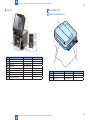
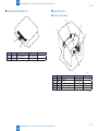
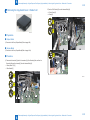
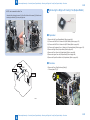
Product Overview > Manufacture Sketch Drawing
Product Overview > Manufacture Sketch Drawing
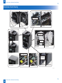
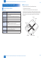
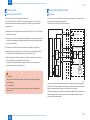
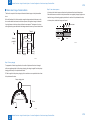
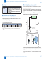
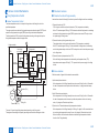
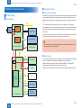
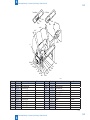
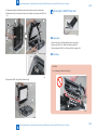
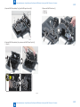
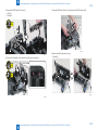
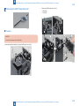
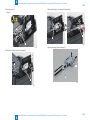
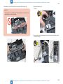
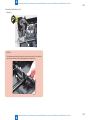
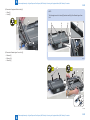
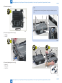
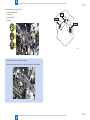
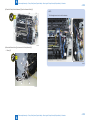
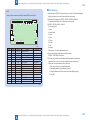
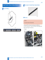
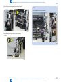
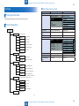
Manufacture Sketch Drawing
Duplex Model Sinplex Model
Duplex Model Sinplex Model
Duplex Model Sinplex Model
Duplex Model
Duplex Model
Sinplex Model
Sinplex Model
DADF Model
SADF Model
Copyboard Model
Edge Cooling Fan
Duplex Solenoid
Main Fan
Duplex Relay PCB
Intake hole of
the main fan
F-1-5

1
1
1-4
1-4
Product Overview > Product Specications > Main Unit Specications
Product Overview > Product Specications > Main Unit Specications
Features
Features
1. Small-size, high-speed monochrome printer
This equipment has a compact body that realizes high-speed print of 27 ppm (A4) / 26 ppm
(LTR).
2. Automatic duplex print
Automatic two-sided printing is available with standard equipped duplex unit.
3. Reduction in standby time and energy consumption
This equipment employs on-demand xing where the heater activates only during printing,
resulting in a reduction in standby time and energy consumption on this mode.
4. Realization of noise reduction and stable image quality
This equipment employs a belt drive method for transmitting the drive of the main motor.
This enables lower noise and more stable image quality compared to the conventional gear
drive method. (See NOTE)
5. Improved Usability
In this equipment maintenance (jam removal, replacing the cartridge) can be performed by
accessing one point of the delivery tray.
Note:
Changing the drive method from gear to belt reduces uneven pitch due to varied
rotation speed of the photosensitive drum, which realizes stable image quality.
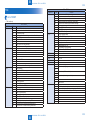
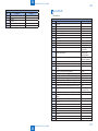
Product Specications
Main Unit Specications
Copyboard Fixed
Device Installation Personal Desktop
Light source LED (RGB)
Image scanning CIS (color)
Photoreceptor OPC drum (φ24)
Light exposure
method
Laser beam exposure (semiconductor laser)
Charging method Roller charging
Developing method Toner projection developing method
Transfer method Direct transfer to the transfer member
Separation method Curvature separation
Paper feed method Pickup Tray : Semilunar-shaped Pickup Roller + Pad separation method
(pressure release mechanism is not available)
Multi-purpose Tray : Semilunar-shaped Pickup Roller + Pad separation
method (pressure release mechanism is not available)
Paper delivery
method
Face-down
Drum cleaning
method
Cleaning blade
Fixing method SURF xing method with the Ceramic Heater
Toner supply method All-in-one cartridge with drum
Toner level sensor Fax model: Yes (magnetic sensor)
Document types Sheets, Book, Height of document : 20 mm, Weight: up to 2 Kg
Maximum document
size
Fixation : to A4
ADF : to LGL
Image size
magnication
100% Direct, 400% Max, 200%, 129% STMT->LTR, 78% LGL->LTR, 64%
LTR->STMT, 50%, 25% Min
Zoom Zoom : 25 to 400 % (1 % increment)
Reading resolution Text/photo : 300 dpi x 300 dpi (default)
Text/photo : 600 dpi x 600 dpi
Text : 600 dpi x 600 dpi
Photo : 600 dpi x 600 dpi
Print resolution 1,200 dpi equivalent x 1,200 dpi equivalent
Warm-up Time 13.5 seconds or less
First print time 6.0 seconds or less
First copy time
• Platen glass: 9 seconds or less
• Feeder: 14 seconds or less
Print
Speed
Simplex
Print
Duplex Model: 28 ppm(LTR), 27 ppm(A4)
Simplex Model: 24 ppm(LTR), 23 ppm(A4)
Duplex
Print
Duplex Model: 16 cpm(LTR), 15 cpm(A4)
Simplex Model: Non Duplex Print

1
1
1-5
1-5
Product Overview > Product Specications > Main Unit Specications
Product Overview > Product Specications > Main Unit Specications
Copy
speed
Simplex
Print
Duplex Model: 28 ppm(LTR), 27 ppm(A4)
Simplex Model: 24 ppm(LTR), 23 ppm(A4)
Duplex
Print
Duplex Model: 16 cpm(LTR), 15 cpm(A4)
Simplex Model: Non Duplex Print
Available paper size
in Paper Cassette
Fixed size :
A4 *1 , B5, A5, Legal *1, Letter *1 , Statement, Executive *1, Ofcio *1,
B-ofcio *1, M-ofcio *1, Government - Letter, Government - Legal, Foolscap
*1, Australian-foolscap, Indian-Legal *1, Envelope COM10, Envelope
Monarch *2, Envelope C5, Envelope DL, Index Card *2
Custom paper size :
• Envelope: COM10 / Monarch / C5 / DL
• Width: 76.2 to 216.0 mm
• Length: 148.0 to 356.0 mm
Available paper size
in multi-purpose tray
Fixed size :
A4 *1 , B5, A5, Legal *1, Letter *1 , Statement, Executive *1, Ofcio *1,
B-ofcio *1, M-ofcio *1, Government - Letter, Government - Legal, Foolscap
*1, Australian-foolscap, Indian-Legal *1, Envelope COM10, Envelope
Monarch *2, Envelope C5, Envelope DL, Index Card *2
Custom paper size :
• Envelope: COM10 / Monarch / C5 / DL
• Width: 76.2 to 216.0 mm
• Length: 148.0 to 356.0 mm
Paper types for Paper
Cassette
Plain paper*3 (60 to 90 g/m²(16 to 24 lb Bond )), Heavy paper*4 (90 to 163
g/m²(24 to 60 lb Bond)), Recycled paper*3 (60 to 90 g/m²(16 to 24 lb Bond)),
Color paper*3 (60 to 90 g/m²(16 to 24 lb Bond)), Bond paper*5 (60 to 163 g/
m²(16 lb Bond to 60 lb Cover)), Transparency, Label, Envelope
Multi-Purpose Tray Plain paper*3 (60 to 90 g/m²(16 to 24 lb Bond )), Heavy paper*4 (90 to 163
g/m²(24 to 60 lb Bond)), Recycled paper*3 (60 to 90 g/m²(16 to 24 lb Bond)),
Color paper*3 (60 to 90 g/m²(16 to 24 lb Bond)), Bond paper*5 (60 to 163 g/
m²(16 lb Bond to 60 lb Cover)), Transparency, Label, Envelope
Stack capacity of
Paper Cassette
About 250 sheets (60 to 80 g/m2)
Stack capacity of
Multi-purpose Tray
1 sheet
Output tray stacking
capacity
About 100 sheets (60 to 80 g/m2)
Allowable
environmental
temperature
10 - 30 deg C(50 to 86°F)
Allowable humidity 20 - 80 %
Duplex method Yes
Interface
• 100BASE-TX
• 10BASE-T
• Hi-Speed USB
• IEEE 802.11b/g/n (Infrastructure mode)
Hard Disk Standard : none, Option : none
Power Supply 110 to 127 V, 50/60 Hz
220 to 240 V, 50/60 Hz
(Power requirements differ depending on the country in which you purchased
the product.)
Power Consumption <Maximum>
• Duplex Model : 1,220 W
• Simplex Model : 1,190 W
<Average consumption during standby mode>
• Duplex Model : Approx. 5.8 W
• Simplex Model : Approx. 5.4 W
<Average consumption during sleep mode>
• Duplex Model :
• Wired Connections : Approx. 1.7 W
• Wireless Connections : Approx. 2.3 W
• Simplex Model :
• Wired Connections : Approx. 1.6 W
• Wireless Connections : Approx. 2.0 W
<When the power switch is turned OFF>
• 0.5 W or less
Dimensions
(W x L x H)
• DADF model:
390 mm x 378 mm x 360 mm(15" 3/8 x 14" 7/8 x 14" 1/4)
• SADF model:
390 mm x 371 mm x 360 mm (15" 3/8 x 14" 5/8 x 14" 1/4)
• PLATEN model:
390 mm x 371 mm x 312 mm(15 3/8" x 14 5/8" x 12 1/4")
Weight
(The value indicates
the mass of the main
unit including toner
cartridges.)
• MF229dw: Approx. 13.7 kg(30.2 lb)
• MF227dw: Approx. 12.8 kg(28.2 lb)
• MF226dn: Approx. 12.8 kg(28.2 lb)
• MF216n: Approx. 12.1 kg(26.7 lb)
• MF212w: Approx. 10.8 kg(23.8 lb)
*1 : Only in Duplex Model, automatic 2-sided printing is available without replacing paper.
*2 : You can load Envelope Monarch and Index Card only in the manual feed slot
*3 : Only in Duplex Model, automatic 2-sided printing is available without replacing paper.
*4 : Only in Duplex Model, automatic 2-sided printing is available for heavy paper 1 (90 to 120
g/m²).
*5 : Only in Duplex Model, automatic 2-sided printing is available for bond paper 1 (60 to 90
g/m²) and bond paper 2 (90 to 120 g/m²).
T-1-2

1
1
1-6
1-6
Product Overview > Product Specications > SADF/DADF Specications
Product Overview > Product Specications > SADF/DADF Specications
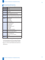
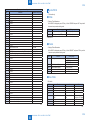
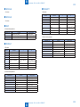
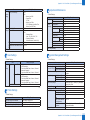
Wireless LAN Specications
Standard IEEE 802.11g, IEEE 802.11b, IEEE 802.11n
Frequency Range 2,412 to 2,462 MHz
Data Transmission Rate
• IEEE 802.11g
6/9/12/18/24/36/48/54 Mbps
• IEEE 802.11b
1/2/5.5/11 Mbps
• IEEE 802.11n
SGI Invalidated 20 MHz: 6.5/13/19.5/26/39/52/58.5/65 Mbps
SGI Validated 20 MHz: 7.2/14.4/21.7/28.9/43.3/57.8/72.2 Mbps
Communication Mode Infrastructure Mode
Security WEP 64/128 bit, WPA-PSK (TKIP/AES), WPA2-PSK (AES),
802.1x (LEAP, EAP-FAST, PEAP, EAP-TLS, EAP-TTLS)
Connection Method WPS (Wi-Fi Protected Setup), Manual setup
*
WPS (Wi-Fi Protected Setup), Connection can be established by manually setting values.
T-1-3
SADF/DADF Specications
Document pickup method Auto pickup method
Document setting direction face-up method
Document type Sheet document
Document size DADF Size: A4R/B5R/A5/B6 (landscape)/LGL/LTRR
2-sided: A4R/B5R/A5/LTRR/LGL/B6 (landscape only)
• Feed direction : 127 mm to 356 mm
• Width direction : 140 mm to 216 mm
SADF Size: A4R/B5R/A5/B6 (landscape)/LGL/LTRR
• Feed direction : 105 mm to 356 mm
• Width direction : 148 mm to 216 mm
Document
processing mode
SADF 1-sided document -> 1-sided copy, 1-sided document -> 2-sided copy
DADF 1-sided document -> 1-sided copy, 1-sided document -> 2-sided copy,
2-sided document -> 1-sided copy, 2-sided document -> 2-sided copy
Document weight Continuous feed 1-sided : 50 to 105 g/m
2
Continuous reading 2-sided : 60 to 105 g/m
2
Document stack
capacity *
DADF S size: 50 Sheets/L size : 10 Sheets
SADF S size: 35 Sheets/L size : 10 Sheets
Document setting position Center reference
Document reading method Stream reading
Mixed paper reading None
Document size sensor None
Document AE sensor None
Stamp function None
Document feed
speed
(at reading)
100 % DADF: 129.34 mm/s
SADF: 113.38 mm/s
Document
processing speed
(At A4, LTR)
Mono
• 1-sided constant speed, DADF
22 ipm (sheets/min)
• 1-sided constant speed, SADF
20 ipm (sheets/min)
• 2-sided constant speed, DADF
8 ipm (sheets/min)
Color
• 1-sided constant speed, DADF
15 ipm (sheets/min)
• 1-sided constant speed, SADF
15 ipm (sheets/min)
• 2-sided constant speed, DADF
5 ipm (sheets/min)
*:
Ssize: A4R, B5R, A5R, B6, LTRR, STMTR, 16KR
L size: LGL
T-1-4

1
1
1-7
1-7
Product Overview > Product Specications > FAX Specications(FAX model Only)
Product Overview > Product Specications > FAX Specications(FAX model Only)
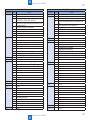
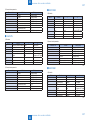
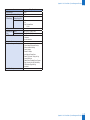
FAX Specications(FAX model Only)
Line Used Public Switched Telephone Network (PSTN)*1
Communication Mode Super G3, G3
Compression Method MH, MR, MMR
Modem Speed Super G3: 33.6 Kbps, G3: 14.4 Kbps
Automatic Fallback
Transmission Speed Approx. 3 seconds per page*2
(ECM-MMR, transmitting from the memory at 33.6 Kbps)
Sending from Memory/
Receiving in Memory
Maximum approx. 256 pages*2 (Total pages of transmission/reception)
(Maximum number of fax jobs that can be sent from the memory: 10 jobs/
Maximum number of fax jobs that can be received into the memory: 90 jobs)
Fax Resolution
• Normal: 200 x 100 dpi
• Fine: 200 x 200 dpi
• Photo: 200 x 200 dpi
• Superne: 200 x 400 dpi
Dialing
• One-touch keys (4 destinations)
• Coded dialing (100 destinations)
• Group dialing (103 groups)
• Address Book dialing
• Regular dialing (with numeric keys)
• Automatic redialing
• Manual redialing
• Sequential broadcast (114 destinations)
Receiving
• Automatic reception
• Remote reception by telephone (Default ID: 25)
Reports
• Send Results
• Transmission management report
(By default, auto output every 40 destinations)
• RX Results
Telephone Type External telephone/External telephone with the built-in answer function/Data
modem
*1 The Public Switched Telephone Network (PSTN) currently supports 28.8 Kbps modem
speed or lower. Note that speeds can vary depending on the telephone line conditions.
*2 Based on ITU-T (ITU Telecommunication Standardization Sector) Standard Chart No. 1,
MMR standard mode.
T-1-5

1
1
1-8
1-8
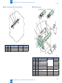
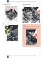
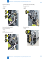
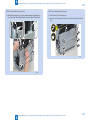
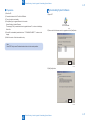
Product Overview > Name of Parts > External View > SADF Unit and Reader Unit
Product Overview > Name of Parts > External View > SADF Unit and Reader Unit
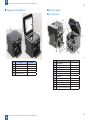
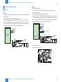
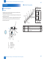
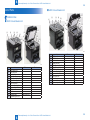
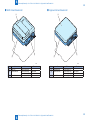
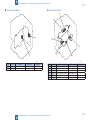
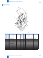
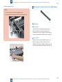
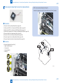
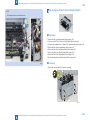
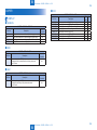
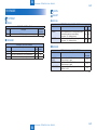
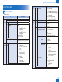
Name of Parts
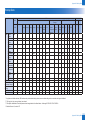
External View
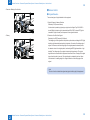
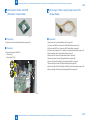
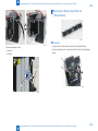
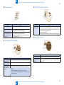
■
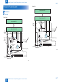
DADF Unit and Reader Unit
[10]
[13]
[12]
[11]
[1]
[2] [3] [4]
[5]
[6]
[7]
[9]
[8]
No. Name Remarks
[1] DADF Upper Cover -
[2] DADF Rear Cover -
[3] Side Guide Plate -
[4] Original Feed Tray -
[5] Original Feed Auxiliary Tray -
[6] Original Delivery Tray -
[7] DADF Front Cover -
[8] Document Reading Glass -
[9] Copyboard Guide Holder -
[10] White Guide Plate -
[11] White Plate -
[12] Copyboard Glass -
[13] Copyboard Upper Cover -
F-1-6
T-1-6
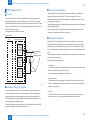
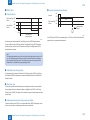
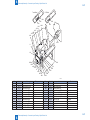
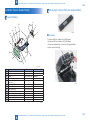
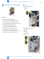
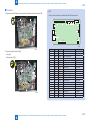
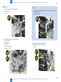
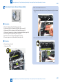
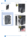
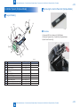
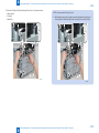
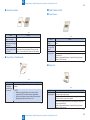
■
SADF Unit and Reader Unit
[10]
[13]
[12]
[11]
[1]
[2] [3] [4]
[5]
[6]
[7]
[8]
[9]
No. Name Remarks
[1] SADF Upper Cover -
[2] SADF Rear Cover -
[3] Side Guide Plate -
[4] Original Feed Tray -
[5] Original Feed Auxiliary Tray -
[6] Original Delivery Tray -
[7] SADF Front Cover -
[8] Document Reading Glass -
[9] Copyboard Guide Holder -
[10] White Guide Plate -
[11] White Plate -
[12] Copyboard Glass -
[13] Copyboard Upper Cover -
F-1-7
T-1-7

1
1
1-9
1-9
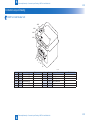
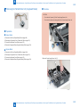
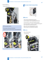
Product Overview > Name of Parts > External View > Printer Unit (Duplex)
Product Overview > Name of Parts > External View > Printer Unit (Duplex)
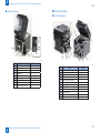
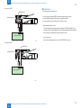
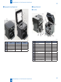
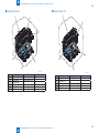
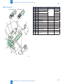
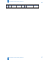
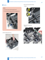
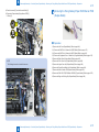
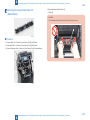
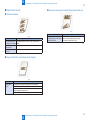
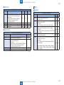
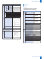
■
Copyboard Unit and Reader Unit
[1]
[4]
[2]
[3]
[5]
No. Name Remarks
[1] Copyboard Upper Cover -
[2] Copyboard Guide Holder -
[3] White Plate -
[4] Copyboard Glass -
[5] Copyboard Upper Cover -
F-1-8
T-1-8
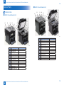
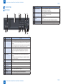
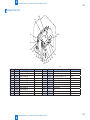
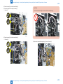
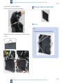
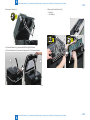
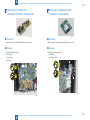
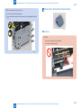
■
Printer Unit (Duplex)
●
Front Side (Duplex)
[10]
[1]
[11]
[2]
[12]
[3]
[4]
[5]
[6]
[7]
[8]
[9]
No. Name Remarks
[1] Control Panel Unit -
[2] Delivery Auxiliary Tray -
[3] Pickup Tray -
[4] Trailing Edge Paper Guides -
[5] Pickup Tray Side Guide Plate -
[6] Power Switch -
[7] Upper Cover -
[8] Delivery Tray -
[9] Front Cover Unit -
[10] Multi-Purpose Tray -
[11] Tray Cover -
[12] Multi-Purpose Tray Side Guide Plate -
F-1-9
T-1-9

1
1
1-10
1-10
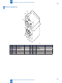
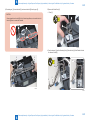
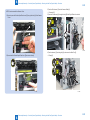
Product Overview > Name of Parts > External View > Printer Unit (Sinplex)
Product Overview > Name of Parts > External View > Printer Unit (Sinplex)
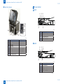
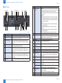
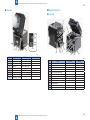
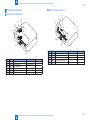
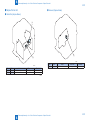
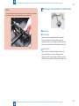
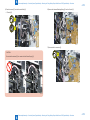
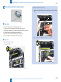
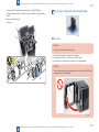
●
Rear Side (Duplex)
[13]
[14]
[15]
[16]
[17]
[18]
[19]
[20]
[21]
No. Name Remarks
[13] Left Cover -
[14] Hinge Face Cover -
[15] Duplex Feed Guide Unit -
[16] Right Cover -
[17] USB Device Port -
[18] LAN Port Model with NET
[19] External Device Jack Model with FAX
[20] Telephon Line Jack Model with FAX
[21] Power Supply Cord Slot -
F-1-10
T-1-10
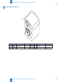
■
Printer Unit (Sinplex)
●
Front Side (Sinplex)
[10]
[1]
[11]
[2]
[12]
[3]
[4]
[5]
[6]
[7]
[8]
[9]
No. Name Remarks
[1] Control Panel Unit -
[2] Delivery Auxiliary Tray -
[3] Pickup Tray -
[4] Trailing Edge Paper Guides -
[5] Pickup Tray Side Guide Plate -
[6] Power Switch -
[7] Upper Cover -
[8] Delivery Tray -
[9] Front Cover Unit -
[10] Multi-Purpose Tray -
[11] Tray Cover -
[12] Multi-Purpose Tray Side Guide Plate -
F-1-11
T-1-11
Page is loading ...
Page is loading ...
Page is loading ...
Page is loading ...
Page is loading ...
Page is loading ...
Page is loading ...
Page is loading ...
Page is loading ...
Page is loading ...
Page is loading ...
Page is loading ...
Page is loading ...
Page is loading ...
Page is loading ...
Page is loading ...
Page is loading ...
Page is loading ...
Page is loading ...
Page is loading ...
Page is loading ...
Page is loading ...
Page is loading ...
Page is loading ...
Page is loading ...
Page is loading ...
Page is loading ...
Page is loading ...
Page is loading ...
Page is loading ...
Page is loading ...
Page is loading ...
Page is loading ...
Page is loading ...
Page is loading ...
Page is loading ...
Page is loading ...
Page is loading ...
Page is loading ...
Page is loading ...
Page is loading ...
Page is loading ...
Page is loading ...
Page is loading ...
Page is loading ...
Page is loading ...
Page is loading ...
Page is loading ...
Page is loading ...
Page is loading ...
Page is loading ...
Page is loading ...
Page is loading ...
Page is loading ...
Page is loading ...
Page is loading ...
Page is loading ...
Page is loading ...
Page is loading ...
Page is loading ...
Page is loading ...
Page is loading ...
Page is loading ...
Page is loading ...
Page is loading ...
Page is loading ...
Page is loading ...
Page is loading ...
Page is loading ...
Page is loading ...
Page is loading ...
Page is loading ...
Page is loading ...
Page is loading ...
Page is loading ...
Page is loading ...
Page is loading ...
Page is loading ...
Page is loading ...
Page is loading ...
Page is loading ...
Page is loading ...
Page is loading ...
Page is loading ...
Page is loading ...
Page is loading ...
Page is loading ...
Page is loading ...
Page is loading ...
Page is loading ...
Page is loading ...
Page is loading ...
Page is loading ...
Page is loading ...
Page is loading ...
Page is loading ...
Page is loading ...
Page is loading ...
Page is loading ...
Page is loading ...
Page is loading ...
Page is loading ...
Page is loading ...
Page is loading ...
Page is loading ...
Page is loading ...
Page is loading ...
Page is loading ...
Page is loading ...
Page is loading ...
Page is loading ...
Page is loading ...
Page is loading ...
Page is loading ...
Page is loading ...
Page is loading ...
Page is loading ...
Page is loading ...
Page is loading ...
Page is loading ...
Page is loading ...
Page is loading ...
Page is loading ...
Page is loading ...
Page is loading ...
Page is loading ...
Page is loading ...
Page is loading ...
Page is loading ...
Page is loading ...
Page is loading ...
Page is loading ...
Page is loading ...
Page is loading ...
Page is loading ...
Page is loading ...
Page is loading ...
Page is loading ...
Page is loading ...
Page is loading ...
Page is loading ...
Page is loading ...
Page is loading ...
Page is loading ...
Page is loading ...
Page is loading ...
Page is loading ...
Page is loading ...
Page is loading ...
Page is loading ...
Page is loading ...
Page is loading ...
Page is loading ...
Page is loading ...
Page is loading ...
Page is loading ...
Page is loading ...
Page is loading ...
Page is loading ...
Page is loading ...
Page is loading ...
Page is loading ...
Page is loading ...
Page is loading ...
Page is loading ...
Page is loading ...
Page is loading ...
Page is loading ...
Page is loading ...
Page is loading ...
Page is loading ...
Page is loading ...
Page is loading ...
Page is loading ...
Page is loading ...
Page is loading ...
Page is loading ...
Page is loading ...
Page is loading ...
Page is loading ...
Page is loading ...
Page is loading ...
Page is loading ...
Page is loading ...
Page is loading ...
Page is loading ...
Page is loading ...
Page is loading ...
Page is loading ...
Page is loading ...
Page is loading ...
Page is loading ...
Page is loading ...
Page is loading ...
Page is loading ...
Page is loading ...
Page is loading ...
Page is loading ...
Page is loading ...
Page is loading ...
Page is loading ...
Page is loading ...
Page is loading ...
Page is loading ...
Page is loading ...
Page is loading ...
Page is loading ...
Page is loading ...
Page is loading ...
Page is loading ...
Page is loading ...
Page is loading ...
Page is loading ...
Page is loading ...
Page is loading ...
Page is loading ...
Page is loading ...
Page is loading ...
Page is loading ...
Page is loading ...
Page is loading ...
Page is loading ...
Page is loading ...
Page is loading ...
Page is loading ...
Page is loading ...
Page is loading ...
Page is loading ...
Page is loading ...
Page is loading ...
Page is loading ...
Page is loading ...
Page is loading ...
Page is loading ...
Page is loading ...
Page is loading ...
Page is loading ...
Page is loading ...
Page is loading ...
Page is loading ...
Page is loading ...
Page is loading ...
Page is loading ...
Page is loading ...
Page is loading ...
Page is loading ...
Page is loading ...
Page is loading ...
Page is loading ...
Page is loading ...
Page is loading ...
Page is loading ...
Page is loading ...
Page is loading ...
Page is loading ...
Page is loading ...
Page is loading ...
Page is loading ...
Page is loading ...
Page is loading ...
Page is loading ...
Page is loading ...
Page is loading ...
Page is loading ...
Page is loading ...
Page is loading ...
Page is loading ...
Page is loading ...
Page is loading ...
Page is loading ...
Page is loading ...
Page is loading ...
Page is loading ...
Page is loading ...
Page is loading ...
Page is loading ...
Page is loading ...
Page is loading ...
Page is loading ...
Page is loading ...
Page is loading ...
Page is loading ...
Page is loading ...
Page is loading ...
Page is loading ...
Page is loading ...
Page is loading ...
Page is loading ...
-
 1
1
-
 2
2
-
 3
3
-
 4
4
-
 5
5
-
 6
6
-
 7
7
-
 8
8
-
 9
9
-
 10
10
-
 11
11
-
 12
12
-
 13
13
-
 14
14
-
 15
15
-
 16
16
-
 17
17
-
 18
18
-
 19
19
-
 20
20
-
 21
21
-
 22
22
-
 23
23
-
 24
24
-
 25
25
-
 26
26
-
 27
27
-
 28
28
-
 29
29
-
 30
30
-
 31
31
-
 32
32
-
 33
33
-
 34
34
-
 35
35
-
 36
36
-
 37
37
-
 38
38
-
 39
39
-
 40
40
-
 41
41
-
 42
42
-
 43
43
-
 44
44
-
 45
45
-
 46
46
-
 47
47
-
 48
48
-
 49
49
-
 50
50
-
 51
51
-
 52
52
-
 53
53
-
 54
54
-
 55
55
-
 56
56
-
 57
57
-
 58
58
-
 59
59
-
 60
60
-
 61
61
-
 62
62
-
 63
63
-
 64
64
-
 65
65
-
 66
66
-
 67
67
-
 68
68
-
 69
69
-
 70
70
-
 71
71
-
 72
72
-
 73
73
-
 74
74
-
 75
75
-
 76
76
-
 77
77
-
 78
78
-
 79
79
-
 80
80
-
 81
81
-
 82
82
-
 83
83
-
 84
84
-
 85
85
-
 86
86
-
 87
87
-
 88
88
-
 89
89
-
 90
90
-
 91
91
-
 92
92
-
 93
93
-
 94
94
-
 95
95
-
 96
96
-
 97
97
-
 98
98
-
 99
99
-
 100
100
-
 101
101
-
 102
102
-
 103
103
-
 104
104
-
 105
105
-
 106
106
-
 107
107
-
 108
108
-
 109
109
-
 110
110
-
 111
111
-
 112
112
-
 113
113
-
 114
114
-
 115
115
-
 116
116
-
 117
117
-
 118
118
-
 119
119
-
 120
120
-
 121
121
-
 122
122
-
 123
123
-
 124
124
-
 125
125
-
 126
126
-
 127
127
-
 128
128
-
 129
129
-
 130
130
-
 131
131
-
 132
132
-
 133
133
-
 134
134
-
 135
135
-
 136
136
-
 137
137
-
 138
138
-
 139
139
-
 140
140
-
 141
141
-
 142
142
-
 143
143
-
 144
144
-
 145
145
-
 146
146
-
 147
147
-
 148
148
-
 149
149
-
 150
150
-
 151
151
-
 152
152
-
 153
153
-
 154
154
-
 155
155
-
 156
156
-
 157
157
-
 158
158
-
 159
159
-
 160
160
-
 161
161
-
 162
162
-
 163
163
-
 164
164
-
 165
165
-
 166
166
-
 167
167
-
 168
168
-
 169
169
-
 170
170
-
 171
171
-
 172
172
-
 173
173
-
 174
174
-
 175
175
-
 176
176
-
 177
177
-
 178
178
-
 179
179
-
 180
180
-
 181
181
-
 182
182
-
 183
183
-
 184
184
-
 185
185
-
 186
186
-
 187
187
-
 188
188
-
 189
189
-
 190
190
-
 191
191
-
 192
192
-
 193
193
-
 194
194
-
 195
195
-
 196
196
-
 197
197
-
 198
198
-
 199
199
-
 200
200
-
 201
201
-
 202
202
-
 203
203
-
 204
204
-
 205
205
-
 206
206
-
 207
207
-
 208
208
-
 209
209
-
 210
210
-
 211
211
-
 212
212
-
 213
213
-
 214
214
-
 215
215
-
 216
216
-
 217
217
-
 218
218
-
 219
219
-
 220
220
-
 221
221
-
 222
222
-
 223
223
-
 224
224
-
 225
225
-
 226
226
-
 227
227
-
 228
228
-
 229
229
-
 230
230
-
 231
231
-
 232
232
-
 233
233
-
 234
234
-
 235
235
-
 236
236
-
 237
237
-
 238
238
-
 239
239
-
 240
240
-
 241
241
-
 242
242
-
 243
243
-
 244
244
-
 245
245
-
 246
246
-
 247
247
-
 248
248
-
 249
249
-
 250
250
-
 251
251
-
 252
252
-
 253
253
-
 254
254
-
 255
255
-
 256
256
-
 257
257
-
 258
258
-
 259
259
-
 260
260
-
 261
261
-
 262
262
-
 263
263
-
 264
264
-
 265
265
-
 266
266
-
 267
267
-
 268
268
-
 269
269
-
 270
270
-
 271
271
-
 272
272
-
 273
273
-
 274
274
-
 275
275
-
 276
276
-
 277
277
-
 278
278
-
 279
279
-
 280
280
-
 281
281
-
 282
282
-
 283
283
-
 284
284
-
 285
285
-
 286
286
-
 287
287
-
 288
288
-
 289
289
-
 290
290
-
 291
291
-
 292
292
-
 293
293
-
 294
294
-
 295
295
-
 296
296
-
 297
297
-
 298
298
-
 299
299
-
 300
300
-
 301
301
-
 302
302
-
 303
303
-
 304
304
-
 305
305
-
 306
306
-
 307
307
-
 308
308


Canon i-SENSYS MF212w User manual
- Category
- Fax machines
- Type
- User manual
- This manual is also suitable for
Ask a question and I''ll find the answer in the document
Finding information in a document is now easier with AI
Related papers
-
Canon 3235 Series User manual
-
Canon iR5570 Series User manual
-
-
-
-
-
-
-
-
Canon Unit-AE1 User manual