Page is loading ...

1
Copyboard
M-
5
User’s Manual
(
CD-ROM Edition
)
Thank you for your purchase of the PLUS Copyboard.
Please read this User’s Manual (CD-ROM Edition) carefully before use
to take full advantage of the functions of this product. After you have
finished reading the manual, please keep it for future reference.

2
Trademarks
• Microsoft and Windows are registered trademarks or trademarks in the United States and other countries of the Microsoft
Corporation.
• IBM and PC/AT are registered trademarks of International Business Machines Corporation of the United States.
• Adobe and Adobe Acrobat Reader are trademarks of Adobe Systems Incorporated.
• CompactFlash and CF are trademarks of SanDisk.
The trademarks of the various companies and the product trademarks, even when not written down, will be given due respect.
Product names and company names appearing in this manual are registered trademarks or trademarks of the respective companies.
(1) The contents of this manual may not be reprinted in part or whole without permission.
(2) The contents of this manual are subject to change without notice.
(3) Great care has been taken in the creation of this manual; however, should any questionable points, errors, or omissions be
apparent, please contact us.
(4) Notwithstanding Section (3), this company will not be responsible for any claims of loss or profit or other matters deemed to be
the result of using this unit.
(5) Manuals with incorrect collating or missing pages will be replaced.

3
Table of Contents
IMPORTANT SAFETY INFORMATION ------------------------------------------------------------ 4
Packaged Contents ------------------------------------------------------------------------------------ 6
Names of Parts ------------------------------------------------------------------------------------------ 7
Installation and Assembly Instructions -------------------------------------- 8
Read This Before Installing -------------------------------------------------------------------------------------- 9
Cautions on Installation --------------------------------------------------------------------------------------------------------9
Types of Installation -------------------------------------------------------------------------------------------------------------9
Installing on a Wall ------------------------------------------------------------------------------------------------ 10
Installing on a Stand --------------------------------------------------------------------------------------------- 13
Assembling the stand and mounting the copyboard horizontally -------------------------------------------------- 13
Assembling the stand and mounting the copyboard vertically ----------------------------------------------------- 15
Installing on a Partition-Panel -------------------------------------------------------------------------------- 17
Assembly and installation ---------------------------------------------------------------------------------------------------- 17
Operation Instructions ---------------------------------------------------------- 19
Usage Guide -------------------------------------------------------------------------------------------------------------------- 19
Names of Main Unit Controls and Connectors ---------------------------------------------------------- 20
Handling CF Memory Cards ------------------------------------------------------------------------------------------------ 21
Scanning area ------------------------------------------------------------------------------------------------------------------ 21
Operating the Copyboard -------------------------------------------------------------------------------------- 22
Connecting the AC power adapter and turning the power on and off -------------------------------------------- 22
Saving the Image on the Sheet -------------------------------------------------------------------------------------------- 23
Saving sheet images in the built-in memory ----------------------------------------------------------------------- 23
Saving sheet images on a CF memory card ---------------------------------------------------------------------- 24
Clearing the built-in Memory ------------------------------------------------------------------------------------------------ 25
Scrolling the Sheet ------------------------------------------------------------------------------------------------------------ 25
Ver tical/Horizontal Position Setting ---------------------------------------------------------------------------------------- 25
Storing Image Files on a Computer ------------------------------------------------------------------------- 26
Storing/Deleting Directly with USB Connections (from built-in memory or CF memory card) -------------- 26
Using a PC Card Adapter or Memory Card Reader/Writer (USB type) ------------------------------------------ 30
Using a PC card adapter ----------------------------------------------------------------------------------------------- 30
Using a memory card reader/writer (USB type) ------------------------------------------------------------------ 31
Troubleshooting --------------------------------------------------------------------------------------------------- 32
Specifications ------------------------------------------------------------------------------------------------------ 33
Quick Calibration -------------------------------------------------------------------------------------------------- 34
Software Guide --------------------------------------------------------------------- 35
Before Using the Software ------------------------------------------------------------------------------------- 36
Software Contents and Overview ------------------------------------------------------------------------------------------ 36
Operating Environment ------------------------------------------------------------------------------------------------------- 36
Windows 98SE Personal Computer and USB Connections ---------------------------------------- 37
Driver Setup (Windows 98SE) ---------------------------------------------------------------------------------------------- 37
Uninstalling the Driver (Windows 98SE) --------------------------------------------------------------------------------- 38
Windows Me / 2000/ XP Personal Computer and USB Connections ----------------------------- 39
Disconnecting of the Copyboard ---------------------------------------------------------------------------- 40
Windows 98SE ----------------------------------------------------------------------------------------------------------------- 40
Windows Me / 2000 / XP ----------------------------------------------------------------------------------------------------- 40
M-5 Setup Utility --------------------------------------------------------------------------------------------------- 41
Installation ----------------------------------------------------------------------------------------------------------------------- 41
Starting up ----------------------------------------------------------------------------------------------------------------------- 41
Electronic User’s Manual --------------------------------------------------------------------------------------- 42
Acrobat Reader Installation ------------------------------------------------------------------------------------------------- 42
Opening the M-5 User’s Manual ------------------------------------------------------------------------------------------- 42
PLUS Image Viewer ----------------------------------------------------------------------------------------------- 43
Installation ----------------------------------------------------------------------------------------------------------------------- 43
Starting up ----------------------------------------------------------------------------------------------------------------------- 43
Deleting the Software -------------------------------------------------------------------------------------------- 44

4
IMPORTANT SAFETY INFORMATION
WARNING
The unit’s rear panel should never be opened by anyone other than a qualified serviceperson. There are
many high voltage parts inside the unit, and touching them is dangerous. For replacement of the light
source, internal inspections, adjustments, repairs or internal cleaning, please contact your store of pur-
chase.
CAUTION
Continued use of the unit under abnormal conditions (when the unit is emitting smoke, unusual odors or
sounds) could lead to fire or electric shocks.
Turn off the unit’s power immediately, then unplug the AC power adapter from the power outlet.
Check that no more smoke, etc., is being emitted, then contact a sales outlet for repairs.
Repairing the unit yourself is dangerous. Never attempt to do so.
WARNING
This is a FCC class A product. In a home environment this product may cause radio interference in which case the
user may be required to take adequate measures.
This symbol warns the user that uninsulated voltage within the unit may have sufficient magnitude to cause electric shock.
Therefore, it is dangerous to make any kind of contact with any part inside of this unit.
This symbol alerts the user that important literature concerning the operation and maintenance of this unit has been
included. Therefore, it should be read carefully in order to avoid any problems.
SAFETY PRECAUTIONS
Heeding the safety precautions below will lengthen the product’s service life and prevent fires, electric shocks and injury. Read these
safety precautions carefully and be sure to heed them.
Handling the AC power adapter
• Do not connect any AC adapter other than the dedicated one to the unit. Doing so could result in fire or other accidents.
• Do not use with voltages other than the voltage indicated. Doing so could result in fire or electric shock.
• Do not let the AC power adapter get wet. Doing so could result in fire or electric shock.
• Do not subject the AC power adapter to shocks. Doing so could result in fire or electric shock.
Handling the AC power adapter’s cord and plug
• Damaging the power cord could lead to fire or electric shock.
* When installing, do not squeeze the power cord between the product and a wall, rack, etc.
* Do not modify or damage the power cord.
* Do not place heavy objects on the power cord or pull strongly on it.
* Do not place the power cord near heating appliances or otherwise heat it.
* When unplugging the power cord, always do so by pulling on the plug, not the cord.
If the power cord should be damaged, ask your store of purchase to replace it.
• If there is dust or metal objects on or near the power plug’s blades, unplug the power cord then wipe the blade area clean using a
dry cloth. Continued use without cleaning the plug could lead to fire or electric shock.
• Do not plug in or unplug the power cord with wet hands. Doing so could lead to electric shock.
• When moving the unit, turn off the power and be sure to unplug the power cord from the AC outlet first. Moving the unit with the
power cord plugged in could damage the cord, leading to fire or electric shock.
• Connect the power plug securely to the AC outlet, pressing the blades in to the hilt. Uncomplete plugging could cause heating or
attract dust, leading to fire. In addition, touching the plug’s blades could cause electric shock.

5
Installation
• When the copyboard is mounted on a stand, be sure to lock the casters.
• When mounting on a wall, be sure to check first that the wall surface is strong enough to support the total weight of the main unit
and mount fittings over a long period of time (including during earthquakes). If the wall is not strong enough, reinforce it before
mounting the unit.
• Getting water on or inside the unit etc., could lead to fire or electric shock. Be particularly careful when using the unit near a window
when it is raining or snowing and when using it near the shore of the ocean and lakes.
• Do not set the unit in hot places exposed to direct sunlight or in places exposed to wind coming directly from an air conditioner.
Do not set the unit in places exposed to soot or humidity (on kitchen counters, near humidifiers, etc.).
Preventing Tipping (when mounted on a stand)
To prevent tipping, heed the instructions below. Tipping could lead to personal injury or damage the unit.
• Place the unit on a flat floor.
• Lock the casters when using the unit. When moving it, be sure to unlock the casters to prevent tipping.
• Do not lean against the unit or apply excess force to the top of the unit.
Care and Cleaning
Cautions on Usage
•Take care that the unit does not get wet and that water does not get inside. Do not place objects containing chemicals, water or
other liquids (vases, potted plants, glasses, cosmetics, etc.) on top of the unit. The liquid could spill and get inside the unit, leading
to fire or electric shock.
• When lifting the unit to hang it on the stand, etc., the unit should be lifted by at least two persons to prevent it from tipping and
causing personal injury.
• Do not move the sheet with paper or other objects attached to it. Doing so could cause damage.
• Do not wipe the unit or sheet with thinner, benzene, alcohol or other such products. Doing so could cause discoloration or damage
the sheet.
• Only use markers designed exclusively for this product.
Using other markers could damage the sheet. Also note that it may not be possible to erase the ink of other markers.
• When moving the unit mounting on the stand, be sure to unlock the casters, then support the unit from both sides and move it
gently and carefully to avoid shocks.
• When not using for long periods of time, for safety be sure to unplug the AC power adapter from the power outlet.
Handling the CD-ROM
• Do not touch the surface on which nothing is printed (the surface on which the data is recorded). If this surface is dirty the data will
not be read properly.
Also, do not stick paper, stickers, etc., on the CD-ROM.
• Do not leave for long periods of time in places exposed to direct sunlight or near heating appliances, and do not drop or bend the
CD-ROM. The disc may get warped, making it impossible to read the data.
Cleaning
• If the sheet is dirty, wipe it clean using a damp, thoroughly wrung out cloth. For tough dirt, apply some diluted neutral detergent to
a cloth, wipe off the dirt, then wipe again to remove any detergent.
Wait until the sheet is completely dry before using it.
• Do not wipe the copyboard or sheet with thinner, benzene, alcohol, etc. Doing so could cause discoloration or damage the sheet.
• Use a damp, thoroughly wrung out cloth to wipe any dust of markers on the marker tray or the frame.
Do not use the included CD-ROM in a player designed for audio CDs.
•Never use the included CD-ROM in a player designed for audio CDs. Doing so could produce loud noises that could impair your
hearing. These noises can also damage your speakers.

6
Packaged Contents
The contents included in the package are described below. Make sure that all items are included before starting.
Copyboard (main unit) … 1
Accessories included with copyboard
• Set of markers … 2 (black and red)
Use these special markers to draw or write on the sheet.
•Eraser … 1
Use this to erase what you have drawn or written.
•AC power adapter (with 3 meter power cord) … 1
This is the power adapter for supplying power to the
copyboard.
• USB cable (type B 씯씮 type A, 3 meters) … 1
Use this cable to connect the copyboard with a computer.
• Phillips screwdriver ... 1
Use this when setting up the
Copyboard.
• Cosmetic seals ...1 sheet for 11 pieces
To cover screw holes and screws, peel a cosmetic seal from
the backing sheet and apply it.
• Marker tray (1 set)
Put the markers and the eraser on this tray (when the
copyboard is installed horizontally).
(Includes 2 side covers and 3 M4 x 8 screws)
(screws removed from the
Copyboard when unpacking)
•Wall mount fittings (1 set)
Use these fittings to mount the copyboard to a wall.
(1 wall mount bar, 2 upper brackets, 2 lower brackets, 8 M4
⳯ 12 bracket mounting screws)
Documents
Operating instructions (simplified version) … 1
Wall mount positioning sheet … 1
CD-ROM … 1
(including operating instructions (in PDF
format), Windows 98SE driver and PLUS Image Viewer)
Upper brackets
Lower brackets

7
Names of Parts
Front and top
Back and bottom
This diagram shows the copyboard set with the front
side facing down.
1. Copyboard
2. Sheet
3. Control panel (see page 20)
4. DC input jack (see page 20)
5. USB connector (type B) (see page 20)
6. Screw holes for mounting the marker tray
7. Screw holes for mounting the wall mount fittings
(for upper brackets)
8. Screw holes for mounting the wall mount fittings
(for brackets)
9. Screw holes for installing the stand horizontaly
(for upper brackets)
10. Screw holes for installing the stand horizontaly
(for lower brackets)
11. Screw holes for installing the stand vertically
(for upper brackets)
12. Screw holes for installing the stand vertically
(for lower brackets)
12
1
2
3
7, 9
8, 10
6
5
4
12
11
11

8
Installation and
Assembly
Instructions
To the Customer
Specialized techniques are required in the wall mounting of the
Copyboard. Please do not attempt any installation work unless
you have the techniques.
To the Dealer or Installation Tradesman
In the interest of the safety of the customer, please perform instal-
lation work paying due attention to the strength of the installation
location to ensure that it can bear the load of the Copyboard and
installation parts.

9
Read This Before Installing
WARNINGS
• Be sure to install and assemble the copyboard as instructed in this manual. Improper installation or assembly
could lead to injury.
• At least two people should hold the copyboard when installing and removing it.
•To prevent the copyboard from falling off the wall, install the copyboard on a sufficiently strong surface and in
such a way that the weight of both the copyboard and the mounting hardware can be supported for an extended
period of time, even in earthquakes. Improper installation could lead to the copyboard falling and causing injury.
• Use M6 screws or the equivalent to fix the copyboard to the wall. If any other screws are used, the copyboard
could fall, causing injury.
• Install on a wall surface reinforced by sturdy studs.
• When installing on a concrete wall, use anchor nuts and anchor bolts.
Types of Installation
On a wall (horizontal or vertical)
Horizontal Position:
Use the wall mount fittings included with the copyboard to mount the
unit directly on the wall. The copyboard can be installed in the horizon-
tal direction.
Vertical Position:
Use of the vertical wall mounting kit allows the Copyboard to be in-
stalled in the vertical orientation. (Vertical wall mounting kit: Model M-
5- W, order code 44-563)
On a stand (horizontal or vertical)
Mount the copyboard on an optional stand for mobility. The copyboard
can be mounted in either the horizontal or vertical position. (Stand Kit
: Model M-5-T, order code: 44-562)
On a partition-Panel
Use an optional partition mount kit to hang the copyboard onto a par-
tition panel. (Partition hanger Kit : Model M-5-P, order code: 44-552)
Cautions on Installation

10
Installing on a Wall
Parts included in the copyboard package:
Wall mount bar (1 pc), upper brackets (2 pcs),
Marker tray (1 pc, with 2 side covers) and M4 x 8 marker tray installation screws (3 pcs, screws removed
when unpacking), lower brackets (2 pcs), M4 x 12 bracket mounting screws (8 pcs)
Parts not included in the copyboard package:
Bolts and nuts for fastening to wall (use commercially available parts – the types differ according to wall
surface material). See page 11.
Mounting
the copyboard
onto the wall
Selecting the place
of installation
Preparing
the wall surface
Mounting the wall
mount bar
Mounting
the marker tray
on the copyboard
Mounting
the brackets
on the copyboard
Wall mounting procedure – flow
(1) Selecting the place of installation
• The wall mount bar should be mounted on columns,
posts, or wall which is strong enough to support the
weight of the copyboard.
• The diagram shows the wall mount bar’s position of
installation. The wall mount bar has 8 mm diameter
screw holes at 100 mm intervals.
• Choose holes in such a way that the center of gravity
will be at the middle. (Make sure there is no extreme
imbalance.)
• The included “wall mount positioning sheet” can be
used to easily mark the position of installation.
For concrete walls
Mount commercially available M6 anchor bolts and
anchor nuts to the position of installation. (See the
following page.)
655
300 (275 330)
800
100
100
100
100
100
100
100
100
663
Position of upper
bracket (hook)
Position of lower
bracket
Wall mount bar mounting
position
655
800
100
100
100
100
100
100
100
100
663
Wooden or thick
plywood wall
Position of lower
bracket
Position of upper
bracket (hook)
Wall mount bar mounting position
Column, stud, etc.
For walls with a plywood or plaster board struc-
ture
Check that there are columns or studs at the position
of installation.
Install using the wall mount bar’s M6 wood screws,
etc. (See the following page.)
Mount the lower brackets in the position on the dia-
gram shown for the wood screws for when installing
the copyboard.
Notice:
•For structures with no columns, use a separately sold
stand.
An optional partition mount kit is also available for mount-
ing the copyboard on a partition panel.

11
1 2
1 2 3
[Reference] Method of installation for different wall materials
Select the type of installation best suited for the wall material.
If the wall is not strong enough, mount the copyboard to columns or studs.
Material of wall Method of installation
Wood Wood screws:
햲Open holes using a drill, then 햳 mount the copyboard
using wood screws.
Concrete U-plugs:
햲 Open the base hole in the wall using a drill, 햳 insert the U-plug, then 햴 fasten the wall
mount bar using screws.
Steel Cross recessed tapping screw (pan head):
Check that there is reinforcement inside the steel wall, open holes with
a drill of the proper diameter, then mount the wall mount bar using tapping
screws.
1
2
3
3
(2) Fix the wall mount bar to the wall surface and
posts.
• Fasten the screws in a minimum of 3 places.
M6 wood screw
Mounting on the wall surface
M6 screw
Mounting on a post
Marker tray
Side covers
M4 x 8 screws
(3) Attach the marker tray to the Copyboard.
햲 Insert the side covers into both ends of the marker
tray.
• Note that there are left and right type side covers.
햳 Temporarily fasten the three M4 x 8 screws into the
Copyboard (leaving about 3 mm)
• Use the supplied screwdriver.
햴 Insert the marker tray over the 3 screws that have
been temporarily fastened, and then tighten securely.
• Please insert the marker tray as far as they will go.

12
(4) Mount the 2 upper and 2 lower brackets included
with the copyboard using M4 x 12 screws.
• Both of the left and right upper brackets are installed in
the same orientation.
M4⳯12 screws Lower bracket
M4⳯12 screws Upper bracket
M4⳯12 screws Upper bracket
Wall mount bar
Upper bracket
Wood screw or anchor
bolt
(M6 or the equivalent)
Lower brackets
(5) Hang the copyboard to the wall mount bar and
fasten the lower brackets.
햲 Catch the left and right upper brackets mounted on
the copyboard onto the wall mount bar.
햳 Fix the left and right lower brackets to the wall surface.
(The way in which the brackets are fixed to the wall
depends on the type of installation to the wall.)
CAUTION
• The upper brackets are not fastened. Do not let the
copyboard slide too much when fixing the lower brack-
ets. Doing so may cause the copyboard to come off the
wall mount bar and fall, resulting in injury.
• At least two people should hold the copyboard to pre-
vent it from dropping or tipping over, resulting in unex-
pected injury.

13
Installing on a Stand
The optional stand kit for both vertical and horizontal installation (Model M-5-T, order code 44-562) is required to
install the copyboard on a stand.
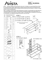
Assembling the stand and mounting the copyboard horizontally
Parts included in the copyboard package: Marker tray (1 pc), side covers (2 pcs), M4 x 8 marker tray installation
screws (3 pcs, screws removed when unpacking), 8 copyboard mount screws (M4 x 12)
List of parts included in the stand kit (parts used for horizontal installation)
Feet (with casters) : 2, Frames : 2, Foot washers : 2, Foot fixing screws (M8 x 50) : 4, Spring washers : 4,
Extension frames : 2, Caps : 6, Fixing knobs (with hexagon cap nuts) : 2, Crossbars : 2,
Hexagonal socket head screws : 4, Flat washers : 4, Upper brackets (left and right) : 2, Lower brackets : 2,
Hexagonal wrench (M8) : 1, Hexagonal wrench (M5) : 1
Assembly and installation flow
Mounting the
copyboard
onto the stand
Assembling
the stand
Mounting
the marker tray
on the copyboard
Mounting
the brackets
on the copyboard
1
2
3
3
3
Cap
Extension frame
Frame
Cap
Cap
Foot
Spring
washer
Foot washer
M8 hexagonal wrench
M8 x 50 hexagonal
socket head screw
T-shaped leg
Crossbar
Crossbar
Flat washer
M5 hexagonal
socket head
screw
M5 hexagonal
wrench
(1) Assemble the T-shaped legs (two).
햲 Mount the foot using washers, spring wash-
ers and M8 x 50 hexagonal socket head
screws.
햳 Make sure of the orientation of the extension frame
and the frame end looking at the marks, then insert
all the way. (Note that it will no longer be possible to
remove the extension frame when the mark sur-
face has been inserted in the opposite orientation.)
Notice:
• Mounting the extension frame makes for a height
of 1700 mm off the floor (compared to 1465 mm
without the extension frame). Use this to adjust
the height.
•For the assembly procedure when not mounting
the extension frames, see step (1) under “Assem-
bling the stand and mounting the copyboard ver-
tically”.
햴 Fit the caps on the top of the frame and feet.
(2) Mount the two crossbars onto the T-shaped
legs assembled in (1) above.
Mount them using the M5 hexagonal socket head
screws and flat washers.
Temporarily fasten the screws using the included M5
hexagonal wrench, then fasten them securely once
both the upper and lower crossbars have been
mounted.
* Assemble in a flat place.

14
3
1
2
3
M4⳯12 screws
Lower bracket
Upper bracket (Left)
Upper bracket (Rightt)
M4⳯12 screws
M4⳯12 screws
Fixing knobs
Hexagon cap nuts
(4) Mount the upper and lower brackets using M4
x 12 screws.
• The left and right upper brackets are differ-
ent. Be sure to mount them on the proper
side.
• Both the lower brackets have the same
form, but mount them in the opposite di-
rections so that each is facing outwards.
(5) Hook the left and right upper brackets of the
Copyboard onto the upper crossbar and fas-
ten the lower brackets using the fixing knobs
and hexagon cap nuts.
CAUTION
• Lock the casters so that the stand does not move.
• When mounting and adjusting the height, at least
two people should hold the copyboard to prevent it
from dropping or tipping over, resulting in unex-
pected injury.
Marker tray
Side covers
(3) Attach the marker tray to the Copyboard.
햲 Insert the side covers into both ends of the marker
tray.
• Note that there are left and right type side covers.
햳 Temporarily fasten the three M4 x 8 screws into the
Copyboard (leaving about 3 mm)
• Use the supplied screwdriver.
햴 Insert the marker tray over the 3 screws that have
been temporarily fastened, and then tighten securely.
• Please insert the marker tray as far as they will
go.
M4 x 8 screws

15
Changing the
image storing
setting to “vertical”
Assembling
the stand
Mounting
the brackets
on the copyboard
Mounting
the copyboard
onto the stand
Mounting the
vertical marker tray
on the copyboard
Assembling the stand and mounting the copyboard vertically
Parts included in the copyboard package: 6 copyboard mount screws (M4 x 12)
List of parts included in the stand kit (parts used for vertical installation)
Feet (with casters) : 2, Frames : 2, Foot washers : 2, Foot fixing screws (M8 x 50) : 4,
Spring washers : 4, Caps : 6, Fixing knobs (with hexagon cap nuts) : 2, Crossbars : 2,
Hexagonal socket head screws : 4, Flat washers : 4, Upper brackets (left and right) : 2, Lower brackets : 2,
Hexagonal wrench (M8) : 1, Hexagonal wrench (M5) : 1, Short marker tray:1, Side covers: 2
M3 decorative screws : 2
Assembly and installation flow
(1) Assemble the T-shaped legs (two).
햲 Mount the foot using two M8 x 50 screws (+ spring
washers).
햳 Fit the caps on the top of the frame and feet.
(2) Mount the two crossbars onto the T-shaped legs
assembled in (1) above.
Mount them using the hexagonal socket head
screws and flat washers.
Temporarily fasten the screws using the included
hexagonal wrench, then fasten them securely once
both the upper and lower crossbars have been
mounted.
* Assemble in a flat place.
1
2
2
2
Cap
Frame
Cap
Cap
Spring
washer
Foot washer
M8 hexagonal wrench
M8 x 50 hexagonal
socket head screw
Foot
T-shaped leg
Crossbar
Crossbar
Flat washer
M5 hexagonal
socket head
screw
M5 hexagonal
wrench

16
(3) Mount the upper and lower brackets
using M4 x 12 screws.
• The left and right upper brackets are different.
Be sure to mount them on the proper side.
(4) Hook the left and right upper brack-
ets of the Copyboard onto the up-
per crossbar and fasten the lower
brack-ets using the fixing knobs
and hexagon cap nuts.
There are two screw holes for adjusting
the angle (upright or 10 degrees) on each
lower bracket. Use the desired screw
holes.
CAUTION
• Lock the casters so that the stand does
not move.
•When mounting and adjusting the height,
at least two people should hold the
copyboard to prevent it from dropping or
tipping over, resulting in unexpected in-
jury.
(5) Mount the short marker tray.
햲 Peel off the two cosmetic seals to expose the
screw parts.
햳 Insert the side covers into both ends of the short
marker tray.
• Note that there are left and right type side
covers.
햴 Temporarily fasten the two M3 decorative
screws to the Copyboard (leaving about 3 mm).
햵 Insert the marker tray over the two screws that
have been temporarily fastened, and tighten se-
curely.
• Please insert the short marker tray as far as
they will go.
(6) Change the direction of image data (“PO-
SITION”) to “vertical”.
This sets the direction in which the images are
stored. (See page 25.)
Upper bracket
M4 x 12
screws
M4 x 12
screws
Lower bracket
Fixing knobs
Hexagon
cap nuts
To mount at a 10º angle
To mount upright
1
3
2
4
Short marker tray
Side covers
Cosmetic seals
M3 decorative screws

17
3
1
2
3
Marker tray
Partition hanger
M4 screws
M4 screws
Mounting
the copyboard
on the partition
Mounting
the marker tray
on the copyboard
Mounting
the partition hangers
on the copyboard
Mounting the hanger
brackets and hooks
on the partition hangers
Installing on a Partition-Panel
The optional partition hanger kit (Model M-5-P, order code 44-552) is required to install the copyboard on a partition-
panel.
Assembly and installation
Assembly and installation flow
Parts included in the copyboard package : Marker tray (1 pc), side covers (2 pcs), M4 x 8 marker tray installation
screws (3 pcs, screws removed when unpacking), M4 x 12 bracket mounting screws (8 pcs)
List of parts included in the partition hanger kit
Partition hangers : 2, Hanger brackets : 2, Hooks : 2, M4 x 6 flat head screws : 4, M4 x 12 screws : 4
(2) Mount the partition hangers onto the
copyboard (fasten at 4 spots).
Use the M4 x 12 screws (2 each).
Side cover
M4 x 8 screws
(1) Attach the marker tray to the Copyboard.
햲 Insert the side covers into both ends of the marker
tray.
• Note that there are left and right type side covers.
햳 Temporarily fasten the three M4 x 8 screws into the
Copyboard (leaving about 3 mm)
• Use the supplied screwdriver.
햴 Insert the marker tray over the 3 screws that have
been temporarily fastened, and then tighten securely.
• Please insert the marker tray as far as they will
go.

18
M4 flat head screws
Hanger bracket
Hook
M4 x 12
screws
Partition panel
Hooks
(3) Mount the hanger brackets to the screw holes at the
middle of the partition hangers (left and right).
• Use the M4 flat head screws.
• The partition hangers have screw holes for mounting hanger
brackets at both the top and middle. Use the top holes when
mounting the copyboard on a tall panel.
(4) Mount the hooks (2) to the tops of the hanger brack-
ets using M4 x 12 screws (2 each).
• First fasten the hooks loosely to the maximum width of 60 mm
to make it easier to hang the copyboard on the panel.
• The hanger brackets can be used for panels of 50 to 60 mm
thickness.
(5) Mount the copyboard on the partition
panel.
Catch the hooks onto partition panel.
Take the panel in the hooks so as to fit snugly to
the thickness then fully tighten the hooks’ screws.
WARNING
• The copyboard sits freely on the partition, it is not fixed to it. Do not push the copyboard upwards or otherwise
lift it. Doing so may cause it to come off the partition and drop.
CAUTION
• If the partition panel is not stable, take the necessary measures to keep it from tipping over, by for example
fastening its feet or struts to the floor, etc.
M4 flat head screws
Tall panel mount position
Hanger bracket

19
Operation Instruc-
tions
This manual contains information pertaining to the
copyboard.
For instructions on the included software, please refer
to the software’s help file.
Usage Guide
Saving and Transferring images
If you need to save a copy of what you have written on the copyboard, you
can store it in the built-in memory. (page 23)
The image data stored in the built-in memory or on a CF memory card can
be transferred directly to a computer using USB connections. (page 26)
Storing images on CF memory cards
In addition to the built-in memory, large amounts of data can be stored on
CF memory cards or on computers. (page 24, 26)
The data stored on CF memory cards can be stored on a computer either by
using a commercially available PC card adapter or CF card reader/writer, or
directly with USB connections when the CF memory card is inserted into the
copyboard’s card slot.(page 26)
Editing and printing images
Files stored in the built-in memory or on a computer can be edited, deleted
or printed using the imaging software of Windows, the “PLUS Image Viewer”
utility contained in the CD-ROM or other image editing programs you may
have. (page 43)
Applications of copyboard data
The data can be sent as e-mail attachments.
It can also be converted into data formats that can be used to create or edit
documents using the “PLUS Image Viewer” contained in the CD-ROM or
other image software you may have. (page 43)

20
Names of Main Unit Controls and Connectors
MEMORY
POWER
CLEAR
POSITION
FEED
/STOP
M
EM
O
RY
P
O
W
ER
CLEAR
POSITION
FEED
/STOP
햻
햺
햸
햵
햴
햶
햳
햲
햷
햹
The connectors are located
on the bottom side of the
copyboard.
When set vertically
The connectors are
located on the left side
of the copyboard.
햲 POWER button
Use this to turn the power on and off.
햳 POWER indicator (Green)
This lights when the power is turned on and turns off
when the power is turned off. The indicator flashes to
indicate errors or the operating status.
햴 MEMORY button
Use this to save drawings, words, etc., you have drawn
or written on the sheet surface into the memory.
햵 MEMORY indicator (Amber)
This blinks when the data is being stored in the
memory. Depending on the speed at which it is blink-
ing, it may also indicate an error.
햶 FEED/STOP button
Use this to automatically feed 1 sheet or to stop feed-
ing.
햷 CLEAR button
Use this to clear all the image data in the built-in
memory (when pressed for at least 3 seconds).
햸 Card slot
This card slot is exclusively for CF memory cards.
햹 POSITION button
(pin hole – button is located at bottom of hole)
Use this to switch the image to be stored in the memory
between the vertical and horizontal mode.
햺 DC power jack
Connect the DC side of the AC power adapter here.
(Never connect anything other than the dedicated AC
adapter.)
햻 USB connector (type B)
Connect this to a computer’s USB port (type A).
Notice:
Indicator blinking frequencies and terms used in this manual
The blinking of the indicators is used to indicate both the copyboard’s operating status and errors. In this manual the
frequencies are expressed as shown below.
Ter ms in manual Blinking frequency Diagram of flashing
Blinking slowly Lit 0.5 seconds, off 0.5 seconds
Blinking quickly Lit 0.25 seconds, off 0.25 seconds
Blinking intermittently Lit 0.25 seconds, off 0.25 seconds,
lit 0.25 seconds, off 1.25 seconds
Error blinking
The (amber) Memory indicator and the (green)
Power indicator blink alternately at high rate.
/