Page is loading ...

U s e r M a n u a l
FP 100
Infrared Wireless Microphone System


TABLE OF CONTENTS
SECTION 1: 4 System Components and Unpacking
Overview 5 Optional Components
6 FP 100 Front and Top Panel Controls
7 FP 100 Rear Controls
8 REDMIKE VC Controls and Connections
9 Cradle Charger Controls and Connections
SECTION 2: 10 Step 1. Location of the Amplifier
Set-up & Use 11 Step 2. IR Sensor Installation
14 Step 3. Finalizing Basic Connections
18 Step 4. Charging the REDMIKE VC
19 Step 5. Operating the REDMIKE VC
20 Using the REDMIKE to Amplify External
Audio Equipment
SECTION 3: 21 REDMIKE: Controls and Connections
Optional Accessories 22 Charging
22 Initial Set-Up
23 LT-71: Controls and Connections
24 Charging
25 Initial Set-Up
26 REDMIKE Share: Controls and Connections
27 Charging
28 Initial Set-Up
29 iR Media Connector: Initial Setup
30 Audio Integration
30 Other Optional Accessories
SECTION 4: 31 Troubleshooting Guide
Troublshooting 32 Tips to Maintain Optimal Audio Performance
SECTION 5: 33 Warranty Statement
Warranty &
Specifications
34 Safety Instructions, Warnings & Certifications
36 System Specifications

4
1. Overview 2. Setup & Use
3. Optional
Accessories
4. Troubleshooting
5. Warranty, Safety
& Specifications
Amplifier Power
Supply
SECTION 1:
OVERVIEW
SYSTEM COMPONENTS AND UNPACKING
The standard configuration of the FP 100 will contain:
Infrared Sensor and
Cable
Charging Cradle and
Power Supply
FP 100 Infrared
Wireless Microphone
System
REDMIKE™ VC
Volume Control
Microphone
Audio Patch Cable

5
1. Overview 2. Setup & Use
3. Optional
Accessories
4. Troublshooting
5. Warranty, Safety
& Specifications
REDMIKE® VC
Classroom
Microphone
OPTIONAL COMPONENTS
Optional equipment which may be part of your FP 100 system:
REDMIKE Share
Handheld Mic &
Charger Cable
LT-71
LT-71 LightMic
and Charger
Cable
Optional Components
RMT REDMIKE classroom microphone with lavaliere cord and
rechargeable sensing battery.
RMS REDMIKE Share handheld microphone with battery pack
LT71 LightMic microphone with batteries
BA-NH2APK NiMH rechargeable battery pack for REDMIKE Share
BA-NH1 AA NiMH rechargeable battery for LT71 (2 per microphone)
Standard Components
RX-FP100 Compact Infrared Microphone Receiver
PS-24V-250 24V/250A power supply for FP 100
IR-SR70F Infrared sensor with mounting bracket
CA-PC50F 50’ plenum-rated sensor cable
RMV REDMIKE VC volume control microphone with battery
BA-NH2A27 AA NiMH rechargeable sensing battery for REDMIKE
AC-RMLC2 REDMIKE lavaliere cord
BC-RMCC REDMIKE cradle charger
PS-5V-1.0 5V/1.0A power supply for cradle charger

6
1. Overview 2. Setup & Use
3. Optional
Accessories
4. Troubleshooting
5. Warranty, Safety
& Specifications
FRONT AND TOP PANEL CONTROLS
1. CH. A VOLUME: sets the nominal
volume level of the teacher
microphone (transmitter switched
to CH A). Rotating the adjustment
knob clockwise increases the
output level.
2. CH. B VOLUME: sets the nominal
volume level of the optional
second microphone (transmitter
switched to CH B). Rotating
the adjustment knob clockwise
increases the output level.
3. IR INDICATORS (IR): These lights
will glow red when the
corresponding transmitter is
turned on and being received.
This light confirms the FP 100 is
receiving a steady infrared signal.
4. AF INDICATORS (IR): These lights
flash green when audio (voice)
from the microphone is detected.
5. DC POWER INPUT: Plug the 24V
power supply into this jack.
6. CH. A AUDIO OUTPUT: This
balanced audio output can be
connected to the mic or line input
on a mixer/amplifier to amplify
the audio signal from the CH. A
transmitter.
7. CH. B / MIXED AUDIO OUTPUT:
This balanced audio output sends
the audio from the microphone set
to CH. B. Both CH. A and CH. B
transmitters (depending on the
position of the B/MIX switch) are
ouput to a mic or line input
on a mixer/amplifier.
8. B/MIX SWITCH: This switch
determines the audio source that
is output through the CH.B/MIXED
Audio Output jack. When the
switch is set to ‘MIX’ (default), both
the CH. A and CH. B signal are
output through this jack.
2
2
1
33
4
5 6 7 8

7
1. Overview 2. Setup & Use
3. Optional
Accessories
4. Troublshooting
5. Warranty, Safety
& Specifications
2
2
1
1. SENSOR SHORT: This LED glows
when there is a short in one of the
sensor cables.
2. SENSOR INPUT: The IR sensor
cable connects to the sensor input
jacks. Connect additional sensors
to the FP 100 to cover large or
odd-shaped rooms.
REAR PANEL CONTROLS

8
1. Overview 2. Setup & Use
3. Optional
Accessories
4. Troubleshooting
5. Warranty, Safety
& Specifications
REDMIKE VC (Volume Control) Controls and
Connections
5
6
7
8
1
2
3
S
l
i
d
e
b
a
t
t
e
r
y
d
o
o
r
o
p
e
n
R
e
m
o
v
e
t
a
b
b
e
f
o
r
e
u
s
e
4
1. POWER /MUTE BUTTON
2. POWER/LOW BATTERY
INDICATOR: A BLUE light
indicates the REDMIKE VC is on
and fully charged. A RED light
indicates a charge is needed.
3. BATTERY COMPARTMENT: To
open, slide the door downward.
The battery should only be
replaced by a Lightspeed AA
rechargeable sensing battery
(part # BA-NH2A27).
4. YELLOW PROTECTIVE TAB:
Slide the battery compartment
door and remove this disposable
protective tab before use.
5. AUDIO/MICROPHONE INPUT:
Use this input to plug in a laptop,
MP3 player or other audio
source to wirelessly transmit
audio to be played through the
system. Alternatively, an external
microphone can be connected.
6. CHANNEL SELECT SWITCH (CH
A/B): Use this to choose Channel
A or B. If you are using a single
microphone, we recommend using
Channel A.
7. VOLUME CONTROLS (UP -
DOWN)
8. CHARGER CONTACTS (+ -):
These contacts interface with the
charging tabs when the REDMIKE
VC is placed in the BC-RMCC
cradle charger.

9
1. Overview 2. Setup & Use
3. Optional
Accessories
4. Troublshooting
5. Warranty, Safety
& Specifications
1. CHARGE INDICATORS: The light
glows RED while the REDMIKE is
charging. When fully charged, the
light will glow GREEN. A blinking
RED light indicates that no battery
is sensed, (REDMIKE Yellow
Protective Tab may not have been
completely removed—see page
5, item 4.) A blinking Green LED
means a non- Lightspeed battery
has been installed (possibly an
alkaline battery).
2. DC POWER PORT: Connect the
DC power cord here.
3. OPTIONAL CHARGING PORT:
Plug the charging cord for the
optional LT-71 or the REDMIKE
Share microphones here.
CRADLE CHARGER CONTROLS AND
CONNECTIONS
1
2
3

10
1. Overview 2. Setup & Use
3. Optional
Accessories
4. Troubleshooting
5. Warranty, Safety
& Specifications
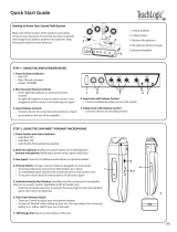
Before running wires to the FP 100 or plugging in, find a suitable, stable location
for the amplifier. Ideally, the teacher should have ready access and an electrical
outlet should be within six feet. The best possible location for the FP 100 is in a
media cabinet with any existing audio/video equipment.
Media Cabinet Set-up
SECTION 2:
SET-UP & USE
1. LOCATION OF THE AMPLIFIER
Avoid Separated Set-ups
Components should be housed
together. Wires should be routed
back directly to the amplifier.

11
1. Overview 2. Setup & Use
3. Optional
Accessories
4. Troublshooting
5. Warranty, Safety
& Specifications
2. IR SENSOR INSTALLATION
Good placement
Conduit is Recommended
Best placement
Avoid!
Sensor location is very important for optimum performance of the 820iR
Classroom Audio System.
• BEST: On the ceiling at or near the middle of the classroom.
• GOOD: High and centered on the long wall.
• AVOID: Locations in corners, on walls at heights lower than 7 feet, or in places
where the line of sight is or could be obstructed.

12
1. Overview 2. Setup & Use
3. Optional
Accessories
4. Troubleshooting
5. Warranty, Safety
& Specifications
2. IR SENSOR INSTALLATION CONT’D
1. Lift the ceiling tile nearest the grid rail in
your desired sensor location. Guide one
side of the C-clip over one edge of the
grid rail. Providing firm support to the
back of the grid rail with one hand (to
prevent bending), firmly and carefully
snap the second side of the C-clip over
the edge of the rail.
2. Uncoil sensor wire. Connect one
end of the sensor cable to the plug on
the sensor. Secure wire overhead and
route it back to
the system.
3. Connect the other end of the sensor
cable into one of the sensor inputs on
the back of the system.
1. Screw the plastic mounting strip to a place
high on the wall or in the middle of the
solid ceiling. Mount the strip horizontally
as shown above.
2. Firmly snap the C-clip on the back of the
IR sensor onto the plastic mounting strip
with the sensor plug hanging down (if a
wall mount) or toward the receiver location
(if ceiling mount).
3. Uncoil the sensor wire. Screw one end
of the sensor cable to the plug on the
sensor. Route the wire back to the system,
securing it along
the way.
4. Connect the other end of the sensor cable
to one of the sensor inputs on the back of
the system.
Suspended Ceiling Mount
Wall/Solid Ceiling Mount
sensor plug
c-clip
wall
mounting
strip

13
1. Overview 2. Setup & Use
3. Optional
Accessories
4. Troublshooting
5. Warranty, Safety
& Specifications
3A. CONNECTING TO THE AMPLIFIER
1. Locate the audio patch cable
2. Strip the cable’s rubber insulation
½” (see A in illustration) and then
strip the outer sheath of the signal
wire leaving ¼” exposed (see B in
illustration).
Audio
Patch
Cable
A
B
Ground
Wire
Signal
Wire
Outer
Sheath

14
1. Overview 2. Setup & Use
3. Optional
Accessories
4. Troubleshooting
5. Warranty, Safety
& Specifications
3A. CONNECTING TO THE AMPLIFIER CONT’D
3. Insert the stripped wires into the
marked openings, left and right, in
the Euro-block.
4. Secure the inserted wires by
tightening the retaining screws.

15
1. Overview 2. Setup & Use
3. Optional
Accessories
4. Troublshooting
5. Warranty, Safety
& Specifications
3A. CONNECTING TO THE AMPLIFIER CONT’D
5. Ensure the B/MIX switch is pushed
to the right to select the MIXED
output.
6. Connect the ¼˝ connector into the
audio or microphone input on the
existing amplifier.
This method allows for individual
control of each microphone channel
from the amplifier being used.
a. Obtain a second balanced audio
cable.
b. Strip the wire to reveal the
positive, negative, and grounded
conductors.
c. Fasten the wire to the available
CH A euro-block connector using
a small screw driver (observe the
proper polarity).
3B. INDIVIDUAL CHANNEL CONNECTION
(ALTERNATE CONNECTION METHOD)

16
1. Overview 2. Setup & Use
3. Optional
Accessories
4. Troubleshooting
5. Warranty, Safety
& Specifications
3C. FINALIZING CONNECTIONS
1. Ensure all top panel volume
controls are turned fully
counterclockwise.
2. Ensure audio output connection(s)
are securely connected into the FP
100 and the mixer/amplifier. Make
sure the CH.B/MIX switch is in the
appropriate setting based on your
output method (see pg. 14 for
more info).
3. Ensure sensor cable is attached
securely.
4. Ensure DC barrel end of the power
supply is connected to the DC
input on the FP 100.
5. Ensure AC adaptor end of the
power supply is connected to a
standard 110 VAC electrical wall
outlet.

17
1. Overview 2. Setup & Use
3. Optional
Accessories
4. Troublshooting
5. Warranty, Safety
& Specifications
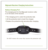
4. CHARGING THE REDMIKE VC
Before use, the REDMIKE VC should be charged. It will take 8-9 hours for the
REDMIKE VC to obtain a full charge. A fully charged REDMIKE VC will last for
over 7 hours of use. If microphones are used daily, they should be kept in the
cradle – microphones can be left in a charging cradle constantly for up to 2
weeks without causing degradation to battery life.
A red light on the charging cradle indicates the REDMIKE VC is charging.
A green light indicates that charging is complete and a full charge has
been reached. A blinking light indicates a charging or sensing error. See
Troublshooting section for more information.
REDMIKE VC incorporates alkaline protection into the microphone design.
Always use a Lightspeed rechargeable sensing battery. Replacement AA NiMH
batteries may only be purchased through Lightspeed Technologies (part # BA-
NH2A27). Do not attempt to charge alkaline batteries. They can overheat and
expand creating a significant hazard and damaging the microphone (this is not
covered by warranty).
1. Plug power cord into the cradle
charger and then plug the AC end
into an electrical outlet.
2. Ensure that the REDMIKE VC is
turned OFF.
3. Place the REDMIKE VC into the
cradle. The LED on the cradle
will glow RED indicating charging
has started. When the REDMIKE
VC is fully charged the LED on
the cradle charger will change to
GREEN.

18
1. Overview 2. Setup & Use
3. Optional
Accessories
4. Troubleshooting
5. Warranty, Safety
& Specifications
5. OPERATING THE REDMIKE VC
Once the REDMIKE VC is charged, follow these steps to set it up for use.
1. Turn the FP 100 power on. The
blue LED will glow.
2. Turn on the REDMIKE VC. The RED
IR LED on the FP 100 will light to
indicate a signal is being received.
3. Slip the REDMIKE VC with lanyard
around the neck and position the
top of the microphone just below
the collarbone. NOTE: Positioning
of the REDMIKE VC is critical for
proper volume adjustment.
4. While speaking in a normal voice,
increase the A VOLUME level until
your own voice is barely audible.
REMEMBER: this equipment is
designed to supplement and
distribute the teacher’s voice so he
or she is able to speak at a normal,
conversational tone. Having the
volume set too high will result in
feedback and listener fatigue.
Note: The REDMIKE VC has 9
volume levels. 4 up, 4 down and a
middle position. Be sure to start in
the middle position.
5. If a second REDMIKE VC was
purchased, repeat steps 2-4.
NOTE: Each REDMIKE VC has its
Channel pre-set to either A or B.
No further adjustment is necessary.
6. Once the normal level is set on the
FP 100, the user can now use the
REDMIKE VC volume controls to
adjust the microphone volume up
or down during normal classroom
operation.

19
1. Overview 2. Setup & Use
3. Optional
Accessories
4. Troublshooting
5. Warranty, Safety
& Specifications
USING THE REDMIKE VC TO AMPLIFY
EXTERNAL AUDIO EQUIPMENT
The REDMIKE VC includes a 3.5mm audio input jack to connect to an audio
source like a laptop or MP3 player. The REDMIKE VC will transmit the audio
signal to be played through the system.
If your system includes two REDMIKE VCs, use the student microphone
(already set to Channel B). NOTE: This feature works on both channels but we
recommend using Channel B so the teacher’s volume on the CH A does not have
to be adjusted.
The optional LT-71 can also amplify external audio. Simply plug the 3.5mm patch
cable from the audio source into the input labeled “AUX IN” and adjust the
volume of the source to the desired sound level.
1. Plug your external audio
equipment (for example, laptop),
into the input on the REDMIKE VC
labeled “INPUT” using a 3.5mm
patch cable.
2. Adjust the volume of the selected
mic channel to achieve desired
loudness.
AUDIO
OUTPUT
AUDIO
INPUT

20
1. Overview 2. Setup & Use
3. Optional
Accessories
4. Troubleshooting
5. Warranty, Safety
& Specifications
SECTION 3:
OPTIONAL ACCESSORIES
1. POWER BUTTON: Press this
button to turn the REDMIKE ON,
press again to turn it OFF (mute).
2. POWER/LOW BATTERY
INDICATOR: A BLUE light
indicates the REDMIKE is on and
fully charged. A RED light indicates
a charge is needed.
3. BATTERY COMPARTMENT: To
access the battery compartment,
slide the door downward. The
battery should only be replaced
by a Lightspeed AA rechargeable
sensing battery (part # BA-
NH2A27).
4. YELLOW PROTECTIVE TAB:
Slide the battery compartment
door open to remove this
disposable protective tab before
use. NOTE: do not attempt to
remove the tab without first
opening the compartment door, as
it may tear, leaving fragments.
5. AUDIO/MICROPHONE INPUT:
Use this input to plug in a laptop,
MP3 player or other audio
source to wirelessly transmit
audio to be played through the
system. Alternatively, an external
microphone can be connected.
6. CHANNEL SELECT SWITCH
(CH A/B): This switch allows
for selection between Channel
A or B. If you are using a single
microphone, we recommend using
Channel A.
7. CHARGER CONTACTS (+ -):
These contacts interface with the
charging tabs in the BC-RMCC
cradle charger for daily charging.
Simply place the REDMIKE in the
charger.
REDMIKE CONTROLS AND CONNECTIONS
S
l
i
d
e
b
a
t
t
e
r
y
d
o
o
r
o
p
e
n
R
e
m
o
v
e
t
a
b
b
e
f
o
r
e
u
s
e
7
1
2
3
5
6
4
/